📌 Key Takeaways
- •[M1] Sunon MF80201V1-1000U-A99 MagLev Motor Fan Specification for Approval — Sunonwealth Electric Machine Industry Co., Ltd. — https://www.elpro.org/gb/index.php?controller=attachment&id_attachment=24291 (Research A [S1])
- •[M2] Sunon GB0502AFB1-8 DC Brushless Fan & Blower Datasheet — Sunon — https://www.alldatasheet.net/html-pdf/1879398/SUNON/GB0502AFB1-8/551/3/GB0502AFB1-8.html (Research A [S2]; Research B [S2])
- •[M3] About Sunon — Sunonwealth Electric Machine Industry Co., Ltd. — https://www.sunon.com/en/about.aspx (Research A [S3])
- •[M4] Delta AFB0712/24 Series Ball Bearing Fan Specification — Delta Electronics — https://www.delta-fan.com/Download/Spec/AFB0724MC-F00.pdf (Research A [S4])
- •[M5] Fan Bearings & Longevity — DigiKey TechForum — https://forum.digikey.com/t/fan-bearings-longevity/13294 (Research A [S5])
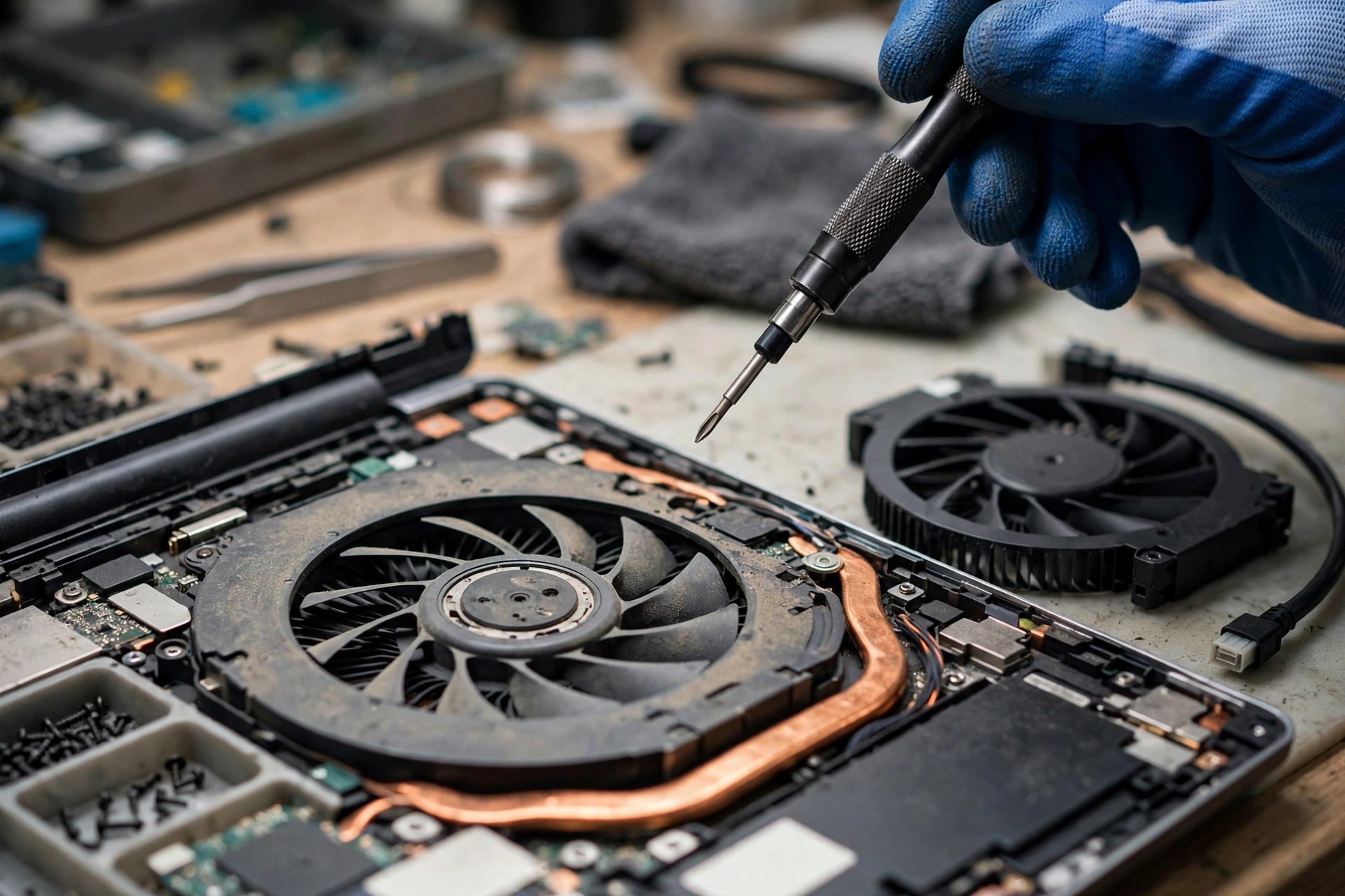
When a user says "my fan is broken," the repair bench can be looking at more than a dozen completely different things: a fan that does not spin at all, a fan that spins for a while and then stops, a fan error at boot, a fan that keeps getting louder, a fan that is quiet at low speed but shakes the whole machine at full speed, a machine that will not cool down even though the fan is clearly spinning, or a speed reading of zero while the fan can plainly be heard. Behind those symptoms the hardware can differ by a whole module — from the coils and magnets that produce torque, to the bearing that supports the shaft, to the blades that move the air, to the housing that fixes and ducts the fan, to the cable that supplies power and reports speed. Any one of those layers can fail, and every one of them presents itself as "a broken fan." This article takes the fan module apart into five layers — motor, bearing, blades, housing, and cable — and explains, layer by layer, the materials, the failure mechanisms and the inspection direction, then narrows the fault down with a damage conduction chain, layered symptom elimination, a bearing-type comparison, a noise classification, brand differences, the Hong Kong context, eighteen misdiagnosis traps, and a repair decision framework.
This is an advanced, mechanism-level article focused on the physical failure of the fan module itself. It divides the work with the articles already on this site: loud-fan-noise covers the general causes of noise, fan-not-spinning-thermal-shutdown covers the consequences of a fan that does not spin and the resulting thermal shutdown, fan-pwm-controller-driver-failure-advanced-hk covers the embedded controller and PWM controller layer, fan-motor-bearing-failure covers general motor and bearing failure, and heatsink-heatpipe-thermal-module-failure covers the thermal module. The distinctive contribution of this article is the five-layer dissection, the damage conduction chain, the four-bearing comparison, the evolution of the noise spectrum, and the mechanism-level analysis of cable fretting corrosion [B-S15][A-S18]. Teardown, measurement, swap testing and soldering are all jobs for professional inspection; this article does not teach do-it-yourself teardown and does not provide step-by-step repair instructions. The price of a fan itself is always subject to a written quote after inspection.
Chapter 1: The fan module is not one motor, it is five layers
The great majority of laptop fans are centrifugal blowers, not the axial fans common in desktop machines: air is drawn in from the side and discharged through the outlet, which suits a thin chassis [B-S48]. The geometric relationship between the blades, the housing and the outlet is therefore more sensitive than in an axial fan: a small change in the clearance between the blade tips and the housing changes airflow and noise at once. The fan module is also a three-in-one component — mechanical, electrical and aerodynamic. The bearing and the blades belong to the mechanical layer, the motor coils and the driver IC belong to the electrical layer, and the blade shape and the housing duct belong to the aerodynamic layer. A problem in any one of the three leaves traces in the other two, so looking at only one layer invites misdiagnosis [B-S38][B-S39].
Dell service manuals list the fan as a separately removable part and describe the fan cable and the motherboard connector separately, which shows that the fan is a modular component in its own right [A-S16][A-S17]. Lenovo hardware maintenance manuals list the "Thermal fan assembly" as a field-replaceable unit and require the connector to be firmly seated on installation, without pressing on the fan cover or the fan hub [A-S20][A-S21]. HP service guides list the fan and the heatsink as a "Fan / heat sink assembly" and note that thermal material must be handled together when replacing it, which shows that in some models the fan and the thermal module are supplied bound together [A-S22][A-S23]. ASUS service manuals list the "Thermal & Fan Module" as one module and give separate removal notes for the fan and the thermal module, which shows that the two can be inspected separately even though the supply form varies by model [A-S24][A-S25].
| Layer | Core parts | Main function | Typical failure modes | Replacement scope (principle) |
|---|---|---|---|---|
| Motor layer | Coils, magnets, Hall sensor, driver IC | Produces rotational torque | Coil short circuit or open circuit, Hall sensor failure, driver IC failure, magnet demagnetisation | Normally the whole fan module must be replaced |
| Bearing layer | Sleeve, ball, magnetic levitation and fluid bearings | Supports the shaft, low-friction rotation | Lubricant drying out, clearance growing, pitting, magnetic force decaying | Normally the whole fan module must be replaced |
| Blade layer | Blades, hub | Moves air | Blade breakage, chipping, deformation, hub cracking, dynamic imbalance | Normally the whole fan module must be replaced |
| Housing layer | Frame, fixing feet, air duct | Fixes, ducts and protects | Cracking, deformation, broken fixing feet, blocked duct | Depends on the extent of damage: the fan alone, or the thermal module as well |
| Cable layer | 4-pin cable, connector, PWM control wire | Power, speed reporting, speed control | Oxidation, breakage, poor contact, loose pins | The cable or connector alone, or the whole fan module |
The geometric sensitivity of a blower is worth examining one level deeper. In an axial fan the air moves straight along the axis, in and out, so a change in the clearance between the blades and the frame affects airflow relatively gently. In a blower the air is drawn in from the side, turned through ninety degrees, and then discharged through the outlet, so the clearance between the blade tips and the volute directly decides whether air leaks back to the intake side through the gap. If the clearance grows even slightly, leakage increases at once and the fan has to run faster to maintain the same airflow; if the clearance shrinks even slightly, the blades can scrape the volute. A Sunon specification lists the material of both the fan frame and the blades as UL 94V-0 thermoplastic PBT, together with a working temperature range of minus 10 to 70 degrees Celsius [B-S5]. Writing the material and the temperature range down together means that outside that range, the dimensional stability of the frame is no longer guaranteed by the specification, and the risk of deformation has to be assessed separately. A Nidec fan specification likewise lists the housing material as PBT [A-S14]. The advantage of PBT is stiffness and heat resistance; its disadvantage is that it is relatively brittle under impact, and once a crack appears it tends to spread along the thin wall. That material character explains why housing cracks so often start at one impact point and only later spread into vibration and noise.
Another concept worth clarifying is the difference between a module and a part. Dell manuals list the fan as a separately removable part, Lenovo manuals list it as a field-replaceable unit, and HP manuals list the fan and the heatsink of some models as one spare part unit. All three wordings describe the supply and replacement unit, not the physical structure. Physically, a fan is always made of five layers; in supply terms, which layers are sold together depends on the parts list of that model. Mistaking the supply unit for the physical structure is a common starting point for misdiagnosis: assuming the fan and the heatsink are one piece leads to skipping the cable check, while assuming the fan is an independent part leads to skipping the check of the joint between the fan and the heatsink fins. The correct questions are always two: which layer is physically broken, and which pieces must be replaced together in supply terms.
Chapter 2: The motor layer — coils, magnets, Hall sensor, driver IC
A laptop fan motor is a brushless DC motor, using electronic commutation instead of carbon-brush commutation [A-S10]. Microchip's application note explains that the stator windings of a brushless DC motor must be energised in sequence for the motor to rotate, and that the rotor position is detected by Hall-effect sensors embedded in the stator [A-S10]. A Sunon specification lists one of its fans as a single-phase, four-pole brushless DC motor [B-S5]; a Delta specification likewise lists a fan motor as two-phase, four-pole [B-S12]. Unlike a brushed motor, a brushless motor has no carbon brushes and no commutator; commutation is done by an electronic circuit, so there is no brush wear, but whether commutation is correct depends entirely on position detection [B-S34].
The motor layer has four sub-components, and the failure of any one of them can leave the fan not spinning, spinning unsteadily, or stopping intermittently. The coil is wound from enamelled wire; ageing or damage to the insulation causes inter-turn short circuits, while a break in the wire causes an open circuit [A-S32][A-S33]. The magnets are normally permanent magnets; the magnetic field of the magnets interacts with the magnetic field of the stator coils to produce torque, so a fall in magnetic force directly weakens torque [A-S38][A-S39]. The Hall sensor reports the rotor position to the driver IC; damage to the sensor, poor contact or a shift in position all deprive the controller of position feedback [A-S32]. The driver IC sits on a small circuit board inside the fan module and handles commutation, PWM interpretation and protection. The Texas Instruments DRV10983 datasheet states that the driver integrates power MOSFETs, can deliver a continuous 2 A drive current, and achieves sinusoidal commutation using a back-EMF scheme [A-S11].
| Motor-layer failure | Mechanism | Typical symptoms | Layer easily confused with it |
|---|---|---|---|
| Inter-turn coil short circuit | Enamel damaged, adjacent turns touch, current concentrates, local overheating [A-S32][A-S33] | Speed cannot reach the rated value, current rises, fan runs at high speed for long periods, temperature will not fall | Aged thermal paste, rising bearing resistance |
| Coil open circuit | Winding wire broken or a joint detached, one phase cannot be energised [A-S32][A-S33] | Does not spin at all, or shudders when starting and repeatedly tries to start and stops | Interrupted cable power, driver IC failure |
| Hall sensor failure | Sensor ageing, magnet demagnetisation or position shift, commutation signal distorted [A-S9][A-S32] | Speed drifts, difficult starting, repeated retrying | Burnt-out motor, embedded controller failure |
| Magnet demagnetisation | Prolonged high temperature reduces the flux of the permanent magnet, so the same current produces less torque [A-S38][A-S39] | Spins but stays at a persistently low speed, stalls when the load rises slightly | Coil short circuit, late-stage bearing wear |
| Driver IC failure | Commutation, PWM interpretation or protection circuit failure [A-S11] | Does not spin, stops intermittently, speed jumps | Motherboard embedded controller, poor cable contact |
The difference between the Hall-sensing scheme and the sensorless back-EMF scheme is worth examining one level deeper, because the two schemes fail in completely different ways, and taking the wrong direction in diagnosis wastes the whole inspection. The Hall scheme measures magnetic polarity directly with a physical sensor. Its advantage is that the rotor position is known even at start-up, so low-speed commutation is accurate; its disadvantage is one more physical component that can age, absorb moisture and shift, and a small change in the air gap between the sensor and the magnet distorts the signal at once [A-S9]. The back-EMF scheme estimates rotor position by measuring the induced voltage in the unenergised phase. Its advantage is that there is no sensor, so the structure is simpler; its disadvantage is that there is no back-EMF at all when the rotor is stationary, so starting must rely on open-loop dragging to establish a signal, and low-speed commutation is less stable [A-S11]. The Texas Instruments DRV10983 datasheet states that the driver achieves sinusoidal commutation with a back-EMF scheme and integrates power MOSFETs [A-S11]; Microchip's commutation logic document also explains that the commutation sequence of a brushless DC motor must correspond strictly to the rotor position [A-S49]. The first question in diagnosis should be: which scheme does this model use? Get that wrong, and every measurement direction that follows will be wrong. If a Hall-scheme fan has difficulty starting, the sensor should be suspected; if a back-EMF fan has difficulty starting, the starting drag and the current limiting should be suspected. The handling of the two is different and cannot be interchanged.
The protection functions of the driver IC itself are also worth knowing, because a protection action can impersonate a fault. The controller in patent application US 2006/0208675 has an internal fault timer with automatic restart, a motor start timer, programmable cycle-by-cycle current limiting, power undervoltage lockout and overtemperature protection [B-S36]; the locked-rotor protection unit of US patent 6,023,139 uses Hall signal edge detection to judge whether the fan is locked, generates a locked signal to switch off the driver, and issues a restart signal to try restarting the locked fan [B-S35]. The purpose of these protections is to prevent burning out, but from the user's point of view a protection action looks almost identical to a fault: the fan spins for a while and stops, tries again after a pause, or its speed suddenly jumps. The way to tell a protection action from a genuine fault is not to look at one moment, but to look at the pattern: a protection action has a regular retry interval, and the rotor shudders slightly on each retry, while a genuine fault is mostly irregular or shows no response at all. That distinction is a mechanism inference and must finally be confirmed by professional measurement. If a coil short circuit spreads, the driver IC may enter a protection state because of overcurrent, so the fan stops intermittently; at that point the symptoms resemble poor cable contact, and the layers must be eliminated one by one rather than deciding directly which layer it is.
Chapter 3: The bearing layer — from a thinning oil film to seizure
A bearing depends on a thin film of lubricating oil separating the metal surfaces, reducing energy loss and overheating [A-S29]. Bearing failure does not happen overnight; it follows a course that can be described in stages: lubrication decay, clearance growth, and structural damage. In the first stage, lubrication decay, the oil film thins and the metal surfaces begin to touch microscopically; the noise gains a low-frequency hum on top of the original airflow sound, while speed shows no obvious fall because the motor can still compensate. In the second stage, clearance growth, shaft wobble makes the blade-tip clearance uneven, intermittent scraping appears, the noise spectrum spreads from low frequency towards high frequency, and speed becomes unsteady as the load changes. In the third stage, structural damage, ball pitting or scoring of the sleeve bore produces regular knocking, speed falls markedly, or starting fails and motor current rises.
| Stage | State inside the bearing | Observable features | Speed and airflow |
|---|---|---|---|
| Stage 1: lubrication decay | Oil film thins, metal begins microscopic contact [A-S6][A-S29] | Low-frequency hum, more obvious when cold or starting | Speed close to normal, airflow not necessarily obviously reduced |
| Stage 2: clearance growth | Shaft wobbles, blade-tip clearance becomes uneven [B-S2] | Intermittent scraping, high-frequency squealing, vibration growing | Speed drifts with load, airflow becomes unsteady |
| Stage 3: structural damage | Ball pitting, sleeve bore scored [A-S29][A-S31] | Regular knocking, failed starting, speed falling markedly | Speed falls or the fan stops, airflow collapses |
One failure mode of ball bearings is fatigue of the raceway surface: repeated rolling contact causes the surface material to flake off, forming pits [A-S29][A-S31]. Kaydon's bearing corrosion white paper states that corrosion is the natural enemy of rolling bearings; damage from moisture, vapour and acidic substances attacking the bearing surface often only becomes obvious at a late stage [A-S30]. The audible character of pitting is generally a regular clicking or metal friction sound whose frequency rises with speed, but the audible character is only a reference, and final location must be confirmed by professional inspection. A magnetic levitation bearing supports the rotor with magnetic force and reduces mechanical contact. Sunon notes that the magnetic levitation design lets the rotor float while rotating, so the shaft and the bearing do not touch directly [A-S2]. In practice, bearing problems in a magnetic levitation fan are harder to judge from appearance; if a fan shows speed-related vibration while the blades and the housing show no visible damage, the bearing layer is one of the directions to consider. The speed of the progression varies with the environment; high temperature, high humidity and dust all accelerate lubricant degradation and corrosion.
Why the failure curve of a sleeve bearing is so steep is worth examining one level deeper. Sunon technical documents state that the oil ring and pads of a conventional sleeve bearing increase the friction area and hinder heat dissipation, while the magnetic levitation structure no longer uses an oil ring or pads [B-S2]. That explains why the failure curve of a sleeve bearing is steeper: once lubrication is lost, friction and heating amplify each other. At first, as the oil film thins, friction rises only slightly, and the motor compensates with a slightly higher current, so the speed looks normal on the surface. The heat produced by friction makes the lubricating oil oxidise faster, become thinner and run out more easily, so the film thins further and friction rises again. That positive feedback means a sleeve bearing can travel from a slight noise to seizure in a short time, especially in a machine that runs hot for long periods. The failure curve of a ball bearing is relatively gentler, because the balls and the raceways roll rather than slide, so even after lubrication fails there is still metal rolling support for a while. The weakness of a ball bearing is that once pitting appears, rolling becomes jumping: every ball produces one impact as it passes over a pit, and the impact enlarges the pit. The two bearing types have different failure curves and therefore different repair time limits. When a sleeve bearing makes its first noise, that is already a signal to send the machine for inspection soon; when a ball bearing starts squealing at high frequency, the progression is slower, but once pitting has formed it will not heal by itself.
The structure of a magnetic levitation bearing is also worth explaining clearly, because magnetic levitation is often misunderstood as meaning no wear and no failure. Sunon's MagLev design uses magnetic force to float the rotor, reducing the friction produced by direct contact between the shaft and the bearing. Sunon states that the company developed the world's first magnetic levitation motor fan [A-S2][A-S3][B-S48]. Magnetic levitation reduces the mechanical contact between the shaft and the bearing; it does not eliminate all wear. The magnetic assembly itself is affected by high temperature, the sealing structure ages, and once the rotor wobbles, the geometry of the magnetic support changes at once. Failure of a magnetic levitation bearing is less common, and when it appears it is mostly damage to the magnetic assembly or the sealing structure, with sudden wobble rather than gradual wear. That judgement is an inference and must be verified case by case. On fluid bearings, Nidec states that the fluid dynamic bearing was originally designed to replace ball bearings in hard disk spindle motors to reduce vibration, and was later used in thin laptop fans [B-S6]. The bearing surface is engraved with herringbone and circulation grooves, which generate dynamic oil pressure at high speed and form an oil film that supports the shaft [B-S8]. The oil film can only be established by speed, so at the instant of starting, before the film is established, noise and wear risk are highest. That explains why the starting noise of a fluid bearing fan is worth attention, rather than being treated as normal in every case.
Chapter 4: The blade layer — chipping, cracking and dynamic balance
The blades consist of several vanes and a central hub. The shape and the angle of the vanes determine airflow and static pressure, and the hub connects the shaft to the motor rotor [A-S15]. The vanes are thin-walled plastic parts with limited impact resistance; a drop, squeezing or a foreign object drawn in can break or deform a vane. The causes of blade breakage include foreign objects drawn in, drop impacts, fatigue cracks from prolonged vibration, and improper force during removal and refitting. A damaged blade does not necessarily stop the fan at once; the fan may keep turning, but vibration and noise grow as speed rises and airflow falls.
A hub crack is less often visible to the naked eye, but a crack changes the stiffness of the hub and lets the blades deform asymmetrically at high speed. If a hub crack keeps spreading, a blade can detach and jam the fan, causing a sudden stop and a risk of overheating. Dynamic imbalance means the centre of mass of the rotor is offset from the axis of rotation, so rotation produces a centrifugal force whose direction keeps changing [A-S35][A-S36]. Vibromera notes that even a slight imbalance in a fan rotor produces obvious vibration, and that the causes of imbalance include blade wear, uneven dust, loose assembly and blade deformation [A-S35].
Centrifugal force is proportional to the unbalanced mass and to the square of the rotational speed: the higher the speed, the greater the force produced by the same imbalance. This explains why a chipped fan vibrates only slightly at low speed but violently at full speed. The international standard ISO 21940-11 defines balance quality grades for rigid rotors and provides a formula for converting a grade into the permissible residual imbalance; fans generally fall within the G6.3 grade range [A-S36][A-S37]. A chipped blade is therefore not a small problem: it is a noise source, a vibration source and a cause of accelerated bearing wear at the same time. The correct handling is to replace the whole fan module rather than try to repair a blade, because a repaired blade can hardly recover the factory dynamic balance. A Nidec fan specification lists the housing material as PBT and the bearing as a ball bearing [A-S14]; a Sunon specification lists both the fan frame and the blades as UL 94V-0 thermoplastic PBT [B-S5]. The material itself sets the brittleness boundary of the blades: thin-walled plastic has little margin against impact and fatigue.
| Blade damage form | Cause | How the symptoms evolve | knock-on effect |
|---|---|---|---|
| Chipped blade | Foreign object drawn in, drop impact [A-S15] | Slight vibration at low speed, violent vibration at full speed | Dynamic imbalance, accelerated bearing wear [A-S35] |
| Deformed blade | Prolonged high temperature, squeezing, improper force during removal | Airflow falls, wind-cutting noise becomes coarse, noise rises with speed | Aerodynamic efficiency falls, motor load rises |
| Cracked blade | Fatigue crack, micro-crack spreading after impact | Silent or slightly noisy at first, then sudden breakage | Blade detaches and jams the fan, sudden stop |
| Hub crack | Impact, prolonged vibration, material fatigue | Asymmetric deformation at high speed, intermittent noise | Risk of blade detachment, rotor wobble worsens |
| Uneven dust build-up | Dust plus moisture caking, accumulating on one side [B-S39] | Gradual rise in vibration and noise | Acquired imbalance, rising cyclic load on the bearing |
Chapter 5: The housing layer — cracks, deformation and broken fixing feet
The housing has three jobs: fixing the fan in the chassis, defining the air duct, and protecting the rotor and the blades. Deformation of the housing changes the clearance between the blades and the frame; a clearance that is too small lets the blades scrape the frame, while a clearance that is too large lets airflow fall. In a blower, the clearance between the blade tips and the housing is extremely narrow, and it sets aerodynamic efficiency and noise. If the housing is hit or deformed by prolonged heat, the clearance narrows locally and each revolution of the blades produces one scrape, giving a regular knocking sound; if the clearance widens locally, air leaks through the gap, airflow falls, and the fan has to run faster to compensate [B-S48].
The ASUS service guide warns that the correct technique must be used when removing and refitting a fan, so that the fan is not deformed [A-S24][A-S26]; the Lenovo maintenance manual likewise warns that rough handling of a fan can cause deformation and poor contact [A-S19]. The diagnostic clue for housing deformation is that it depends on angle: the symptoms change with the tilt of the chassis, because gravity changes the direction of rotor wobble and the scraping appears only at a certain angle. Housing deformation can also shift the mounting position of the fan, so that a gap opens where the duct meets the heatsink fins and hot air flows back.
A fan with a broken fixing foot will vibrate even if the motor and the bearing are normal, because the mounting is unstable. Replacing the fan module is the more direct handling; trying to fix it with glue is unreliable, because the durability of a glued fix has not been verified by the manufacturer. A blocked duct raises air resistance, so the fan has to run at a higher speed to maintain airflow, and the load on the bearing and the motor rises. Cleaning can only clear the blockage; it cannot repair a deformed housing, so if the housing is already deformed, vibration and noise may remain after cleaning. Dell support documents list physical damage to the fan or the air outlet and a blocked air outlet side by side as common causes of fan faults and overheating [A-S18][B-S15].
| Housing damage form | Cause | Symptoms | Handling principle |
|---|---|---|---|
| Frame crack | Drop impact, prolonged vibration, force during removal [A-S24] | Intermittent knocking, vibration, falling airflow | Depends on the location and extent of the crack: replace the fan alone or together with the thermal module |
| Frame deformation | Impact, prolonged high temperature, pressure during installation | Blade scraping, angle-dependent noise, falling airflow | Cleaning cannot repair deformation; the module must be replaced |
| Broken fixing foot | Impact, over-tightened screw, material fatigue | The whole machine vibrates even though the motor is normal | Replace the fan module; a glued fix is unreliable |
| Blocked duct | Dust, hair and debris accumulating [B-S15] | Fan runs at high speed for long periods, temperature will not fall, weak outlet airflow | Cleaning can improve it, but the bearing must also be checked for wear |
| Duct joint gap | Housing deformation, mounting shift | Hot air flowing back, temperature rising repeatedly | Professional inspection must confirm the state of the joint |
Chapter 6: The cable layer — physical failure of the 4-pin PWM cable
A laptop fan commonly uses a four-wire interface. The Intel four-wire PWM specification defines pin 1 as ground, pin 2 as plus 12 volts, pin 3 as speed reporting, and pin 4 as PWM control [A-S12]. Noctua technical documents state that the four wires of a four-pin fan are ground, power, speed feedback and PWM control; the PWM target frequency is 25 kHz, with an acceptable range of 21 to 28 kHz; and the speed feedback signal is an open-collector output of two pulses per revolution [B-S13]. A three-pin fan has only ground, power and speed feedback, with no independent PWM control wire, so speed must be adjusted by changing the supply voltage [B-S14]. A Delta specification gives the speed feedback waveform: for a four-pole fan, speed is calculated from TS, and RPM equals 60 divided by TS [B-S9].
In a laptop, the cable is normally a fine wire harness with a miniature socket rather than the standard four-pin plug of a desktop machine, but the signal logic is the same: power, PWM and speed feedback are all indispensable. If the speed feedback wire breaks, the system receives no speed signal and may wrongly judge that the fan has stopped and report an error or force full speed. If the PWM wire breaks, the fan may lock at full speed or at minimum speed, depending on the default behaviour of the driver IC. If the power wire makes poor contact, the fan loses speed intermittently. Dell manuals state that the fan cable connects to the FAN1 or FN1 socket on the motherboard [A-S16][A-S17]; Lenovo manuals require the connector to be firmly seated on installation [A-S20].
| Pin | Signal | Consequence of a break or poor contact |
|---|---|---|
| Pin 1: ground | Ground return [A-S12] | Unstable power, drifting speed, intermittent stopping |
| Pin 2: power | Power supply [A-S12] | Fan loses speed, fails to start, spins on and off |
| Pin 3: speed reporting | Two pulses per revolution [B-S13] | System reads 0 RPM while the fan is turning, wrongly reports a fan error, forces full speed |
| Pin 4: PWM control | Duty-cycle control at 25 kHz [B-S13] | Fan locks at full speed or minimum speed, speed no longer follows temperature |
When speed reporting is abnormal, the embedded controller may wrongly judge a fan fault and trigger protection, for example by raising the speed, issuing a warning or shutting down; in that case the root cause is in the cable, not in the fan motor itself. The embedded controller and PWM controller sit on the motherboard and issue PWM commands based on temperature sensor readings, while monitoring the speed feedback [A-S12]. Confusing a cable problem with a controller problem is one of the most common misdiagnoses. The gold fingers wear a little more with every insertion and removal, and once the gold plating is worn through, the underlying metal oxidises faster. If the tolerances of an aftermarket fan plug do not match the original socket, contact pressure after mating is insufficient and commuting vibration gradually loosens it. Wear or loosening mostly appears after a repair or a fan replacement, while oxidation mostly appears in older machines that have not been opened for a long time; both require professional inspection to measure contact resistance and the mated state, and neither can be judged from appearance alone.
| Intermittent pattern | More likely pointing to | Distinguishing point |
|---|---|---|
| Speed suddenly jumps, the system reports a fan error and then recovers by itself | Poor contact on the speed feedback wire [B-S13] | The speed reading jumps in steps rather than changing gradually |
| Fan suddenly runs at full speed, noise rising in a step | PWM wire broken or in poor contact, driver IC defaulting to full speed | Sudden full speed unrelated to temperature |
| Fan suddenly stops, resumes when the chassis is tapped lightly | Poor contact on the power wire or a loose socket | Stopping related to vibration or angle |
| Symptoms only in humid weather or when moving between an air-conditioned room and outdoors | Connector oxidation, condensation [B-S42][B-S43] | Related to humidity and temperature difference, not to speed |
Chapter 7: The damage conduction chain — how the five layers drag each other down
The core model of this article is a damage conduction chain, not five isolated faults. A typical chain runs as follows: bearing lubrication is lost or the bearing wears, so the radial clearance of the shaft grows and the rotor begins to wobble; the blade-tip clearance becomes uneven and the blades scrape the housing intermittently; the blade edges wear or chip and dynamic balance is further damaged; vibration is amplified in proportion to the square of speed and the bearing takes an extra cyclic load; the motor raises its current to maintain speed and the coil temperature rises; coil insulation degrades faster and the risk of inter-turn short circuits rises; torque falls, speed drifts or the rotor locks, and the driver IC triggers locked-rotor protection; airflow collapses and the processor throttles or the machine shuts down from overheating. The key to this chain is positive feedback: every step makes the next step easier.
Sunon's MagLev technical documents are written precisely against the head of this chain: in a conventional motor the whole weight of the rotor presses on the shaft, and friction between the shaft and the inner wall of the bearing bore makes the wall rough and uneven, whereas the magnetic levitation design supports the rotor with magnetic force so that the shaft and the bearing do not touch directly while rotating, reducing friction [A-S2][B-S2]. In other words, the bearing is the head of the chain, and protecting the bearing slows the whole chain down. Another common chain runs from the outside in: the housing is deformed by an impact, the blade-tip clearance narrows locally, the blades scrape the housing, a blade chips, dynamic balance is damaged, the bearing wears faster, and the chain returns to the main path [A-S19][B-S26]. The ASUS service guide warns that the correct technique must be used when removing and refitting a fan, so that the fan is not deformed [A-S26][B-S26]; the Lenovo maintenance manual likewise warns that rough handling of a fan can cause deformation and poor contact [A-S19]. The geometric precision of the housing and the blades is the starting point of this chain.
A third chain starts in the electrical layer: poor cable contact interrupts the power or PWM signal intermittently, the motor restarts repeatedly and its speed drifts; every restart sends a starting-current surge through the coil and the driver IC, causing local overheating and insulation degradation [B-S34][B-S35]. This chain is the easiest to misjudge as an embedded controller fault or a motherboard problem. A fourth chain starts in the aerodynamic layer: a duct caked with dust raises the static pressure demand, the fan runs at high speed for long periods to compensate, the bearing and the motor stay under high load, the lubricant degrades faster, and the chain returns to the main path. Dell support documents list physical damage to the fan or the air outlet and a blocked air outlet side by side as common causes of fan faults and overheating [A-S18].
| Conduction chain | Starting point | Sequence | End point |
|---|---|---|---|
| Main chain: bearing first | Bearing lubrication lost [A-S29] | Wobble, scraping, chipping, imbalance, current rising, insulation degrading | Locked-rotor protection, airflow collapse, thermal shutdown |
| Outside-in chain: housing first | Housing deformed by impact [B-S26] | Clearance narrowing, scraping, chipping, imbalance, bearing wear | Returns to the middle of the main chain |
| Electrical chain: cable first | Poor cable contact [A-S43] | Power or PWM interrupted intermittently, repeated restarts, starting-current surges | Coil insulation degrading, driver IC damaged |
| Aerodynamic chain: duct first | Duct caked and blocked [B-S15] | Static pressure demand rising, prolonged high speed, bearing under high load | Lubricant degrading faster, returns to the main chain |
Chapter 8: The physics of speed, airflow, static pressure and noise
A fan specification describes one fan with four numbers: speed, airflow, static pressure and noise [B-S5][B-S9][B-S12]. The relationship between the four is a trade-off, not a free lunch: when speed rises, airflow and static pressure rise, but noise rises faster. The Delta AFB0812VHB specification lists 3,700 RPM with airflow of about 39.2 CFM, static pressure of about 4.77 mmH2O and noise of about 39.5 dB(A) [B-S12]; higher-speed models in the same series show noise figures rising in step. Static pressure is the ability of a fan to overcome duct resistance. A laptop duct is narrow and its fins are dense, so if static pressure is insufficient, the actual airflow through the fins stays low even when the nominal airflow is high; that is why laptops use blowers rather than large-diameter, low-static-pressure axial fans [B-S48].
A noise figure is an average, and it cannot be compared when the measurement conditions differ. Sunon specifications state that noise is an average value [B-S5]; Delta specifications likewise mark noise as an average value [B-S9]. When an article quotes a decibel figure it must also state the speed and the measurement conditions, or the figure is meaningless. The decibel is a logarithmic unit: a difference of 3 dB is roughly a doubling of sound power, but what the human ear perceives depends on the spectrum. A high-frequency squeal can feel piercing even when its decibel figure is not high, and a low-frequency hum can be mistaken for normal fan sound even when its decibel figure is higher. Inspection should therefore not only ask how many decibels, but how the spectrum changes, how it changes with speed, and how it changes with angle and temperature. Those three changes are the diagnostic information at the mechanism level.
| Parameter | When speed rises | How it changes when the fan fails |
|---|---|---|
| Speed, RPM | Rises | In late bearing wear it cannot reach the rated value, with Hall failure it drifts, with a locked rotor it is zero |
| Airflow, CFM | Rises | Falls when blades deform or chip, leaks when the housing clearance widens, falls when the duct is blocked |
| Static pressure, mmH2O | Rises | Demand rises when the duct is blocked, supply falls when the blades deform |
| Noise, dB(A) | Rises faster | Bearing wear moves the spectrum from low frequency to high frequency, scraping adds knocking |
Why measurement conditions matter so much is worth examining one level deeper. The noise figure in a fan specification is generally expressed in dB(A), where the A-weighting simulates the sensitivity of the human ear to different frequencies, but the measurement distance, the measurement environment, the background noise, the speed and the supply voltage all affect the figure. Sunon specifications state that noise is an average value [B-S5], and Delta specifications likewise mark noise as an average value [B-S9]. The words average value mean that the figure has already averaged out momentary peaks, so it cannot be compared directly with the peak value of another fan. Even when two fans show the same noise figure, their spectra can be completely different: one may be a low-frequency hum and the other a high-frequency squeal, and what the human ear feels is completely different as well. Comparing decibels with a phone recording at a repair bench is even less reliable: a phone microphone responds differently to different frequencies, and a difference of a few centimetres in recording distance already changes the figure by several decibels. The correct way to compare is not to compare figures, but to compare changes: on the same machine, in the same position and at the same speed, how does the noise spectrum change; and how does the spectrum change before and after the noise appears. Those two changes are the diagnostic information; a single figure is not. Vibration analysis literature states that the typical character of imbalance is a strong peak at one times the rotational speed, that bearing defects show characteristic patterns at defect frequencies, sidebands and higher-frequency energy bands, and that the typical character of looseness is multiple rotational-speed harmonics [B-S38]. Those spectral characters cannot be seen from a decibel figure alone.
Chapter 9: Noise classification — six sounds, each pointing to a different layer
Noise is the richest diagnostic information in a physical fan failure, but only if the kind of sound is distinguished, rather than describing everything vaguely as loud. The six kinds of noise below each have a different physical source, a different spectral character and a different corresponding layer. One machine can move from one kind to another at different stages, and the change itself is evidence of the progression.
| Noise | What it sounds like | Most likely physical failure | Note |
|---|---|---|---|
| Humming (low frequency, rising and falling with speed) | A continuous low drone, like a distant motor | Early bearing wear, slight rotor wobble, slight dynamic imbalance | Dominant frequency at one times speed [B-S38] |
| Squealing (high frequency, sharp) | Like metal friction or cicadas, more obvious at high speed | Ball pitting, dry grinding of the sleeve, lubricant exhausted | High-frequency energy band rising [B-S38] |
| Knocking (intermittent impacts) | Impacts one at a time, sometimes present and sometimes not | Blades scraping the housing, a chipped blade striking, bearing badly loose | Multiple harmonics, disordered spectrum [B-S38] |
| Rubbing (rustling, scraping) | A continuous rustling, like sandpaper | Blades scraping the housing continuously, housing deformed so the clearance is too narrow, dust caked and rubbing the blades | Must be distinguished between scraping and dust build-up by professional inspection |
| Whistling, wind-cutting sound (aerodynamic) | The wind sound itself becoming sharp or coarse | Blocked duct making the airflow turbulent, deformed blades reducing aerodynamic efficiency | Belongs to the aerodynamic layer, not the bearing layer; Dell documents list a blocked outlet as a common cause [A-S18] |
| Complete silence while the chassis is hot | The fan is not spinning | Locked rotor, coil or driver IC failure, broken cable | Silence is itself a symptom and must be distinguished from a fan stopping normally |
Need a laptop repair expert?
Free diagnosis · Transparent pricing · No fix, no fee · 180-day warranty
Chapter 10: Layered symptom elimination — from symptom to layer
One symptom can be caused by more than one layer. The value of diagnosis is to narrow the layer down using observable features, rather than jumping to a conclusion from a single symptom. The table below lists nine common symptoms, the most likely layers in order of likelihood, the key distinguishing features, and the layers that are less likely but still have to be ruled out. The distinguishing features describe directions for observation, not instructions for action; any observation that involves teardown should be carried out by a professional.
| Symptom | Most likely layers (in order of likelihood) | Key distinguishing features | Less likely layers that still have to be ruled out |
|---|---|---|---|
| Does not spin at all, fan error at boot | Motor layer, cable layer (power or ground interrupted) | Any burnt smell, any past impact, whether the connector is loose | Embedded controller and PWM controller layer |
| Does not spin, but shudders occasionally | Motor layer (Hall failure, open circuit), bearing layer (early seizure) | Whether the shuddering is regular, whether the rotor can turn freely (professional check) | Cable layer |
| Noise (friction or clicking), speed normal | Bearing layer (oil film thinning, early pitting) | Whether the noise changes with speed, whether it is more obvious when cold | Blade layer (slight deformation) |
| Noise (scraping), worse as speed rises | Housing layer (clearance too small), blade layer (deformation) | Whether the sound matches the frequency of the blades scraping the frame | Bearing layer |
| Vibration, the whole machine shakes | Blade layer (chipping, dynamic imbalance), bearing layer (clearance grown) | Whether the vibration appears only at high speed, whether the blades show visible chipping | Housing layer (broken fixing foot) |
| Abnormal speed (sometimes fast, sometimes slow) | Motor layer (Hall failure, local coil short circuit), cable layer (poor PWM contact) | Whether the speed jumps are related to moving the chassis | Embedded controller and PWM controller layer |
| Intermittent stopping (spins on and off) | Cable layer (oxidation, breakage), motor layer (driver IC protection) | Whether stopping is related to vibration or movement, whether it appears at a particular temperature | Bearing layer (early seizure) |
| Abnormal speed reporting (0 RPM while the fan is turning) | Cable layer (speed feedback wire broken) | Whether the fan sound contradicts the reported value | Motor layer |
| Airflow markedly reduced, but speed normal | Housing layer (blocked or deformed duct), blade layer (deformation) | Whether the duct is blocked, whether the blades are deformed | Bearing layer |
Two worked examples show how layered elimination runs. In the first example, a user reports that the fan stops from time to time, resumes when the chassis is tapped lightly, and that the speed reading occasionally falls from 3,000 RPM to zero and jumps back. According to the table above, intermittent stopping points most likely to the cable layer or to driver IC protection in the motor layer. The key distinguishing feature is whether the stopping is related to vibration or movement: resuming after a tap points to poor contact on the power wire or a loose socket, and a speed reading that jumps in steps rather than changing gradually also points to poor contact on the speed feedback wire rather than gradual bearing wear. The elimination order is to compare behaviour first, and then let professional inspection check the connector and the cable. Replacing the motherboard before measuring the cable is the misdiagnosis in item 14 of Chapter 18. In the second example, a user reports that the whole machine shakes when the fan runs at full speed but is normal at low speed, and that the sound is a low-frequency hum plus intermittent knocking. According to the table, vibration points most likely to dynamic imbalance in the blade layer or to a grown clearance in the bearing layer. The key distinguishing feature is that the vibration appears only at high speed, which matches the rule that centrifugal force grows with the square of speed [B-S39], while the knocking points to the blades scraping the housing intermittently or a ball passing over a pit. The elimination order is to record first how the sound changes with speed and angle, and then let professional inspection check whether the blades are chipped, whether the housing is deformed, and how large the bearing clearance is. If only the fan is replaced without checking the housing, the scraping will chip the new blades just the same and the symptoms will recur. The common point of both examples is that the symptom itself never states the answer; the answer comes from what the symptom changes with.
Chapter 11: Bearing-type comparison — sleeve, ball, magnetic levitation and fluid
The four bearing types differ in structure, life characteristics, failure precursors and common applications. Understanding the differences is necessary to see why the same symptom can follow a different course and sound different in different models. The comparison below follows the manufacturers' own statements, and every life figure is a nominal value under the manufacturer's stated conditions, so the figures cannot be compared directly with each other.
| Bearing type | How it works | Life characteristics (manufacturers' statements) | Failure precursors | Common applications |
|---|---|---|---|---|
| Sleeve bearing | The shaft sits directly in a sleeve, separated by a thin layer of lubricating oil that positions the shaft and reduces wear; the oil also damps, so running is quieter [B-S1] | Shorter life; not suited to prolonged continuous full-speed running; common in consumer and office devices [B-S1] | Low-frequency humming gradually growing louder, speed rising slowly at start-up, a sense of resistance when turning after stopping (to be confirmed by professional inspection) | Entry-level laptops, office machines |
| Ball bearing (single or double) | Steel balls roll between inner and outer raceways, limiting friction; can take a higher load and any mounting angle [B-S1][B-S48] | Longer than a sleeve bearing, but the steel balls run noisier than a sleeve bearing, the structure is less resistant to impact, and an impact can damage it and make the noise worse [A-S2] | High-frequency squealing or rustling, noise rising markedly at high speed, a growing sense of vibration | Servers, models under prolonged high load |
| Magnetic levitation bearing (MagLev, Vapo, Sunon) | Magnetic force supports the rotor, so the shaft and the bearing do not touch directly while rotating; Vapo is an improved sleeve bearing that uses a pressurised lubricating film with capillary action and a magnetic field to stabilise the shaft [B-S1][A-S2] | The manufacturer states an average expected life of at least 70,000 hours for Vapo, with resistance to temperature and humidity changes [B-S48]; MagLev eliminates wobble and vibration problems [A-S2] | Failure is less common; when it appears it is mostly damage to the magnetic assembly or the sealing structure, and the symptom is sudden wobble rather than gradual wear (an inference, to be verified case by case) | Mid-range to high-end laptops, thin machines |
| Fluid bearing (FDB, fluid dynamic bearing) | The bearing surface is engraved with herringbone and circulation grooves, which generate dynamic oil pressure at high speed and form an oil film that supports the shaft [B-S8] | Nidec states that the fluid dynamic bearing was originally designed to replace ball bearings in hard disk spindle motors to reduce vibration, and was later used in thin laptop fans, with speeds reaching the 20,000 rpm class [B-S6]; one manufacturer estimates an L10 life of about 100,000 hours from high-temperature, high-humidity testing [B-S8] | Noise when starting before the oil film is established, low-frequency vibration returning after prolonged high temperature thins the oil film (a mechanism inference, to be checked against the specification of the specific model) | Thin high-speed laptops, server fans |
One limitation must be stated honestly: laptop manufacturers' service manuals generally do not publish the fan bearing type. Bearing types appear only in the model specifications of the fan manufacturers, while laptop manufacturers list only their own spare part numbers [B-S16][B-S23][B-S26]. A claim that a particular model uses a particular bearing can therefore only stand if the label on the fan removed from the machine is matched back to the fan manufacturer's specification; inferring the bearing type from the laptop model alone is unverified. Only two kinds of verified correspondence exist: one is a physical label visible in a teardown, for example a Sunon fan in a MacBook Pro teardown marked as MagLev [B-S49]; the other is the model coding in a fan manufacturer's catalogue itself, which contains a bearing code, for example in Sunon's old numbering system V stands for Vapo and B stands for ball [B-S3]. DigiKey notes that ball bearings are generally regarded as the highest-quality fan bearing option, with fewer restrictions on mounting orientation [A-S5][A-S6]; but highest quality does not mean suitable for every machine, because a ball bearing is less resistant to impact, and an impact can damage it and make the noise worse [A-S2].
Chapter 12: The motor drive level — brushless DC, Hall sensors, commutation and locked-rotor protection
The Hall sensor is mounted on the circuit board near the inside of the rotor magnets, where it detects changes in magnetic polarity and so learns the rotor position. The drive circuit switches the direction of the coil current accordingly — this is commutation — so that the stator magnetic field keeps dragging the rotor around [B-S34]. The background of US patent 4,656,553 states that the circuit board carries both the commutation sensing device and the stator winding energising circuit, and that the latter directs direct current to the windings under the control of the sensing device [B-S34]. Another patent, US 6,023,139, states that an amplifier receives the alternating-polarity signals of the Hall element to judge the phase of a single-phase motor rotor, amplifies them and outputs them; the drive unit is driven by two inverted pulse signals and produces two inverted drive signals [B-S35]. The European patent EP 0241105 B1 for the same invention likewise records that the commutation sensing device controls the energising of the stator windings, and that the circuit board carries both the sensing device and the winding energising circuit [B-S37]. Patent application US 2006/0208675 further states that Hall sensors are commonly used to judge the position of a motor rotor, that an unbuffered Hall sensor produces a low-amplitude signal proportional to the motor magnetic field, and that the controller must have a noise-immunity circuit to ensure correct drive timing [B-S36].
The diagnostic significance of this mechanism is that once the Hall signal is distorted — whether by sensor ageing, magnet demagnetisation or moisture on the circuit board — the commutation timing is wrong, and the motor shows drifting speed, difficult starting or repeated retrying, even though the power supply itself may be entirely normal. That is the dividing line between "powered but turning unsteadily" and "power supply failure." Microchip's commutation logic document also explains that the commutation sequence of a brushless DC motor must correspond strictly to the rotor position, and that being wrong by one step reduces torque or reverses it [A-S49]. US patent 4,099,104 records an early brushless DC motor system design and shows that electronic commutation replacing carbon brushes is the fundamental character of a brushless motor [A-S45].
Locked-rotor protection explains why a motor can have power but still not turn. The Delta specification states that locked-rotor protection uses motor winding impedance to prevent fire during 96 hours in the locked state at rated voltage [B-S9]. The disclosure of US patent 4,656,553 states that when the rotor is locked, the voltage falls greatly, so the thermal protection of the regulator switches the regulator off and thereby protects the motor [B-S34]. The locked-rotor protection unit of US patent 6,023,139 uses Hall signal edge detection to judge whether the fan is locked, generates a locked signal to switch off the driver, and issues a restart signal to try restarting the locked fan [B-S35]. The controller in patent application US 2006/0208675 also has an internal fault timer with automatic restart, a motor start timer, programmable cycle-by-cycle current limiting, power undervoltage lockout and overtemperature protection [B-S36].
| Symptom | Mechanism | Common physical root cause |
|---|---|---|
| Powered but not turning at all, repeatedly trying to start and stopping | Locked-rotor protection triggering repeatedly: the rotor is jammed by a foreign object, a seized bearing or blades caught on the housing, the Hall signal shows no edge change, and the driver IC switches off and retries [B-S35] | Seized bearing, foreign object jamming the blades, housing deformed and catching the blades |
| Powered but speed drifting, sometimes fast and sometimes slow | Unsteady commutation timing or intermittent power: distorted Hall signal, poor cable contact, local coil short circuit causing torque fluctuation [B-S35][B-S36] | Ageing Hall element, oxidised cable, early inter-turn short circuit |
| Powered and turning, but speed persistently low | Insufficient torque: local coil short circuit, magnet demagnetisation, rising bearing resistance, with the motor using a higher current to hold a lower speed | Coil degradation, magnet demagnetisation, late-stage bearing wear |
Chapter 13: Magnet demagnetisation and coil insulation ageing
The permanent magnets of the rotor demagnetise when they stay at high temperature for a long time, and a fall in magnetic flux means the same current produces less torque. Demagnetisation of a permanent magnet comes in two kinds, reversible and irreversible. In reversible demagnetisation the magnetic force recovers when the temperature falls; in irreversible demagnetisation the magnetic force cannot fully recover even after cooling [A-S39]. The weakness of neodymium iron boron magnets is temperature sensitivity: as temperature rises, magnetic force falls temporarily, and if the maximum working temperature is exceeded, the magnetic force suffers an irreversible loss, so motor torque and efficiency fall permanently [A-S38]. Stanford Magnets states that under normal conditions of use, the magnetic force loss of a neodymium magnet is about 1 percent per decade, and that a coated magnet has an expected life of 30 to 50 years under normal conditions, with a magnetic force loss of less than 1 percent [A-S40]. Those figures are general data for magnet materials under normal conditions, not a guarantee for a laptop fan motor; a fan motor works for long periods in a high-temperature environment, so the demagnetisation risk must be assessed against its actual working temperature.
Demagnetisation cannot be judged from appearance; it can only be inferred from an abnormal relationship between speed and current, and it requires professional inspection. Writing must not attribute every case of "the fan is not strong enough" to the bearing or to dust. The symptoms of demagnetisation overlap with those of a coil short circuit — both are a fall in torque and a rise in current — and telling the two apart requires measurement and swap testing by professional inspection; it cannot be decided from the symptoms alone. Sunon documents state that the MagLev design can withstand working temperatures above 70 degrees Celsius in customised applications [A-S2]; Nidec fluid dynamic bearing fans are also designed with high-temperature tolerance in mind [B-S6]. The patent documents for magnetic bearings also record the structural design of supporting a rotor with magnetic force, showing that magnetic levitation is a mechanical structure backed by patents, not a marketing phrase [A-S46][A-S47].
A coil is wound from enamelled wire, and turn is insulated from turn by the enamel film. The mechanism of insulation degradation is thermal ageing: for about every 10 degrees Celsius above the upper limit of the insulation class, the expected life of the insulation is roughly halved. Insulation classes are divided by letter: class A is 105 degrees Celsius, class B is 130 degrees Celsius, and class F is 155 degrees Celsius [B-S46][B-S47]. The Sunon HA50151V4 specification lists the insulation class as UL Class A, with an insulation resistance of 10 megaohms between the internal stator and the leads at 500 volts DC [B-S5]. The signs of an inter-turn short circuit are a rise in current under the same load, local heating of the coil, a fall in torque, and a speed that cannot reach the rated value; in a severe case the shorted turns form a local loop, and continued heating can burn out the coil. The literature states that a breakdown of inter-turn insulation lets current bypass part of the coil, causing local overheating and rapid failure of the winding system [B-S46]; and an inter-turn fault can show no visible symptoms at all before it escalates into a phase-to-phase or ground fault [B-S47]. For a laptop fan, the early signs of an inter-turn short circuit are often not a burnt smell, but a speed that will not rise, a temperature that will not fall, and a fan running at high speed for long periods. Those are indirect signs that must be confirmed by professional measurement, not decided by feel. If the short circuit spreads, the driver IC may enter a protection state because of overcurrent, so the fan stops intermittently; at that point the symptoms resemble poor cable contact, and the layers must be eliminated one by one.
How to tell demagnetisation apart from a coil short circuit is worth examining one level deeper, because the two share symptoms but point to different measurements. Demagnetisation is a fall in magnetic flux: the same current produces less torque, so the motor needs a higher current to hold the same speed. A coil short circuit is a reduction in the effective number of turns: the current at the same voltage rises, and part of the coil heats locally. Both raise current and reduce torque, but the current rise in demagnetisation is more even and is related to temperature: when the temperature falls back, the reversible part of the demagnetisation recovers and the current falls back a little, whereas the current rise of a coil short circuit is less related to temperature and its local hot spot stays fixed. That distinction is a mechanism inference, and it must finally be confirmed by professional inspection using measurement and swap testing; it cannot be decided from the symptoms alone. Stanford Magnets states that under normal conditions of use, the magnetic force loss of a neodymium magnet is about 1 percent per decade [A-S40]. That figure describes the material itself, not a guarantee for a fan motor, because a fan motor works for long periods at high temperature and the demagnetisation risk must be assessed against its actual working temperature. Sunon documents state that the MagLev design can withstand working temperatures above 70 degrees Celsius in customised applications [A-S2], a figure that also shows the manufacturer treats high temperature as one of the conditions the magnetic levitation design must handle.
The division of coil insulation classes is also worth explaining clearly. Insulation classes are divided by letter: class A is 105 degrees Celsius, class B is 130 degrees Celsius, and class F is 155 degrees Celsius [B-S46][B-S47]. The higher the class, the higher the permitted working temperature and the slower the thermal ageing. For about every 10 degrees Celsius above the upper limit of the insulation class, the expected life of the insulation is roughly halved; this rule is known as the Montsinger rule. The Sunon HA50151V4 specification lists the insulation class as UL Class A, with an insulation resistance of 10 megaohms at 500 volts DC [B-S5]. Class A means the design limit of the stator insulation is 105 degrees Celsius, and prolonged operation above that temperature accelerates ageing of the enamel film. A fan motor sits for long periods beside the thermal module in a high-temperature environment, so insulation ageing is not a question of whether it happens, but when; the only question is the speed. An inter-turn fault can show no visible symptoms at all before it escalates into a phase-to-phase or ground fault [B-S47]. That explains why the early signs of an inter-turn short circuit are often not a burnt smell, but a speed that will not rise, a temperature that will not fall, and a fan running at high speed for long periods. When those indirect signs appear, the correct response is to send the machine for measurement, not to wait until a burnt smell appears.
Chapter 14: Blade aerodynamics — dynamic balance, resonance and scraping
A fan blade is dynamically balanced at the factory, with its mass distributed evenly around the axis of rotation. A chipped, cracked or deformed blade shifts the mass distribution and creates an offset in the centre of gravity; while rotating, the centrifugal force equals the unbalanced mass multiplied by the square of the rotational speed and by the radius, so the unbalanced force grows with the square of the speed [B-S39]. Vibration analysis literature states that imbalance is the most common cause of rising fan vibration and noise, that the vibration usually shows a strong peak at one times the rotational speed, and that it grows as speed rises [B-S38]. Even a small chip, at several thousand RPM, produces a cyclic force large enough to load the bearing additionally. The unbalanced force travels through the shaft to the bearing, so the bearing takes a cyclic load that accelerates fatigue and raceway damage; the bearing wear then increases the wobble, and the greater wobble makes the imbalance worse, forming positive feedback. The literature states that uneven blade wear, corrosion and uneven dust all change the mass distribution, and that balance does not stay unchanged forever: dust, grease or process material accumulating on the blades during use changes the weight distribution [B-S39]. Dust plus moisture caking in Hong Kong is precisely this kind of acquired imbalance with a local cause.
Every structure has a natural frequency. When the fan speed frequency or one of its harmonics approaches the natural frequency of the chassis, the fan housing or the bottom case, the vibration is amplified by resonance [B-S38]. The literature states that resonance often appears as a disproportionate response at certain speeds or operating points, and that if the response of the system changes sharply as speed changes, resonance may be involved [B-S38]. This explains a common observation: the fan is relatively quiet at low speed and at full speed, but is particularly noisy in a middle speed range — that range is exactly where the excitation frequency meets a structural natural frequency. Resonance cannot be fixed by replacing the fan with another of the same model, unless the structural stiffness or damping is handled at the same time. In other words, when the symptoms recur, the housing and the fixing structure must be inspected rather than blaming the fan itself. Mistaking resonance for a bearing fault is one of the misdiagnosis traps: resonance is particularly noisy only in a particular speed range, and the symptoms recur after the same model of fan is fitted. The distinguishing clue is that the noise does not change monotonically with speed but peaks in one range, and that the symptoms move when the structural stiffness or the fixing state changes.
The relationship between housing deformation and the blade-tip clearance was covered in Chapter 5; this chapter adds one point. The sound of scraping is a regular knock, one scrape per revolution, with a frequency strictly corresponding to the speed; the sound of bearing pitting also rises with speed, but its frequency character is the defect frequency and its sidebands, not one knock per revolution. Telling the two apart requires an angle test: a scraping sound changes with the tilt of the chassis, while a pitting sound is less affected by angle. The literature on centrifugal fan impeller imbalance also lists impeller wear, dust and loose assembly as causes [A-S34]. Dynamic balance, resonance and scraping often appear together: imbalance increases wobble, wobble brings scraping, scraping chips the blades further, and chipping makes the imbalance worse. That is the aerodynamic version of the conduction chain in Chapter 7.
Chapter 15: Brand and model differences — a replaceability comparison
Differences between models of the same brand are enormous, and no generalisation is safe. The labour time and the risk of replacing a fan are set mainly by how deep the teardown goes, not by the price of the fan itself. The comparison below follows the manufacturers' manuals.
| Brand | Fan replaceability (as the manuals state it) | Note |
|---|---|---|
| Dell | In most models the fan is a separately removable part: on the Inspiron 14 5440, after removing the bottom cover, unplug the fan cable and remove two M2x4 screws to take the fan out [B-S17]; on the XPS 13 9310 each of the two fans is fixed with two M1.6x2.5 screws and can be replaced independently [B-S16]; on the Dell Pro Rugged 13 it is fixed with three M2.5x5 screws [B-S18] | The fan is independent of the heatsink, but in some models the fan and the thermal module share the fixing structure |
| Lenovo ThinkPad | The fan is listed as a field-replaceable unit called the thermal fan assembly: on the X13 Gen 4 the bottom cover must be removed first, then the thermal fan assembly, and 0.2 grams of thermal paste must be applied at the specified positions on installation, because too much or too little causes thermal problems [A-S20][B-S20]; the E14 manual lists the handling order for a fan error as replacing the fan, applying thermal paste, and replacing the motherboard [A-S19][B-S19] | The term thermal fan assembly itself shows that the fan and the heatsink are often treated as one assembly |
| HP | It depends on the model: on the HP 15-rb000 the fan is an independent spare part, 925012-001, and removing one PM2.5x6.5 screw takes it out [B-S23]; on the HP ENVY 15 and the Mini 110 the spare part unit is the fan and heat sink assembly, so the whole assembly must be replaced [B-S24][B-S25] | Differences between models of the same brand are enormous, and no generalisation is safe |
| ASUS | The service guides for the ROG Zephyrus G14, G15 and TUF F15 all list the fan as a part that comes out together with the thermal module and the motherboard: several connectors must be disconnected first, the motherboard must be removed together with the thermal and fan modules, and only then can the fan be taken out [B-S26][B-S27][B-S28]; the ZenBook UX433 is relatively simple, with three screws to remove and the fan cable to unplug [B-S29] | In gaming models the thermal module is integrated, so replacing the fan involves more associated work |
| Apple | On older MacBook Pro models the fan can be replaced independently: on the 13-inch Retina Mid 2014 the heatsink must be removed before the fan, which is fixed with T5 screws [B-S31]; on the Unibody Early 2011 the fan is fixed with three T6 screws; on the 13-inch MacBook Pro 2022 the fan is fixed with four 3.1 mm screws, and the lower-left screw must be fitted first for alignment [B-S33]; the M1 MacBook Air has no fan, using an aluminium heatsink instead, so there is no fan to replace [B-S30]; the M1 MacBook Pro has a single fan, the same as the Intel version [B-S30] | Apple has moved from replaceable fans towards fanless designs and high integration, and replaceability has fallen from generation to generation |
Even when an aftermarket fan has the same size and plug, its speed feedback pulse count, PWM response curve and starting voltage may still differ. Noctua documents state that speed feedback is two pulses per revolution [B-S13]; a Delta specification calculates speed from TS for a four-pole fan [B-S9]. If the pulse count or the number of poles of the aftermarket fan differs, the RPM read by the system is wrong: the actual speed may be normal while the system thinks it is too low and reports an error, or the actual speed may be too low while the system thinks it is normal and lets the machine overheat. After a fan is replaced, professional inspection must check that the speed reading agrees with the actual speed, or the replacement is as good as no replacement. Before replacing, the manufacturer's parts list for that model should be checked to confirm whether the fan has an independent spare part number [A-S23][A-S17].
Chapter 16: Fan manufacturer specification comparison
Laptop manufacturers list only their own spare part numbers; the technical details of the fan itself must be found in the fan manufacturer's specification. The comparison below only states facts that the specifications can verify.
| Manufacturer | Representative technology and product lines | Facts the specifications can verify |
|---|---|---|
| Sunon | MagLev, Vapo, DR MagLev, Mighty Mini | Single-phase, four-pole brushless DC motor, Vapo bearing, PBT UL 94V-0 frame and blades, working temperature minus 10 to plus 70 degrees Celsius, life 60,000 hours at 40 degrees Celsius, 65 percent humidity and 90 percent confidence level [B-S5]; MagLev supports the rotor with magnetic force and eliminates wobble [A-S2] |
| Delta | DC brushless axial and blower fans, PWM control series | EFB0512VHBBBN: rated 13.5 volts DC, airflow 13.03 CFM, locked-rotor protection 96 hours [B-S9]; AFB0812VHB: 3,700 RPM, 39.2 CFM, 4.77 mmH2O, 39.5 dB(A) [B-S12]; PWM control frequency range 30 Hz to 30 kHz in some models [B-S10]; TFA0412BN-CN is a 12 volt DC, four-wire, ball-bearing axial fan with speed sensing [B-S11]; THA0412BN is a 12 volt DC, four-wire, ball-bearing fan with PWM and speed sensing [B-S50] |
| Nidec | UltraFlo fluid dynamic bearing thin laptop fans, SFBD centrifugal blowers | UltraFlo uses a fluid dynamic bearing instead of a ball bearing to reduce vibration, reaches speeds in the 20,000 rpm class, and uses computer-aided engineering to optimise blade shape and airflow noise [B-S6]; SFBD series high-speed products have a life of 30,000 hours under continuous running at 60 degrees Celsius [B-S7] |
| AVC (Asia Vital Components) | Laptop blowers, traditional and MS series | The AVC public specifications found in this research are mostly reprints by distributors, and no AVC official laptop fan datasheet original could be obtained; the specific AVC model comparison is therefore listed as unverified and is not written into the main comparison, pending AVC official documents |
Chapter 17: The Hong Kong context — humidity, commuting, dust and parts reality
Hong Kong Observatory climatological normals for 1991 to 2020 show that the annual mean relative humidity in Hong Kong is 78 percent, the same as the 1981 to 2010 mean, with no significant change [A-S27][A-S28]. The monthly meteorological normals table for 1981 to 2010 lists an annual mean of 78 percent, with a monthly mean high of 82 percent and a low of 71 percent [B-S41]. Humidity in Hong Kong is a year-round condition, not a seasonal one, so the moisture exposure of a bearing accumulates over the long term and cannot be explained away as only a spring phenomenon.
| Hong Kong factor | Physical mechanism | Effect on the fan |
|---|---|---|
| Annual mean relative humidity 78 percent [A-S27] | Moisture enters the bearing, emulsifies the lubricant and accelerates its loss; moisture acts as an electrolyte that promotes corrosion [B-S43] | Bearing corrosion, faster lubricant degradation, faster connector oxidation |
| Large temperature difference between air-conditioned rooms and outdoors | Condensation easily forms inside and outside the chassis [B-S43] | Faster oxidation of connectors, solder joints and bearing metal parts |
| Commuting vibration, the MTR, squeezing in a backpack | Vibration accelerates fretting corrosion of connectors [A-S44]; ball bearings are less resistant to impact [A-S2] | Poor cable contact, slight housing deformation, dents in bearing raceways |
| Dust plus moisture caking | Dust absorbs moisture and cakes, sticking to the blades, the duct and the area around the bearing | Uneven blade mass distribution damaging dynamic balance, blocked fins, caked material rubbing the blades |
| Local parts supply reality | Original parts are ordered by spare part number, aftermarket parts are available the same day but must be checked for matching | The price of a fan depends on the model, original or aftermarket, and whether it comes with the thermal assembly; always subject to a written quote after inspection |
A laptop commutes every day, enduring prolonged vibration and occasional drops. Ball bearings are less resistant to impact, and an impact can damage them and make the noise worse [A-S2]; Sunon states that the impact resistance of a Vapo bearing is better than that of a ball bearing [B-S48]. The physical consequences of a drop do not necessarily appear at once: slight housing deformation, slight blade deformation and slight dents in the bearing raceway may only show up as noise or drifting speed weeks later. In a repair consultation, asking whether the machine has been dropped is not a routine question; it is a clue to the starting point of the damage chain. With dust plus high humidity in Hong Kong, dust cakes on the blades and the fins rather than accumulating loosely. The physical consequences of caking are threefold: uneven blade mass distribution damages dynamic balance [B-S39]; blocked fins raise the static pressure demand, so the fan has to run at high speed for long periods to compensate; and caked material rubbing the blades produces a rustling sound that is easily mistaken for bearing wear. Dell documents state that accumulated dust prevents air from flowing through the heatsink fins, so the fan has to work harder [A-S18].
On local parts supply, original parts must be ordered by the laptop manufacturer's spare part number, and the ordering time depends on the model and stock; aftermarket parts are available the same day, but their size, plug, speed feedback and PWM response must be checked for matching. The choice between original and aftermarket parts is the reality of repair in Hong Kong, and this article does not state specific ordering times or prices, because both vary by model and supplier and cannot be stated as a general rule without verification model by model. The price of a fan itself is always subject to a written quote after inspection. Cleaning can remove dust from the duct and the blade surfaces, but it cannot remove particles that have already entered the bearing, and it cannot repair a raceway that has already been worn.
The reality of local parts supply is worth examining one level deeper, because the choice between original and aftermarket parts is not simply a matter of price, but of how well they match. An original fan module is supplied by the brand manufacturer or its authorised parts supplier, with the part number clearly matched to the model; the service manuals of HP, Lenovo, Dell and ASUS all list spare part numbers for the fan [A-S23]. Even when an aftermarket fan has the same size and plug, its bearing type, speed feedback pulse count, PWM response curve and starting voltage may still differ. After replacement, professional inspection must check that the speed reading agrees with the actual speed, or the replacement is as good as no replacement. The matching checklist should cover five items: size and fixing hole positions, plug shape and pin definitions, speed feedback pulse count, PWM response, and bearing type. If any one of the five does not match, the new fan can behave abnormally, and the abnormality may not appear at once: a mismatched speed feedback may report an error immediately, while a mismatched bearing type may only show up as noise months later. Original parts must be ordered by the laptop manufacturer's spare part number, and the ordering time depends on the model and stock; aftermarket parts are available the same day, but each item must be checked for matching. This article states no specific ordering times or prices, because both vary by model and supplier and cannot be stated as a general rule without verification model by model. The price of a fan itself is always subject to a written quote after inspection.
Chapter 18: Common misdiagnoses and traps — all eighteen
The eighteen items below each have a different misjudgement mechanism, and each states the misjudgement and the distinguishing clue. Every distinguishing clue must be verified by professional inspection.
| No. | Misdiagnosis | Distinguishing clue |
|---|---|---|
| 1 | Mistaking it for a software or driver problem | If the fan already reports a fan error during the power-on self-test, or does not spin in BIOS diagnostics either, the problem is more likely in the hardware layer; the Lenovo manual states that a fan error comes with two short beeps and that the handling order is to replace the fan [A-S19]; Dell support documents also state that fan diagnosis should be based on hardware checks and pre-boot diagnostics, not only on reinstalling drivers [A-S18] |
| 2 | Mistaking it for a thermal paste problem | If the fan itself has noise or vibration, replacing the thermal paste will not remove the mechanical problem of the fan; thermal paste belongs to the thermal module layer, the fan belongs to the fan module layer |
| 3 | Replacing the whole thermal module when only the fan is broken | Before replacing, the manufacturer's parts list for that model should be checked to confirm whether the fan has an independent spare part number [A-S23][A-S17] |
| 4 | Only cleaning the dust and ignoring a worn bearing | If the noise remains after cleaning, or grows worse as speed rises, the bearing layer is the more likely cause; professional inspection should confirm it rather than cleaning repeatedly |
| 5 | Mistakenly spraying WD-40 into the bearing | WD-40 should not be sprayed directly into a fan motor; it is a cleaner and water displacer, not a suitable lubricant, and it can damage plastic, dissolve coil insulation and attract dust [A-S41]; another source states that WD-40 is a light, short-lived lubricant whose main functions are cleaning, penetration and water displacement, and that its solvent evaporates quickly, so it is not suitable for long-term lubrication [A-S42]; when a bearing is already worn, the correct handling is to replace the whole fan module, not to spray any solvent or lubricant into the bearing |
| 6 | Ignoring poor cable contact | If intermittent stopping is related to moving the chassis, or the speed feedback value contradicts the actual sound, the cable layer is the more likely cause [A-S43][A-S44] |
| 7 | Mistaking dynamic imbalance for a motherboard problem | If vibration appears only when the fan runs at high speed and disappears at low speed, the fan layer is the more likely cause; if the vibration is unrelated to fan speed, other layers must be considered |
| 8 | Mistaking Hall sensor failure for a burnt-out motor | The symptoms of Hall failure overlap with those of a winding short circuit or open circuit, and telling the two apart requires measurement by professional inspection; it cannot be decided from the symptoms alone |
| 9 | Mistaking housing deformation for a bearing problem | If the scraping sound matches the rotational frequency of the blades and is more obvious at a particular angle, the housing layer is the more likely cause; the sound of bearing wear is more often a friction or clicking sound |
| 10 | Ignoring a broken fixing foot and only replacing the fan blades | If vibration remains after the fan is replaced, the fixing feet and the integrity of the housing should be checked |
| 11 | Using a software speed reading instead of a physical inspection | A speed reading is only one indicator; sound, vibration, airflow and appearance must be judged together |
| 12 | Inferring the failed layer directly from the age of the machine | Location must be based on the character of the symptoms and professional inspection; age can only be a reference, not a basis for diagnosis |
| 13 | Mistaking bearing noise for hard disk noise | Hard disk sound appears with head seeking and is unrelated to fan speed; bearing sound rises and falls with speed and disappears when the fan stops; in a solid-state drive model, the hard disk hypothesis can be ruled out directly |
| 14 | Mistaking poor cable contact for an embedded controller fault | An embedded controller fault is mostly persistent or related to a firmware version; poor cable contact is mostly intermittent and related to chassis angle or vibration; replacing the motherboard before measuring the cable is a misdiagnosis that skips the head of the chain |
| 15 | Mistaking blade scraping for bearing wear | A scraping sound is related to chassis angle and mostly appears in a particular speed range; bearing wear sound changes monotonically with speed; if housing deformation is not handled and only the fan is replaced, the symptoms will recur |
| 16 | Mistaking a blocked duct for an ageing fan | When the duct is blocked, the fan speed and current may be normal while the outlet airflow is markedly weak; when the fan is ageing, the speed itself cannot reach the rated value; Dell documents list a blocked outlet as a common cause of fan faults [A-S18] |
| 17 | After fitting an aftermarket fan, mistaking a mismatched speed feedback for a faulty new fan | The pulse count or number of poles of an aftermarket fan may differ, so the system reading is wrong; the distinguishing clue is that after replacement the speed reading disagrees with the actual speed, or the system reports an error while the fan is actually running normally |
| 18 | Mistaking resonance for a bearing fault; and damaging the bearing by blowing the blades around at high speed with a compressed air can while cleaning | Resonance is particularly noisy only in a particular speed range, and the symptoms recur after the same model of fan is fitted; compressed air can drive a fan far beyond its rated speed and wear the bearing, and one cleaning guide states that a high-speed airflow spinning the blades can wear the bearing immediately and may make the motor act as a generator and feed current back [B-S44]; another guide cites warnings that forcing a fan to overspeed can damage the motor and that high-speed rotation can damage the bearing [B-S45]; when cleaning, the blades should be held still and not left to spin freely at high speed — this is a mechanism note, and the actual cleaning work is a job for professional inspection |
Chapter 19: What professional inspection can observe
The list below only states what can be observed; it does not give an operating sequence. All teardown, measurement, swap testing and soldering are jobs for professional inspection. On speed behaviour, inspection can observe whether the speed rises smoothly at start-up, whether the speed follows changes in load, and whether the speed reading jumps in steps or disagrees with the actual speed. On noise behaviour, inspection can observe how the noise spectrum changes with speed, chassis angle and temperature, and which of the six kinds in Chapter 9 the noise belongs to. On temperature behaviour, inspection can observe whether the temperature can fall back when the fan runs at full speed, and whether the relationship between temperature and speed matches expectations. On appearance, inspection can observe whether the housing is deformed or cracked, whether the blades are chipped or deformed, whether the air outlet is caked, and whether the cable connector shows traces of oxidation; appearance is only a reference and cannot by itself decide an internal fault. On system messages, inspection can observe whether a fan error appears at boot, for example the Lenovo fan error [A-S19], and whether the system throttles or shuts down from overheating.
The value of inspection is not in ticking items off one by one, but in joining five kinds of observation into one chain: speed behaviour speaks about the electrical layer, noise behaviour speaks about the mechanical layer, temperature behaviour speaks about the aerodynamic layer, appearance speaks about the starting point of the physical damage, and system messages speak about how the embedded controller understands the whole situation. If the five kinds of observation point to the same layer, the location is highly credible; if they point to different layers, the damage chain has already reached several links and must be handled in the order of the chain. An inspection report should state where the chain is broken and how many links are damaged, rather than only writing that the fan is broken. When a user receives a report, they should be able to answer three questions: which layer failed first, which other links in the chain are damaged, and which parts the replacement covers. If the report cannot answer those three questions, the user is entitled to ask the inspector to add the missing explanation before confirming the quotation.
There is one more distinction worth making at this point, because it is where many inspections go wrong in practice. A speed reading, a temperature reading and a noise description are all indirect evidence; none of them is the fault itself. A speed reading of zero can mean a broken speed feedback wire, a locked rotor, a failed driver IC, or a controller that has stopped issuing commands, and those four causes sit in four different layers. A temperature that will not fall can mean a fan that cannot reach its rated speed, a duct that is blocked, blades that have lost aerodynamic efficiency, or a heatsink that has aged, and again those causes sit in different layers. The discipline of layered elimination is to refuse to treat any single reading as a verdict, and to keep at least two independent kinds of observation in play before naming a layer. That is why the fifth level of the elimination flow in Chapter 10 is professional inspection rather than a software reading: only inspection can bring the mechanical, electrical and aerodynamic evidence together in one place.
After receiving an inspection report, a user can also watch for several warning signs. If a report only says the fan is broken, without stating which layer failed first, which other links in the chain are damaged, and which parts the replacement covers, the report is unfinished. If a report recommends replacing the motherboard but makes no mention at all of measuring the cable, the recommendation has skipped the head of the chain. If a report recommends replacing the fan but makes no mention at all of checking the housing for deformation, the recommendation has not handled the other links in the chain. Those warning signs do not mean the report is necessarily wrong; they mean the user is entitled to ask for the missing explanation before confirming the quotation. A good inspection report should let the user answer three questions: which layer failed first, which other links in the chain are damaged, and which parts the replacement covers.
Chapter 20: The repair, replace or upgrade decision framework
Decisions are assessed on four dimensions: cost-effectiveness, machine age, residual value, and data risk. Cost-effectiveness compares the cost of replacing the fan module with the residual value of the machine; if the replacement cost approaches or exceeds the residual value, the decision needs careful thought. On machine age, a younger machine can keep being used for a long time after a fan replacement, while an older machine requires the ageing of other components — battery, screen and motherboard — to be considered at the same time. On residual value, both the second-hand market value and the value of continued use matter; a machine with a higher residual value gives a higher return on a fan replacement. On data risk, a fan that stops will make the machine shut down from overheating and increase the risk of data loss; if the machine holds important data that has not been backed up, the priority of handling the fan problem should rise, and the data should be backed up first.
| Dimension | Assessment question | Veto condition |
|---|---|---|
| Cost-effectiveness | Compare the total cost of three options — replacing the fan alone, replacing the thermal assembly, replacing the machine — including parts, labour, and associated thermal paste and pads | If the associated cost of replacing the thermal assembly is already close to the residual value of replacing the machine, reassess |
| Machine age | The relationship between machine age and the design life of the fan; the remaining life of other components in an old machine, such as the battery, screen and keyboard | If several components are approaching the end of their lives at the same time, the marginal benefit of replacing only the fan falls |
| Residual value | The remaining use value of the machine after repair and its second-hand residual value | If the total repair cost exceeds the residual value, replacing the machine may be more reasonable; this must be assessed case by case by model, with no generalisation |
| Data risk | Whether the data is backed up; whether the fan fault has already caused repeated thermal shutdowns, raising the risk of data damage | Data risk is a veto: back up first, then repair; do not carry out any operation with data risk before backing up |
| Option | When it applies | Notes |
|---|---|---|
| Replace the fan module alone | The fan module has an independent spare part number; the other components are normal; machine age and residual value support continued use | The part number and bearing type must be checked; after replacement, speed and noise must be confirmed normal; Dell Inspiron and XPS and HP 15-rb000, whose fans are independent, belong to this group [B-S16][B-S17][B-S23] |
| Replace the fan together with the thermal module | The fan and the thermal module are supplied bound together; or the thermal module is ageing at the same time, for example the heat pipes are losing effectiveness | Judging the thermal module belongs to the scope of the thermal module article and is not examined in depth here; the HP ENVY and Mini 110 fan and heat sink assembly belongs to this group [B-S24][B-S25]; the Lenovo X13 Gen 4 requires 0.2 grams of thermal paste on replacement [B-S20] |
| Whole-machine choice, repair or replace | The replacement cost approaches the residual value; several components are ageing at the same time; the data is backed up and the cost of replacing the machine is acceptable | Before replacing the machine, confirm that the data has been properly backed up; the handling of the old machine's data must follow the user's instructions; this article does not recommend any specific replacement model |
Two worked examples show how the framework is used. In the first, a two-year-old business laptop with a sleeve-bearing fan that has reached the first stage of lubrication decay, with no other component ageing and with data already backed up, scores well on all four dimensions: the cost is far below the residual value, the machine is young, the residual value is high, and the data risk is already handled. Replacing the fan module alone is the natural decision, and the only remaining question is whether the replacement is original or aftermarket, which is decided by checking the part number and the bearing type. In the second, an eight-year-old machine whose fan has seized, whose battery is swollen, whose screen hinge is loose and whose data has never been backed up scores badly on three dimensions at once: several components are at the end of their lives, the total repair cost approaches the residual value, and the data risk veto applies. The correct order is to back up the data first, then compare the whole-machine choice, and only then decide whether any repair is worth doing. The framework does not make the decision for the user; it makes the trade-offs visible so that the decision is made with the full picture rather than on the price of one part alone.
Chapter 21: Everyday prevention and preparing for repair
The principle of everyday prevention is to slow down the starting points of the damage chain, rather than waiting for symptoms to appear. Avoiding drops and squeezing is the most direct way to protect the housing and the blades; slight housing deformation and slight blade deformation may only show up as noise weeks later. Keep the air outlet clear and avoid using the machine for long periods on a soft mat or bedding that covers the outlet; a blocked duct makes the fan run at high speed for long periods, keeping the bearing and the motor under high load. Avoid storing the machine for long periods in an extremely humid environment, and be aware of condensation when moving between an air-conditioned room and outdoors; with Hong Kong's annual mean relative humidity at 78 percent already a year-round accelerating factor [A-S27], additional moisture exposure only makes things worse.
Before sending a machine for repair, a user can record four things that help inspection locate the fault: the conditions under which the symptoms appear, including cold or hot, low or high speed, stationary or moving; which of the six kinds of noise in Chapter 9 the sound belongs to, and how the sound changes with speed, angle and temperature; whether the machine has been dropped, hit, exposed to water, or opened for repair before; and whether the system has shown a fan error message or a thermal shutdown. Those four things need no teardown and can be recorded safely by the user; the more complete the record, the faster inspection can locate the fault. If the fan seizes, if there is a cracking sound, a burnt smell, a sudden stop combined with a thermal shutdown, the machine should be stopped immediately and sent for inspection; it should not be forced to keep running, and it should not be opened by the user. Holding the blades still while cleaning so that they do not spin freely at high speed is a reminder at the mechanism level; the actual cleaning work is a job for professional inspection [B-S44][B-S45].
Prevention also has a limit that should be stated plainly. No habit can make a bearing last forever, and no cleaning routine can restore an oil film that has already dried out or a raceway that has already pitted. Prevention buys time and slows the chain; it does not reverse it. The practical test is simple: if the noise is still in the first stage, a low-frequency hum that appears only when starting or when cold, prevention and early inspection have the most value, because the chain may still involve only one link. If the noise has already moved to the third stage, regular knocking or a speed that cannot reach its rated value, prevention is no longer the question, and the decision framework of Chapter 20 is. Knowing which stage the machine is in matters more than knowing any single prevention tip.
Chapter 22: Division of work with the articles already on this site
| Article already on the site | Its angle | How this article differs |
|---|---|---|
| loud-fan-noise (v1, v2) | The general causes of noise | This article covers the evolution of the noise spectrum and the five-component conduction chain, and does not rewrite the general cause list |
| fan-not-spinning-thermal-shutdown | A fan that does not spin causing thermal shutdown | This article covers the mechanisms of locked-rotor protection, Hall commutation and inter-turn short circuits, and does not rewrite the thermal shutdown flow |
| fan-pwm-controller-driver-failure | The controller layer | This article covers the motor body and the cable physical layer, and mentions the controller only in the commutation and protection mechanisms |
| fan-motor-bearing-failure | Motor and bearing | This article places the bearing in the five-component conduction chain and the four-bearing comparison table, and adds the blade, housing and cable links |
| heatsink-heatpipe-thermal-module-failure | The thermal module | This article mentions the heatsink only in the decision to replace the thermal assembly, and does not rewrite the heat pipe mechanism |
For honest record, the unverified matters are as follows. No official AVC laptop fan datasheet original could be obtained, so the AVC model comparison is listed as unverified. The bearing type of any specific brand model can only be established by matching the label on the removed fan back to the fan manufacturer's specification. The specific multiple by which imbalance shortens bearing life is taken from industrial fan literature, and the specific multiple for laptop fans is unverified. The specific precursor pattern of magnetic levitation bearing failure is a mechanism inference that must be verified case by case. The difference between the distribution of fan failure modes in humid Hong Kong and in dry regions is an inference that must be verified with local repair statistics. Original part ordering times and aftermarket supply vary by model and supplier, so this article states no specific number of days. The price of a fan varies by model, original or aftermarket, and whether it comes with the thermal assembly, so this article states no specific price, only that it is subject to a written quote after inspection.
Frequently asked questions
Q1: My fan sometimes spins and sometimes does not. Does that definitely mean the fan itself is broken?
A1: Not necessarily. Spinning on and off can be a cable layer problem, including connector oxidation, fretting corrosion or cable fatigue breakage, with symptoms that are mostly intermittent and related to chassis angle or vibration [A-S43][A-S44]. It can also be a motor layer problem, including the driver IC entering a protection state because of overcurrent and then retrying, or a distorted Hall signal making commutation unsteady [A-S11][B-S35]. It can also be the early stage of bearing seizure, with the rotor occasionally jamming. The way to tell is to record whether the stopping is related to movement, angle or temperature, and whether the speed reading jumps in steps. Final location must be confirmed by professional inspection. The price of a fan is always subject to a written quote after inspection.
Q2: My fan is getting louder and louder. Will cleaning the dust fix it?
A2: Not necessarily. Cleaning can only clear a blocked duct and dust on the blade surfaces. If the noise comes from bearing wear, the oil film has already thinned and the raceway has already pitted, and the noise will remain after cleaning [A-S29][A-S31]. If the noise comes from a chipped blade or a deformed housing, cleaning cannot restore dynamic balance or the clearance either. The way to tell is to listen again after cleaning: if the noise disappears or clearly lessens, it points to blockage or dust; if the noise remains or grows worse as speed rises, it points to the bearing, blade or housing layer. When cleaning, the blades should be held still and not left to spin freely at high speed, or compressed air can damage the bearing [B-S44][B-S45]; the actual cleaning work is a job for professional inspection.
Q3: An aftermarket fan is cheaper. Will it work just the same if I fit one?
A3: Not necessarily the same. Even when an aftermarket fan has the same size and plug, its bearing type may differ from the original, and its speed feedback pulse count, PWM response curve and starting voltage may still differ [B-S13][B-S9]. If the pulse count or the number of poles differs, the speed read by the system is wrong: the actual speed may be normal while the system thinks it is too low and reports an error, or the actual speed may be too low while the system thinks it is normal and lets the machine overheat. After a fan is replaced, professional inspection must check that the speed reading agrees with the actual speed, and must check the part number and the bearing type. The price of a fan is always subject to a written quote after inspection, and the choice between original and aftermarket must be assessed case by case by model.
Q4: My fan has stopped completely. Should I stop using the machine at once?
A4: Yes, the machine should be stopped at once and sent for inspection. A stopped fan will make the machine shut down from overheating and increase the risk of data loss; continued use can keep the processor at high temperature for long periods and accelerate the ageing of other components. Before stopping, if the machine can still be switched on briefly, important data should be backed up first; data risk is a veto, so back up first and repair afterwards. A complete stop can be caused by the motor layer, the cable layer, or locked-rotor protection triggering, and the layers must be eliminated one by one by professional inspection. The Lenovo manual states that the handling order for a fan error is to replace the fan, apply thermal paste, and replace the motherboard [A-S19], and Dell support documents also state that a persistent fan problem should be referred to technical support [A-S18]. Teardown, measurement, swap testing and soldering are all jobs for professional inspection.
Conclusion
A fan module failure looks like "not spinning" or "noisy" on the surface, but in reality it is one layer — or several layers together — failing inside a five-layer system. Coil short circuits, Hall failure and magnet demagnetisation are the motor layer's story; dried lubricant, growing clearance and pitted raceways are the bearing layer's story; chipped blades, hub cracks and dynamic imbalance are the blade layer's story; deformed frames, broken fixing feet and blocked ducts are the housing layer's story; oxidised connectors, fretting corrosion and broken cables are the cable layer's story. Between the five layers there is a damage conduction chain: once the bearing's oil film is lost, wobble, scraping, chipping, imbalance, rising current and insulation degradation follow one after another; once the housing deforms, the same chain runs again from the outside in; once the cable makes poor contact, the electrical chain joins from another side. The value of diagnosis is not in describing the symptoms accurately, but in locating the fault to a layer and to the link where the chain is broken, and then deciding the scope of repair by layer: if only the fan itself is broken, replace the fan module alone; if the fan is bound to the thermal module, replace the assembly; if several layers have failed together and the repair cost approaches the residual value, the whole-machine choice must be stated honestly. Readers only need to remember three sentences: intermittency is itself a diagnostic clue; if the noise is still there after the fan has been replaced, some link in the chain has not been handled; and a speed reading is not a physical inspection. If the fan seizes, if there is a cracking sound, a burnt smell, or a sudden stop combined with a thermal shutdown, stop using the machine at once and send it for inspection, and do not open it yourself. Teardown, measurement, swap testing and soldering are all jobs for professional inspection; apart from the four confirmed reference prices, all prices are subject to a written quote after inspection. The shop is at Room 1209, Dalton Plaza, Shek Mun, Shatin, telephone +852 2186 8010, WhatsApp +852 6558 6806, opening hours 12:00–19:00. For pricing details, see Pricing; to arrange an inspection, see Diagnostic Services.
Sources
The source list below merges Research A (50 sources) and Research B (50 sources), deduplicated by URL into 92 unique sources. The numbers map positionally: M1 to M50 correspond in order to Research A [S1] to [S50]; from M51 onwards are sources unique to Research B, with their Research B number in brackets; a source appearing in both studies is listed once, with both original numbers in brackets. In-text citation markers [A-S#] and [B-S#] follow this mapping. All sources were accessed on 2026-11-07.
- [M1] Sunon MF80201V1-1000U-A99 MagLev Motor Fan Specification for Approval — Sunonwealth Electric Machine Industry Co., Ltd. — https://www.elpro.org/gb/index.php?controller=attachment&id_attachment=24291 (Research A [S1])
- [M2] Sunon GB0502AFB1-8 DC Brushless Fan & Blower Datasheet — Sunon — https://www.alldatasheet.net/html-pdf/1879398/SUNON/GB0502AFB1-8/551/3/GB0502AFB1-8.html (Research A [S2]; Research B [S2])
- [M3] About Sunon — Sunonwealth Electric Machine Industry Co., Ltd. — https://www.sunon.com/en/about.aspx (Research A [S3])
- [M4] Delta AFB0712/24 Series Ball Bearing Fan Specification — Delta Electronics — https://www.delta-fan.com/Download/Spec/AFB0724MC-F00.pdf (Research A [S4])
- [M5] Fan Bearings & Longevity — DigiKey TechForum — https://forum.digikey.com/t/fan-bearings-longevity/13294 (Research A [S5])
- [M6] Fan Bearings Basic Overview — DigiKey TechForum — https://forum.digikey.com/t/fan-bearings-basic-overview/39865 (Research A [S6])
- [M7] Pulse Width Modulation (PWM) Technology — Delta Fans — https://yibeiic-shop.oss-cn-hangzhou.aliyuncs.com/media/collection/thd0948he-axhh-PTWdtmLi-yoDawn5rj.pdf (Research A [S7]; Research B [S10])
- [M8] MC121 Datasheet: Hall Sensor Commutation — Texas Instruments — https://www.ti.com/document-viewer/lit/html/SLVSJ09/GUID-4D550B32-B8B0-41B8-9875-34E3070FD055 (Research A [S8])
- [M9] Selection Criteria of Hall-Effect Sensors for Brushless DC Motors — Portescap — https://www.portescap.com/en/newsroom/blog/2023/07/selection-criteria-of-hall-effect-sensors-for-brushless-dc-motors (Research A [S9])
- [M10] AN885: Brushless DC (BLDC) Motor Fundamentals — Microchip Technology Inc. — https://ww1.microchip.com/downloads/aemDocuments/documents/OTH/ApplicationNotes/ApplicationNotes/00885a.pdf (Research A [S10])
- [M11] DRV10983 12- to 24-V, Three-Phase, Sensorless BLDC Motor Driver Datasheet — Texas Instruments — https://www.ti.com/lit/ds/symlink/drv10983.pdf?HQS=dis-mous-null-mousermode-dsf-pf-null-wwe (Research A [S11])
- [M12] 4-Wire Pulse Width Modulation (PWM) Controlled Fans Specification, Rev. 1.2 — Intel Corporation — https://polonai.se/pic/noisekiller/developer_specs_REV1_2_Public.pdf (Research A [S12])
- [M13] Microcontroller Guide: PWM Setup and RPM Monitoring of Your Noctua Fan — Noctua — https://www.noctua.at/en/support/faqs/microcontroller-guide-pwm-setup-and-rpm-monitoring (Research A [S13]; Research B [S13])
- [M14] DC Brushless Axial Fan C80H12BS4ME-07 — Nidec Components USA — https://www.nidec-components.com/us/product/detail/00000821/ (Research A [S14])
- [M15] Air-Cooling Fan That Responds to Thermal Migration in a Datacenter — Nidec Corporation — https://www.nidec.com/en/products/small-precision-motors/solution/solution/coolingfan/ (Research A [S15])
- [M16] Dell Latitude X300 Service Manual: Cooling Fan — Dell — http://downloads.dell.com/Manuals/all-products/esuprt_laptop/esuprt_latitude_laptop/latitude-x300_service%20manual_en-us.pdf (Research A [S16])
- [M17] Dell 14 DC14255 Service Manual: Removing the Fan — Dell — https://www.dell.com/support/manuals/en-au/dell-dc14255-laptop/dell-14-dc-14255-sm/removing-the-fan?guid=guid-ee675318-b7bd-4d6e-a374-681fd0ea674a&lang=en-us (Research A [S17])
- [M18] How to Troubleshoot and Fix Computer Fan Issues — Dell Support — https://www.dell.com/support/kbdoc/en-ie/000179087/how-to-troubleshoot-fan-issues (Research A [S18]; Research B [S15])
- [M19] Lenovo ThinkPad E14 Hardware Maintenance Manual: Error Messages — Lenovo (via ManualsLib) — https://www.manualslib.com/manual/1657604/Lenovo-Thinkpad-E14.html?page=44 (Research A [S19]; Research B [S19])
- [M20] Lenovo ThinkPad X13 Gen 4 Hardware Maintenance Manual: Thermal Fan Assembly — Lenovo (via Manua.ls) — https://www.manua.ls/lenovo/thinkpad-x13-gen-4/manual?p=83 (Research A [S20]; Research B [S20])
- [M21] Lenovo ThinkPad P16 Gen 2 Hardware Maintenance Manual — Lenovo (via Manuals+) — https://manuals.plus/lenovo/21fa0033ge-thinkpad-p16-gen-2-laptop-manual (Research A [S21])
- [M22] HP ENVY x360 15m Maintenance and Service Guide — HP (via ManualMachine) — https://manualmachine.com/hp/envyx36015m/2975524-maintenance-and-service-guide/ (Research A [S22])
- [M23] HP ENVY 13 Maintenance and Service Guide — HP — https://download.itadmins.net/Schematics/HP/hp%20envy%2013.pdf (Research A [S23])
- [M24] ASUS UX564E Series Repair and Disassembly Manual: Thermal & Fan Module — ASUS (via Manuals+) — https://manuals.plus/m/be2f045c482ee1c06e4c8ebeff2ad21f6caf6e98410096bbe0348c5647ac90a0 (Research A [S24])
- [M25] ASUS TUF Gaming F15 (FX507Z) Series Service Guide: FAN (with Thermal Module) — ASUS (via Manuals+) — https://manuals.plus/m/7d7eeb8ae944ce1ff1acc496dc85294fac0d9e1eb1839a951a9c558ea6e0c6eb (Research A [S25]; Research B [S28])
- [M26] ASUS Service Manual: Fan Module Removal and Installation — ASUS (via Etilize) — https://content.etilize.com/Additional-pdf1/1082919900.pdf (Research A [S26])
- [M27] 1991-2020 Climatological Normals for Hong Kong — Hong Kong Observatory — https://www.hko.gov.hk/en/Whats-New/105637/1991-2020-Climatological-Normals-for-Hong-Kong (Research A [S27]; Research B [S40])
- [M28] Monthly Meteorological Normals for Hong Kong (1991-2020) — Hong Kong Observatory — https://www.hko.gov.hk/en/cis/normal/1991_2020/normals.htm (Research A [S28])
- [M29] How Fan Shaft Bearings Work and Why They Fail — EngineerFix — https://engineerfix.com/how-fan-shaft-bearings-work-and-why-they-fail/ (Research A [S29])
- [M30] Stop Bearing Corrosion Before It Starts — Kaydon Bearings — http://www.kaydonbearings.com/downloads/whitepapers/Kaydon-CorrosionWP.pdf (Research A [S30])
- [M31] Influence of Moisture on Bearing Life — Kapoor Enterprises — https://kapent.com/influence-of-moisture-on-bearing-life/ (Research A [S31])
- [M32] What Are the Common Problems with BLDC Motors? — BLDC.com — https://www.bldc.com/what-are-the-common-problems-with-bldc-motors (Research A [S32])
- [M33] Brushless Drone Motors Troubleshooting — Brushless.com — https://www.brushless.com/brushless-drone-motors-troubleshooting (Research A [S33])
- [M34] What Causes Impeller Imbalance During Centrifugal Fan Repair and Routine Maintenance? — ACDC PLC Automatic — https://www.acdcplcautomatic.com/what-causes-impeller-imbalance-during-centrifugal-fan-repair-and-routine-maintenance.html (Research A [S34])
- [M35] Fan Balancing Services — Vibromera — https://vibromera.eu/example/impellers/a-two-plane-dynamic-balancing-process-for-an-industrial-radial-fan-the-procedure-aims-to-eliminate-vibration-and-imbalance-in-the-fans-impeller/ (Research A [S35])
- [M36] Field Rotor Balancing Guide: Theory, Steps & ISO 1940-1 — Vibromera — https://vibromera.eu/guide-to-field-rotor-balancing-using-balanset-1a-instruments-theory-practice-and-problem-solving/ (Research A [S36])
- [M37] ISO Balancing Grades: Explanation and Examples — BalanceMaster — https://BALANCEMASTER.COM/ISO-balancing-grades.html (Research A [S37])
- [M38] Frameless Motor Magnet Grades: NdFeB SH/UH/EH Guide — Frameless Servo — https://www.framelessservo.com/blog/frameless-motor-neodymium-magnet-grades (Research A [S38])
- [M39] What Causes Demagnetization in PM Motors & How to Prevent It? — Raydafon Technology Group — https://www.raydafondrive.com/news/what-causes-demagnetization-in-permanent-magnet-synchronous-motors-and-how-to-prevent-it-53987.html (Research A [S39])
- [M40] How Long Do Neodymium Magnets Last? Lifespan & Degradation Guide — Stanford Magnets — https://www.stanfordmagnets.com/how-long-do-neodymium-magnets-last-lifespan-degradation-guide.html (Research A [S40])
- [M41] Can You Spray WD-40 in a Fan Motor? — Orbi Dispatches — https://orbispatches.com/gaming-faq/can-you-spray-wd-40-in-a-fan-motor (Research A [S41])
- [M42] Can WD-40 Act as a Lubricant? — Prospero Patches — https://prosperopatches.com/blog/can-wd-40-act-as-a-lubricant (Research A [S42])
- [M43] Feedback from Failure Analysis on Connectors — EPCI / C. Favarel — https://epci.eu/wp-content/uploads/2023/10/1_2_C.-Favarel-Final-paper.pdf (Research A [S43])
- [M44] Understanding Fretting Corrosion in Ruggedized Backplane Connectors — Smiths Interconnect — https://www.smithsinterconnect.com/library/technical-library/white-papers/understanding-fretting-corrosion-in-ruggedized-backplane-connectors/ (Research A [S44])
- [M45] U.S. Patent 4,099,104: Brushless D-C Motor System — Justia Patents — https://patents.justia.com/patent/4099104 (Research A [S45])
- [M46] EP3825563: Magnetic Bearing — European Patent Office — https://data.epo.org/publication-server/rest/v1.2/patents/EP3825563NWB1/document.html (Research A [S46])
- [M47] EP2209186B1: Magnetically-Levitated Motor and Pump — Google Patents — https://patents.google.com/patent/EP2209186B1/en (Research A [S47])
- [M48] Capsule Review: Sunon Maglev 120mm Fan — 6DOnline — https://www.6donline.com/capsule-review-sunon-maglev-120mm-fan/ (Research A [S48])
- [M49] Commutation Logic for Brushless DC (BLDC) Motor Control — Microchip Support — https://support.microchip.com/s/article/Commutation-Logic-for-Brushless-DC--BLDC--Motor-Control (Research A [S49])
- [M50] HP ENVY m7-k200 Maintenance and Service Guide — HP (via ManualOwl) — https://www.manualowl.com/m/Hewlett-Packard/ENVY-m7-k200/Manual/579311 (Research A [S50])
- [M51] Types and specifics of bearings used in fans — Transfer Multisort Elektronik (TME) — https://www.tme.com/in/en/news/about-product/page/72588/types-and-specifics-of-bearings-used-in-fans/ (Research B [S1])
- [M52] Sunon DC Brushless Fan & Blower catalog — SUNON, via ManualMachine — https://manualmachine.com/sunon/dcbrushlessfanblower/8076548-catalog/ (Research B [S3])
- [M53] SUNON Specification for Approval: MAGLEV MOTOR FAN AF40100VX-1000U-A99 — SUNONWEALTH Electric Machine Industry — https://xonstorage.z8.web.core.windows.net/pdf/sunon_af40100vx1000ua99_apr22_xonlink.pdf (Research B [S4])
- [M54] SUNON Specification for Approval: MagLev Motor Fan HA50151V4-1Q01U-Q99 — SUNON — https://www.ic-components.pt/files/41/3660HQ-HA50151V4-1Q01U-Q99.pdf (Research B [S5])
- [M55] UltraFlo Fluid Dynamic Bearing Fans for Thin Laptop Computers — NIDEC CORPORATION — https://www.nidec.com/en/products/small-precision-motors/solution/solution/pc/ (Research B [S6])
- [M56] Brushless DC Fans & Blowers SFBD series — NIDEC SERVO — https://www.nidec-advancedmotor.com/en/digital/pdf/SFBD.pdf (Research B [S7])
- [M57] Fluid dynamic bearings — Luoyang Monton Bearing Science & Technology — https://www.montonbearings.com/products/Customized-Bearing/Fluid-dynamic-bearings/732.html (Research B [S8])
- [M58] Delta Specification for Approval: DC Fan EFB0512VHBBBN — Delta Electronics — https://xonstorage.z8.web.core.windows.net/pdf/delta_efb0512vhbbbn_apr22_xonlink.pdf (Research B [S9])
- [M59] TFA0412BN-CN DC axial fan — Delta Electronics — https://www.delta-fan.com/products/dc-axial-fans/tfa0412bn-cn.html (Research B [S11])
- [M60] Delta Specification for Approval: DC Fan AFB0812VHB-T8W6 — Delta Electronics (Thailand) — https://yibeiic-shop.oss-cn-hangzhou.aliyuncs.com/media/collection/afb0812vhb-t8w6-DsoU93b6-2j6lL9W9q.pdf (Research B [S12])
- [M61] 25 kHz PWM: How Hobbyists and PC Builders Keep 4 Pin Fans Safe — Western Harmonics — https://westernharmonics.com/blog/pwm-fan-speed-control (Research B [S14])
- [M62] XPS 13 9310 Service Manual: Removing the fans — Dell — https://www.dell.com/support/manuals/de-ch/xps-13-9310-laptop/xps-13-9310-service-manual/removing-the-fans?guid=guid-0c7ca6e7-9f78-4247-8b6a-170af41a6d92&lang=en-us (Research B [S16])
- [M63] Inspiron 14 5440 Owner's Manual: Removing the system fan (aluminum chassis) — Dell — https://www.dell.com/support/manuals/en-in/inspiron-14-5440-laptop/inspiron-14-5440-owners-manual/removing-the-system-fan-for-computers-shipped-with-an-aluminum-chassis?guid=guid-b467603c-0dcd-4c66-b1f1-70e4e0b2e01f&lang=en-us (Research B [S17])
- [M64] Dell Pro Rugged 13 RA13250 Owner's Manual: Removing the fan — Dell — https://www.dell.com/support/manuals/fr-ca/dell-pro-ra13250-rugged-laptop/dell-pro-rugged_13_ra13250_om/removing-the-fan?guid=guid-bf55a05d-eef6-4dce-b7c4-dc7dfd922146&lang=en-us (Research B [S18])
- [M65] Lenovo ThinkPad T14 Gen 3 Cooling Fan Replacement — iFixit — https://www.ifixit.com/Guide/Lenovo+ThinkPad+T14+Gen+3+Cooling+Fan+Replacement/187825 (Research B [S21])
- [M66] Lenovo Thinkpad X220 Fan Replacement — Ben Tasker — https://www.bentasker.co.uk/posts/documentation/general/replacing-a-fan-on-thinkpad-x220-x230.html (Research B [S22])
- [M67] HP 15-rb000 Maintenance and Service Guide: Fan — HP, via ManualOwl — https://www.manualowl.com/m/Hewlett-Packard/15-rb000/Manual/579901?page=70 (Research B [S23])
- [M68] HP ENVY 15 Maintenance and Service Guide: Fan/heat sink assembly — HP, via ManualOwl — https://www.manualowl.com/m/Hewlett-Packard/ENVY-15-3001xx/Manual/403530?page=85 (Research B [S24])
- [M69] HP Mini 110 and Compaq Mini CQ10 Maintenance and Service Guide: Fan/heat sink assembly — HP, via ManualOwl — https://www.manualowl.com/m/Hewlett-Packard/Mini-110-3100/Manual/118897?page=81 (Research B [S25])
- [M70] ASUS ROG Zephyrus G14 (2021 GA401Q) Series Service Guide — ASUS, via Manuals.plus — https://manuals.plus/m/e7212ebe04f4b3d6d9bb9d4d7a2bdcf8e7229726a4c917dede8f097d54b96168 (Research B [S26])
- [M71] ASUS ROG Zephyrus G15 (GA503Q) Series Service Guide — ASUS, via Manuals.plus — https://manuals.plus/m/80630d0ed353fd5f162a50182961d8112bdc2ee006e343e9e55d9117aee4750a (Research B [S27])
- [M72] Asus ZenBook 14 UX433FA/UX433FN Disassembly — MyFixGuide — https://www.myfixguide.com/asus-ux433fn-disassembly/ (Research B [S29])
- [M73] M1 MacBook Pro and Air Teardowns — iFixit — https://www.ifixit.com/News/46884/m1-macbook-teardowns-something-old-something-new (Research B [S30])
- [M74] MacBook Pro 13" Retina Display Mid 2014 Fan Replacement — iFixit — https://documents.cdn.ifixit.com/pdf/ifixit/guide_27838_en.pdf (Research B [S31])
- [M75] MacBook Air Models A1237 and A1304 Fan Replacement — iFixit — https://it.ifixit.com/Guida/MacBook+Air+Models+A1237+and+A1304+Fan+Replacement/858 (Research B [S32])
- [M76] MacBook Pro 13" 2022 (M2) Fan Replacement — iFixit — https://de.ifixit.com/Anleitung/%C3%BCbersetzen/157929/330513/de (Research B [S33])
- [M77] Electronically programmable universal brushless DC fan with integral tracking and locked rotor protection, US Patent 4,656,553 — Justia Patents — http://patents.justia.com/patent/4656553 (Research B [S34])
- [M78] Brushless DC fan driver with an integral overall protection capability, US Patent 6,023,139 — Justia Patents — https://patents.justia.com/patent/6023139 (Research B [S35])
- [M79] Motor controller with enhanced noise immunity unbuffered hall sensors, US Patent Application 20060208675 — Justia Patents — http://patents.justia.com/patent/20060208675 (Research B [S36])
- [M80] Electronically programmable universal brushless dc fan with integral tracking and locked rotor protection, EP 0241105 B1 — European Patent Office — https://data.epo.org/publication-server/rest/v1.2/publication-dates/19930728/patents/EP0241105NWB1/document.pdf (Research B [S37])
- [M81] Fan Vibration Analysis: Balance Issues, Noise Causes, and Fixes — IVC Technologies — https://ivctechnologies.com/2026/02/25/vibration-analysis-for-fan-balancing-and-noise-reduction/ (Research B [S38])
- [M82] Balancing Exhaust Fans in Multi-Story Buildings — Vibromera — https://vibromera.eu/example/balancing-the-exhaust-fan/ (Research B [S39])
- [M83] Monthly Meteorological Normals for Hong Kong (1981-2010) — Hong Kong Observatory — https://www.hko.gov.hk/en/cis/normal/1981_2010/normals.htm (Research B [S41])
- [M84] What factors affect the life of the connector contacts? — SUNKYE International — https://www.sunkye.com/what-factors-affect-the-life-of-the-connector-contacts.html (Research B [S42])
- [M85] What Are the Environmental Factors of Electronic PCB Failures? — PCBBUY — https://www.pcbbuy.com/news/What-Are-the-Environmental-Factors-of-Electronic-PCB-Failures-1.html (Research B [S43])
- [M86] How to Clean a Laptop Fan: Safe DIY Methods — TechReviewAdvisor — https://techreviewadvisor.com/how-to-clean-a-laptop-fan/ (Research B [S44])
- [M87] How to Stop PC Fans Spinning When Cleaning With Compressed Air — UMA Technology — http://umatechnology.org/how-to-stop-pc-fans-from-spinning-while-cleaning-with-compressed-air/ (Research B [S45])
- [M88] What You Need to Know About Motor Winding Insulation — EngineerFix — https://engineerfix.com/what-you-need-to-know-about-motor-winding-insulation/ (Research B [S46])
- [M89] Motor Winding Failure Signs & Tests That Find Them — Vivid Metrawatt — https://vividmetrawattglobal.com/blogs/motor-winding-failure-signs/ (Research B [S47])
- [M90] All You Need to Know About SUNON Fans! — Transfer Multisort Elektronik (TME) — https://www.tme.eu/ae/en/landing/59000/all-you-need-to-know-about-sunon-fans/ (Research B [S48])
- [M91] Magnets and bearing keep fans in line, and quiet too — Machine Design — https://www.machinedesign.com/archive/article/21812457/magnets-and-bearing-keep-fans-in-line-and-quiet-too (Research B [S49])
- [M92] THA0412BN DC axial fan — Delta Electronics — https://www.delta-fan.com/products/dc-axial-fans/tha0412bn.html (Research B [S50])
Need Professional Laptop Repair?
Laptop King has 15+ years of repair experience in Shek Mun, Sha Tin. Free diagnosis, transparent pricing, no fix no fee. 180-day warranty for your peace of mind.