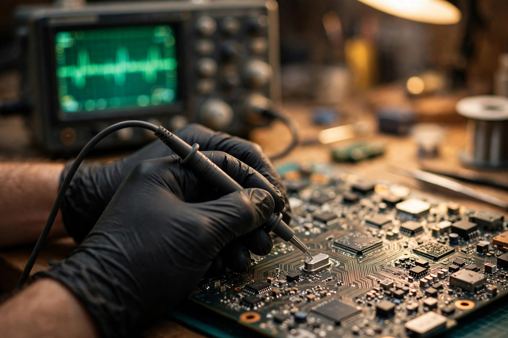
A laptop can have power, a lit indicator, and a spinning fan, yet show a completely black screen without even a brand logo. Or it can boot, then freeze without warning, restart on its own, recognise a USB device only intermittently, or produce intermittent audio pops. Or the same machine can boot on the first try on one day and need several attempts on the next, behaving differently when cold and when warm. Many users first suspect the power supply, memory, graphics card, or Windows, and rush to replace parts or reinstall the system. But one class of problem sits in none of those places. It sits in a deeper layer: the laptop clock system. The CPU, chipset, PCIe devices, USB controllers, and display and audio engines all depend on a synchronised, stable, recognisable clock before they can work together. When the clock goes wrong, the machine produces a set of symptoms that look unrelated. This guide covers that clock system: why a reference crystal fails, how a clock generator distributes one reference frequency into many clock domains, the eight layers where failure can sit, how to exclude faults layer by layer across three scenarios — normal power rails but no clock, frequency drift, and one missing clock domain — why measurement itself can kill the circuit being measured, how to separate the main clock tree from the 32.768 kHz real-time clock, why this fault is so easily misdiagnosed as a power-sequencing, PCH, Intel ME, BIOS, or CMOS battery problem, and how Hong Kong humidity and commuting vibration should — and should not — feature in repair, replacement, and upgrade decisions. All internal measurement and soldering work belongs to professional diagnosis. What a reader can do is limited to external observation, symptom records, cross-testing, and data backup.
Crystal, clock generator, RTC: three different things
Before discussing clock failure, three frequently confused items must be separated, or every later sentence will be misaligned.
First, the crystal. A crystal is a quartz crystal resonator that provides one original reference frequency. By itself it does not generate the many clocks of a system. It only provides a stable starting point. Frequency multiplication, division, and distribution are all done by the circuits that follow it.
Second, the clock generator. A clock generator is a clock synthesiser chip containing a phase-locked loop, or PLL. It takes the reference frequency and, through multiplication and division, produces the separate clocks the CPU, PCIe, USB, display, and other blocks each require, with low jitter and low skew. Older platforms mostly used an external clock generator chip. Newer platforms integrate much of the clock circuitry inside the CPU or PCH, in what is called an integrated clock circuit, or ICC. Whether external or integrated, the division of labour is the same: one reference source, processed by PLLs, distributed as many outputs.
Third, the RTC crystal. The RTC crystal, typically 32.768 kHz, serves the real-time clock, or RTC, maintaining timekeeping while the system is powered off. It is a different circuit from the main clock tree, with a different frequency, power level, power domain, and failure behaviour, as detailed in the RTC section below. Writing that "the time keeps going wrong, so the main crystal must be broken", or that "the machine will not boot, so the RTC battery must be flat", both confuse this division of labour.
One sentence sets the tone: clock generator or crystal failure belongs to the deeper class of motherboard-level faults. It does not necessarily leave the whole machine without power. Instead it leaves components without a synchronised, stable, recognisable clock, which is why the symptoms look unrelated. No single symptom can convict the clock system. More common layers must be excluded first, and the clock itself must then be confirmed by measurement.
The clock tree: from reference crystal to every clock domain
What follows is a framework in words, not a claim that every laptop shares one diagram. Laptop clock architecture varies enormously by generation. Actual frequencies, output counts, and integration levels must be checked against the schematic, boardview, or manufacturer documentation of the specific machine.
A reference crystal, with common designs including 24 MHz, 25 MHz, and 38.4 MHz depending on platform, and with 14.31818 MHz appearing in older motherboard examples, feeds a clock generator chip or the internal clock circuitry of the CPU or PCH. Internal PLLs perform multiplication, division, locking, and spread-spectrum processing, and the resulting clocks are then distributed to each domain, with clock buffers copying and fanning out one reference to several devices. Independent of the main clock tree, a separate 32.768 kHz RTC circuit maintains timekeeping while power is off.
An external clock generator on an older platform is a central distribution station. Early PC clock synthesiser examples show that every output frequency can be derived from a single crystal input, with two internal PLLs generating the CPU clock and other clocks separately, the PCI clock then being divided down from the CPU clock, and the PLLs needing a lock stabilisation time before lock is achieved. Later CK505 and CK410 generation parts, aimed at Intel platforms, integrated voltage regulation and differential output termination resistors, with rugged notebooks among the target applications. The point is not to memorise part numbers. It is to understand that an external clock chip itself has power supplies, decoupling, a PLL, output-enable pins, and configuration pins, and a fault in any one of them produces the pattern "crystal present, but no output".
Newer platforms move in the opposite direction: the clock is integrated into the processor and PCH. Intel Core Ultra 200S series documentation states explicitly that the processor contains a PLL that generates the processor reference clock from a fixed crystal clock, and that this reference clock is also called the Base Clock, or BCLK. Integrating the BCLK PLL inside the processor chip gives a cleaner clock at lower power. Intel 600 series and 700 series PCH documentation both carry a separate system clocks chapter and a separate real-time clock chapter, showing that system clocks and the RTC are separate functional blocks. The 600 series documentation also describes dynamic 38.4 MHz clock control, which is itself proof that a new platform reference frequency is not necessarily 24 MHz. Writing only "24 MHz main crystal" without adding "depending on platform" would mislead owners of newer models.
The table below maps each clock domain to its failure behaviour. The "typical behaviour" column is mechanism-level inference, not case statistics and not a diagnostic standard.
| Clock domain | Typical form, depending on platform | Typical behaviour when it fails, by mechanism |
|---|---|---|
| CPU BCLK | Processor reference clock, derived from a crystal by an internal PLL | Whole machine fails to boot, stuck at the earliest stage, no display; the fan may spin and power rails may be normal, but the CPU cannot execute its first instruction |
| PCH internal clock | Internal PCH PLL and system clocks | Boot sequencing stalls, broad PCH function abnormality, no response on related buses |
| PCIe reference clock | 100 MHz differential output, named CLKOUT_PCIE_P/N, spread-spectrum capable | One PCIe device disappears, for example a discrete graphics card, solid-state drive, or wireless card; link training fails, speed drops, or the link is unstable; the rest of the system may boot normally |
| USB, SATA, and other peripheral clocks | Historically derived from the same reference, for example 48 MHz USB and 24 MHz designs | One peripheral works intermittently, transfer errors occur, devices repeatedly disconnect; do not assume "a USB problem means a USB crystal is broken", since most platforms have no independent USB crystal |
| Display and audio clocks | Derived from PLLs, the display engine, or the audio engine | Garbled display, no display, audio pops or dropouts, while the system itself may already have booted; display and audio power and driver problems must be excluded first |
| Clock buffer output | One reference fanned out to several devices; some buffers block differential output until the PLL is locked | Only the devices behind that buffer fail; the generator output is normal, but the clock never reaches the device; a supply or output-enable fault can remove a whole output group; blocking output before PLL lock is normal protection behaviour, not a fault |
| RTC 32.768 kHz | Independent low-power clock, see the RTC section | See the RTC section; it does not belong to the main clock tree |
Why crystals fail: seven mechanisms
Crystal failure is rarely a sudden death with no warning. The more common picture is that start-up margin — negative resistance and gain margin — is gradually eaten away to a critical point, after which temperature, humidity, vibration, power, or a solder joint triggers the failure. The seven mechanisms below are stated with their evidence status, because mechanism and certainty are different things.
First, ageing and drift. Ageing of a quartz crystal means that, even in a constant environment, frequency still changes permanently over time, through internal physical change in the quartz lattice, contamination, mechanical stress, and similar causes. The change is logarithmic: the largest change comes early and then tapers. Generic crystal specification guidance gives, by way of example, first-year values of a few parts per million and a ten-year accumulation on the order of ten parts per million. This is a specification example, not a laptop failure rate, and not a claim that every laptop crystal must drift by those amounts. For a laptop, the significance is that a small drift need not kill the machine outright, but when added to temperature drift, load-capacitance error, and rising equivalent series resistance, the total error budget is consumed, and a previously passing circuit falls into start-up failure or marginal timing. Three budget items must be kept separate: frequency tolerance, temperature stability, and ageing. They must not be merged into one number.
Second, moisture and seal failure. A crystal package is filled with dry inert gas. A cracked ceramic package, damaged glass-to-metal seal, or excessively bent lead can break the seal, after which atmospheric moisture and contamination enter and performance degrades rapidly. A small number of oscillators are moisture sensitive: absorbed moisture can expand into vapour during reflow soldering and crack the package permanently. The relevant sensitivity is expressed as a moisture sensitivity level under JEDEC J-STD-020. In an assembled laptop, moisture more commonly shows up not as "water inside the crystal" but as pad oxidation, increased leakage paths, and changed effective load capacitance, which reduce start-up margin. Leakage and pad oxidation in humid conditions are listed in repair guidance as causes of start-up failure.
Third, shock, vibration, and board flex. Excessive mechanical shock can change electrical characteristics, most commonly frequency. A severe drop can crack the quartz blank itself. A ceramic package can also crack and lose its seal. More troublesome is the "half-cracked" state: an internal joint partly cracked, lowering the quality factor, making amplitude vary, and producing amplitude jumps on light touch or tapping. The outside may look normal, and only temperature change or vibration exposes the fault. Board flex can also tear pad patterns, break lead metal, crack solder joints, and damage seals. A mounting position in a high-flex region of the board carries higher risk.
Fourth, solder cracks, cold joints, and joint oxidation. Cold joints, solder bridges, oxidised leads, and reflow temperatures beyond specification can all break the oscillation loop. Reflow overheating can damage the internal chip and raise equivalent series resistance sharply so that oscillation becomes impossible. With long-term thermal expansion and contraction plus carrying flex, the small solder joints around a crystal and clock chip readily develop micro-cracks, with symptoms of intermittent operation, failure to boot when cold, booting only when warm, or booting when a certain board area is lightly pressed. Such symptoms cannot be summarised as "the crystal is broken". They require distinguishing the crystal itself, the joint, and the trace or via.
Fifth, load-capacitance drift and mismatch. A parallel-resonant crystal must operate at its specified load capacitance, or CL. The CL actually provided by a circuit is made up of external capacitors, trace stray capacitance, and internal chip capacitance, with common nominal values such as 12 pF, 18 pF, 20 pF, and 30 pF depending on the crystal model. The concept is: CL is approximately the stray capacitance, about 3 to 5 pF, plus the series combination of the two external capacitors. If CL is too large, frequency shifts low; if too small, frequency shifts high; extreme mismatch can prevent oscillation entirely. Capacitors themselves also age, vary with temperature, and leak when damp. If the original design used a material with larger temperature drift, or a capacitor value drifts, frequency follows. Repair guidance recommends low-temperature-drift, high-precision capacitors for matching, but that is a design-level recommendation. It does not mean a repairer may freely change values. Values must follow the original schematic.
Sixth, rising equivalent series resistance, or ESR. ESR is the internal loss of a crystal at resonance. The higher the ESR, the more drive the oscillation circuit must provide. Excessive ESR causes slow start-up, excessively long start-up time, or complete failure to start. Poor-quality crystals, cutting-angle deviation, uneven electrode plating, inadequate sealing, internal cracks, or contamination can all raise ESR abnormally and lower the quality factor. The key quantitative concept comes from manufacturer application notes and must be labelled by its scope: a note on oscillator design for a specific wireless microcontroller family states that, for reliable start-up, the magnitude of the circuit negative resistance at initial start-up should be at least 3 times the ESR, with 10 times initially and 5 times in steady state suggested for automotive use. Another application note gives a rule that if negative-resistance magnitude is below 2 times the maximum ESR, the crystal or load capacitance should be changed. A measurement method using a series variable resistor to find the oscillation-stop point computes a circuit margin, with above 10 described as ideal, 5 to 10 acceptable, and below 5 at risk of start-up failure. The principle transfers as mechanism explanation, but the numbers are not a laptop PCH standard. The diagnostic lesson for laptops is that rising ESR does not necessarily kill a machine immediately. It first appears as difficult cold start-up, start-up only when warm, or intermittent start-up. ESR must be measured off-line or with a suitable instrument. A multimeter resistance range cannot judge whether a crystal is good.
Seventh, start-up failure. Oscillation requires three conditions at once: sufficient loop gain, correct load, and sufficiently low parasitic loss. If any one is insufficient, the result is slow, intermittent, or absent start-up. A common trigger combination is rising ESR plus oversized CL plus long traces, high-speed lines under the crystal, proximity to power or heating components, plus supply noise and probe loading. Each item alone may pass, and only together do they cross the critical point. That is exactly why "a new crystal did not fix it" and "touching it fixes it, but refitting the case breaks it again" happen. Overdrive is the opposite extreme: drive power beyond the crystal limit can cause long-term drift, micro-cracks, and accelerated ageing. Increasing drive must not be used as a universal repair.
A manufacturer classification gives a useful skeleton: oscillation-circuit failure can be grouped into four categories — no oscillation or oscillation stopping midway, oscillation frequency deviating from nominal, insufficient oscillation amplitude, and abnormal frequency-temperature behaviour. These four explain why clock disease has more than one face: not every clock fault is "no clock at all". More often it is "present, but inaccurate, unstable, or intermittent".
Symptom map: what the user sees, and what it may mean
Each row below separates what the user sees, the timing mechanism, and the more common causes that must be excluded first. No row may be read as "this symptom means the clock generator is broken".
Power on, no display: pressing power gives lights and fan noise, or a fan that spins briefly and stops, while the screen stays black, no brand logo appears, and an external display shows no signal. The clock explanation is that if the main reference clock does not start, the CPU and PCH receive no usable clock, and power-on self-test cannot advance to display initialisation. Motherboard clock-circuit guidance likewise notes that an abnormal CPU clock can mean no reset and no POST codes. What must be excluded first: power supply and charger, memory, display panel and cable, display output settings, and BIOS damage. An official no-display troubleshooting order is itself power, CPU, memory, graphics card, display, minimal system, then clearing CMOS. The clock is a deeper motherboard-level check, not the first step.
Stuck at the logo or stuck in POST: the brand logo appears and then freezes, or the machine repeatedly restarts without ever entering the system. Sometimes removing all external devices lets it pass the logo. The clock explanation belongs to the grey zone of "some clocks present, some clocks unstable": POST advances to a stage that needs a particular clock domain, such as storage, USB, or PCIe enumeration, and stalls there. What must be excluded first: external devices disturbing the boot order, a wrong boot order, a solid-state drive not detected or damaged, and unstable BIOS settings. A clock suspicion clue is only a clue: an inconsistent stall point, different cold and warm behaviour on the same machine, or a stall that changes when external devices are unplugged without a fixed pattern. All of these point to marginal timing and still require measurement before any diagnosis.
Random freezes, restarts, or blue screens: the machine suddenly locks with mouse and keyboard unresponsive, so only a long power press shuts it down; or it restarts without warning; or it occasionally blue-screens. After restarting it may be immediately normal, or it may fail repeatedly. The clock explanation is that clock jitter, frequency offset, or intermittent oscillation stoppage misaligns communication timing between the CPU and peripherals, producing application crashes, timing failures, and whole-machine stalls. One blue-screen name trap must be stated plainly: Windows CLOCK_WATCHDOG_TIMEOUT, code 0x00000101, contains the word "clock", but the official definition is that, in a multiprocessor system, a secondary processor did not receive the expected clock interrupt within the allocated time — that is, the processor did not respond or deadlocked — with common causes including drivers, overclocking, firmware, memory, and overheating. It does not mean the clock generator chip is damaged. What must be excluded first: overheating, memory, driver and system updates, unstable power, and solid-state drive health.
USB timing anomalies: the same USB device is sometimes recognised and sometimes not; large transfers disconnect midway or vary wildly in speed; changing ports or cables changes the behaviour without a pattern, while the device itself works normally on another machine. The clock explanation is that USB, Ethernet, Wi-Fi, and Bluetooth interfaces all depend on precise timing, and low RMS jitter is a design requirement. USB application documentation likewise states that USB applications require a 25.000 MHz reference clock with total tolerance of plus or minus 100 ppm, and that an oscillator with poor jitter performance can introduce data-integrity problems under particular temperature conditions. What must be excluded first, and is usually more common: physically damaged USB cables or ports, insufficient power (especially for external drives and hubs), drivers, device firmware, and system power-management settings. Clock suspicion should only rise in priority when several devices and several ports show timing-type anomalies at once and swapping cables and devices still shows no fixed pattern. The right wording is "marginal timing", not "USB is broken": with a slightly off clock, low-speed or small transfers may still pass, and only high-speed or continuous transfers expose the fault. That is an inferential explanation and must be labelled as requiring measurement and cross-testing.
Audio pops and drift: speakers or headphones produce intermittent clicks and pops or dropouts; recordings or playback slowly drift out of tune or out of sync; the problem is especially obvious with an external USB audio interface. Two layers must not be confused. The first and most common layer is software and settings: mismatched sample rates, an un-unified master clock, or a buffer too small to keep up all produce pops or dropouts. Professional troubleshooting guidance states that in a complex digital setup, one device must act as master clock and the rest as slaves, or regular ticks will be heard, and that a buffer too small leaves gaps in data, which are heard as pops. The second layer is hardware clocking: the sampling clock is divided down from a high-stability crystal; small frequency wobble in the crystal is called jitter, rising jitter blurs stereo positioning and lowers low-level resolution, and a slowly drifting sample rate changes playback pitch. What must be excluded first: drivers, sample-rate settings (44.1 kHz versus 48 kHz), buffer size, cables and connectors, and excessive CPU load starving the audio buffer. The conclusion must be: audio pops are in the great majority of cases not a broken motherboard clock generator. Only when built-in audio, external audio, and different software all show load-independent drift or pops, and the settings layer has been excluded, is motherboard timing worth suspecting.
Intermittent behaviour is the most diagnostically valuable and most easily misread group, and it must be split into four subtypes. Hot failure with cold normality: the machine is normal just after booting, then after a period of use begins to freeze, disconnect USB devices, or lose display, and recovers after cooling down. Rising temperature lowers oscillator gain, shifts crystal frequency, and changes ESR and load-capacitance behaviour. A classic published case is a UART crystal whose waveform distorted progressively with rising temperature until it was captured by a neighbouring strong clock, a phenomenon called injection locking, at which point communication stopped. Cold failure with warm normality: in winter or in an air-conditioned room, the machine fails to boot or stalls when first switched on, then works normally once warm, or needs several attempts. At low temperature, crystal internal resistance rises and capacitance values change, making start-up conditions marginal. Mixed success at switch-on: on the same day, sometimes one attempt boots and sometimes several are needed, with no clear hot or cold pattern. This is marginal start-up: load-capacitance mismatch, high ESR, or poor joint contact makes every start-up a gamble. Engineering discussion cites a prototype that started when touched by hand but failed in production, a stray-capacitance case of the same marginal-start-up class. Vibration or movement triggered: moving the machine, closing and reopening it, or taking it out of a backpack triggers the fault, while it works normally on a still desk. Intermittent continuity from cracked joints breaks the clock loop, stopping oscillation or jumping frequency. Hot and cold patterns are the most valuable user evidence for recording, but a hot or cold pattern alone does not equal clock disease. Overheating protection, battery, power, and memory also show hot and cold behaviour. The article should teach readers to record the pattern, not to diagnose from it.
Need a laptop repair expert?
Free diagnosis · Transparent pricing · No fix, no fee · 180-day warranty
Eight failure layers
The principle is to verify layer by layer from the source downstream. Until an upstream layer is confirmed normal, a downstream layer must not be condemned.
| Layer | Possible causes | Typical symptom differences | Key distinguishing point |
|---|---|---|---|
| 1. Crystal itself | Cracked quartz blank, half-cracked internal joint, seal failure, excessive ESR, ageing plus temperature stacking | No oscillation at all; or no oscillation when cold but oscillation when warm; or intermittent oscillation with unstable amplitude | Off-line measurement or substitution with a crystal of identical specification has reference value, and only with the same frequency, same CL, and same package; probing crystal pins in circuit is disturbed by probe loading |
| 2. Load capacitors | Capacitor value drift, wrong value, leakage, cracked joint, changed stray capacitance from traces or repair residue | Frequency pulled away from nominal, slow start-up, intermittent start-up; sometimes touching a capacitor starts oscillation | Frequency error direction corresponds to CL error direction: larger CL means lower frequency, smaller CL means higher frequency; capacitor values must not be changed up or down at will |
| 3. Clock generator power supply | Missing main supply, shorted or open decoupling capacitor, one supply group missing | Main board rails normal but the clock chip has no output at all; or only some output groups disappear | Each supply pin group of the clock chip must be measured; measuring only the board 3.3 V or 5 V cannot establish that power is normal; older generation documentation shows several independent supply groups |
| 4. Clock generator itself and PLL | Chip damage, PLL failure to lock, configuration or output-enable pin error, internal regulator failure | Reference input and power present, but no output or wrong output frequency; or PLL never locked, so buffers block output | Check output-enable and configuration pin levels, PLL lock indication where present, and whether the reference input reaches the chip; suspect the chip itself only after power and crystal are excluded |
| 5. Clock buffer | Buffer supply missing, output-enable error, open output termination resistor, one output group damaged | Only the devices behind that buffer fail; generator output is normal, but the clock disappears before reaching the device | Measure on both the input and output sides of the buffer, to locate the break before or after the buffer |
| 6. PCH internal PLL | PCH supply or clock input abnormality, PCH damage, internal PLL failure to lock | System clocks broadly abnormal, while the external reference may be normal; often accompanied by other PCH function abnormalities | Combine PCH supply, reset, and related bus signals for judgement; do not replace the PCH on "no clock" alone |
| 7. Traces, solder joints, vias | Broken trace, cracked via, micro-cracked joint, interference source under a trace, open termination resistor | Intermittent, affected by pressing or board flex, temperature sensitive; one domain alone disappears while others stay normal | Visual inspection plus microscopy plus press testing plus trace continuity checks; a differential pair needs both positive and negative lines checked for symmetric damage |
| 8. Destination device itself | Device damage, device-side termination or coupling problem | Clock reaches the device input pin, but the device still does not respond | Device damage must not be misjudged as a clock source problem |
Three scenarios, layered exclusion
The critical dividing line in diagnosis is not "is there power". It is: are the power rails normal, has the reference crystal started, has the clock generator or PCH internal PLL locked and produced output, and does every output reach its destination. Skipping any middle layer and going straight to board replacement, BIOS reflashing, or blaming the PCH or Intel ME is a high-risk misdiagnosis move.
Scenario A: power rails normal, but no clock, whole machine fails to boot. First, confirm the main power rails against the schematic — not just one or two groups — and confirm that every supply group of the clock chip is present. Second, confirm whether the reference crystal has started, preferably by measuring a buffered output or a clock chip output, not by probing crystal pins directly. Third, confirm that the output-enable and configuration pin levels of the clock chip are correct, and confirm PLL lock where a lock indication or output-blocking behaviour exists. Fourth, confirm that BCLK or the PCH clock reaches the CPU or PCH. Fifth, only if all of the above are normal, move to reset sequencing, BIOS, Intel ME, CPU, and PCH investigation. The order must not be reversed.
Scenario B: clock present, but frequency drifting or jitter excessive. First, exclude measurement error: probe, ground-lead length, spread spectrum, and frequency-counter gate time. Second, check load-capacitance mismatch or drift, crystal ageing plus temperature stacking, excessive supply noise, and trace interference. Third, if the frequency error is a fixed offset, suspect load capacitance first; if it drifts with temperature or time, suspect crystal ageing, capacitor temperature drift, or rising ESR first. Do not dismiss a small frequency difference as irrelevant: high-speed interfaces such as PCIe have reference-clock accuracy and jitter specifications, and exceeding them can appear as an unstable link rather than immediate death.
Scenario C: one clock domain missing, others normal. First, locate the break segment by segment: generator output, buffer input, buffer output, destination input. Second, if buffer input is normal but output is absent, check buffer supply, output enable, and termination. If the generator output for that domain is itself absent, check generator configuration — some outputs can be disabled by bus or strap configuration — and that supply group. Third, if the clock reaches the destination but the device still does not respond, investigate the device itself. Do not go back and replace the clock chip.
This is why the working principle is worth memorising: having power does not mean having a clock; having a clock does not mean the frequency is correct; having one clock domain does not mean all domains are normal; and before flashing BIOS, first ask whether BCLK has arrived.
Measurement traps: do not probe high-impedance crystal pins directly
This is the most important section of the guide, because measurement itself can kill the object being measured.
Instrument manufacturer documentation uses a crystal circuit as its explicit example: when a probe input resistance of 10 Mohm sits in parallel with a 10 Mohm resistor in the oscillation circuit, a voltage divider is formed, the oscillator receives only half the expected voltage, and intermittent operation or complete oscillation stoppage can result. Probe capacitance in parallel with the resonant circuit also changes the resonant frequency. Practitioner discussion notes that even a 10x probe can overload a crystal, turning a normal frequency reading into a false reading of a few hundred hertz to around a kilohertz. Some repairers report that a weakly starting crystal "dies the moment any probe touches it", and that only a 100x low-capacitance probe, about 4 to 5.5 pF, leaves the oscillation alive, or that non-contact sensing with an EMC probe or spectrum analyser should be used for a qualitative "is it oscillating" judgement. The consensus statement in another discussion is: do not measure directly across the crystal, because loading changes frequency and can even stop oscillation; measure the first buffered output instead; if surrounding voltages are normal but there is no output, the crystal itself is the suspect.
The conclusion is one sentence: crystal pins are not a measurement point. Buffered outputs are.
The correct measurement checklist is as follows. Prefer a 10x or higher-ratio low-capacitance probe, and never use a 1x probe on crystal-related nodes. A 1x probe capacitance of about 40 to 60 pF is far larger than crystal load-capacitance levels. Keep ground leads as short as possible: a long ground clip forms a loop antenna, introduces noise, and changes the measurement. For high-frequency measurement, use a short ground spring or a nearby ground point. When measuring a differential clock, such as a 100 MHz PCIe differential output, understand both the positive and negative lines differentially. Do not ground one line casually with a single-ended probe and draw conclusions. Without a differential probe, use the combination of "does the buffer output show a differential waveform" plus "what is the destination link state" as indirect evidence, and hand the work to professional repair. A frequency counter is only suitable for buffered, low-impedance outputs. Connecting a frequency counter directly to crystal pins adds load in the same way, and the result cannot be trusted. The 32.768 kHz RTC crystal runs at extremely low power, so probe loading affects it even more. A low-power crystal that stops oscillating when an instrument is connected is a known phenomenon, and it must not be taken as proof that the crystal is already broken.
Live measurement carries its own risk: a probe slipping on a powered board can short adjacent pins and destroy the clock chip, PCH, or CPU. Probing a high-density board while powered, without electrostatic protection, microscopy, and a schematic, carries risk far greater than any benefit. That is why the layered exclusion flow in this guide is repairer diagnostic logic. For an ordinary user, external inspection, confirming power and external devices, and recording symptoms — cold or warm, pressing, intermittent pattern — is already enough. After that, the machine should go to a repairer with a boardview, oscilloscope, hot-air station, and same-specification parts.
What must not be done should be stated explicitly: do not use a multimeter resistance or continuity range to judge a crystal in circuit; do not swap in a crystal of a different frequency or different load capacitance just to try; do not short clock output pins; do not disassemble a board before power is disconnected and discharged; and do not reflash BIOS or Intel ME firmware just to try, since a wrong flash can turn a repairable board into a bricked board.
RTC 32.768 kHz: separate from the CMOS battery and from the main crystal
Intel PCH documentation lists system clocks and the real-time clock as separate chapters, and that structure is itself official evidence of the division. The RTC crystal belongs to the PCH real-time clock functional block and maintains timekeeping while the system is powered off. The main clock tree synchronises the CPU, PCH, PCIe, and other blocks after boot. The two differ completely in frequency, power, power domain, and failure behaviour.
The three-way comparison table below is the core of this section.
| Item | Supply and function | Typical failure behaviour | Diagnostic point |
|---|---|---|---|
| CMOS and RTC battery, commonly CR2032 or a soldered cell | Powers the RTC and CMOS memory while power is off; after boot, a standby supply or the main battery usually takes over through a diode OR arrangement, and the cell itself is not charged; a CR2032 cell cannot be recharged | Date and time reset to defaults after every power loss, CMOS checksum error, boot prompt about lost settings; but with power connected, the machine usually still boots normally | Measure battery voltage and the RTC supply rail; if time is lost on every power loss but booting is normal, suspect the battery or RTC supply path first, not the main crystal |
| RTC 32.768 kHz crystal and RTC oscillation circuit | Generates the RTC time base; needs the RTC supply rail to be maintained | Time runs slow, fast, or stops, even without power loss; RTC function abnormality; in severe cases boot sequencing can be affected, but that is not the same as missing BCLK | The RTC supply rail and 32.768 kHz start-up need measurement, and are equally affected by probe loading; a crystal problem cannot be treated by replacing the battery |
| Main crystal, clock generator, BCLK | Synchronisation reference for the whole system after boot | Whole machine fails to boot, stalls at an early stage, PCIe, USB, and other subsystems fail | When battery replacement, clearing CMOS settings, and BIOS reflashing all make no difference, only then enter main clock-tree layered exclusion; main clock failure are not "CMOS battery flat" |
A one-sentence separation rule, with a "generally speaking" qualifier: time lost only on power loss, with normal booting, points first to the battery or RTC supply. No boot or a stall despite power, with battery replacement and CMOS clearing making no difference, points first to the main clock tree, power sequencing, reset, and PCH or CPU paths, not back to the battery. Time running inaccurately, slow or stopped even without power loss, makes the RTC oscillation circuit itself — crystal, load capacitors, RTC supply — worth suspecting, subject to professional measurement.
Common misdiagnoses: power sequencing, PCH, Intel ME, BIOS, and more
The misdiagnosis table below is the core deliverable of this section. A distinguishing clue in the table is not a diagnosis. Diagnosis still requires measurement or cross-testing.
| Misdiagnosis | Why the confusion happens | How to separate it, from a clock perspective |
|---|---|---|
| Power sequencing problem | No clock-chip output looks very similar to "power never started"; and a missing clock-chip supply is itself a power problem | Measure each supply pin group of the clock chip: if main rails are normal but one clock-chip supply group is missing, it is a power distribution problem; if every supply group is present but there is still no output, move to crystal, chip, and PLL investigation |
| PCH damage | A PCH without a clock looks the same as a damaged PCH: stalled, no display, broad functional abnormality | First confirm whether the PCH clock input arrives, and whether PCH supply and reset are normal; before the clock is shown to arrive, the PCH itself must not be condemned; PCH replacement is high-level soldering work, and a wrong replacement is extremely costly |
| Intel ME damage or firmware damage | ME abnormality can also appear as a boot stall, an approximately 30-minute shutdown, or a BIOS display showing an abnormal ME version, similar to the stall appearance of clock failure | ME problems often carry their own features, such as an abnormal ME version, an approximately 30-minute timed shutdown, or ME recovery mode, and the ME firmware repair path is rewriting the ME region, which needs a programmer and correct firmware and has nothing to do with the clock tree; if clock measurement has already proven BCLK absent, handle the clock first, not the ME; the scope of the approximately 30-minute pattern must be checked against the model, and it are not "every Intel machine with broken ME shuts down after 30 minutes" |
| BIOS damage or BIOS setting error | "Cannot boot means BIOS is broken" is the most intuitive and most dangerous jump; BIOS reflashing looks like a low-cost attempt, so people try it first | If the clock tree has not started, the CPU cannot execute even the first BIOS instruction, so reflashing BIOS cannot make the clock start; before reflashing, clock and reset must first be confirmed normal, or the attempt only wastes one flash risk |
| Reflashing BIOS fails, then blaming the CPU | After a BIOS flash the screen is still blank, so suspicion moves to the CPU, but a CPU without a clock cannot work either | General repair guidance is to start from the CPU input signals — power, clock, reset — rather than replacing the CPU first; replacing a CPU without a clock is equally ineffective |
| Replacing the board instead of diagnosing | Without layered localisation, "the board is broken" is declared and board replacement substitutes for diagnosis | If the fault sits only in one buffer output or one trace, replacing the buffer or repairing the trace costs far less than replacing the board; board replacement should be supported by layered measurement records |
A layered investigation order, as logic rather than repair steps, is: external devices, power, and display output, which are fastest and safest; then BIOS setting reset to defaults and boot order; then memory and solid-state drive cross-testing; then CMOS and RTC battery and time-retention testing; then Intel ME status checks, including the BIOS version display and the approximately 30-minute pattern; then power sequencing and supply-group measurement at repair level; then clock reference and output measurement at repair level; then PCH and other motherboard function measurement at repair level. The rationale is outside-to-inside, software-to-hardware, and common-to-rare, not suspicion-to-diagnosis.
Hong Kong context: humidity and commuting vibration, stated conservatively
On humidity, start with the baseline, then the mechanism, and do not jump to a causal verdict. Hong Kong Observatory climate normals for 1971 to 2000 show average relative humidity of 82 percent in March, 83 percent in April, and 84 percent in May, with an annual average of 78 percent. Average dew points for March to May are 15.5 degrees, 19.4 degrees, and 22.7 degrees respectively. In other words, around the spring humidity season, once the indoor-outdoor temperature difference widens, cold surfaces very easily fall below the dew point. Observatory popular science explains that as air temperature falls, saturation vapour pressure falls, and when temperature reaches the dew point, air becomes saturated and vapour condenses into droplets. Applied to a laptop: moving from an air-conditioned room, where the body and board are relatively cold, to humid outdoors, or bringing a machine indoors from humid outdoors and switching it on, can condense moisture on cold surfaces or local cold spots on the board. Electronics corrosion research also notes that infrared imaging can show local cold spots on a powered board as especially prone to condensation and corrosion.
The actual damage mechanism of moisture must be written without exaggeration: moisture plus ionic residue, such as flux residue, sweat, and dust, forms a conductive water film on the printed circuit board surface, causing leakage current, short circuits, electrochemical migration, rising contact resistance, and intermittent failure. When moisture cycling and condensation form directly on component surfaces, corrosion and leakage risk are highest. Under high humidity, electrochemical migration can progress from leakage to intermittent failure and then to a hard short. One point is especially relevant to the clock loop: leakage or parasitic capacitance change between the two crystal pins directly changes the oscillation-loop load condition and makes start-up marginal. A "sometimes good, sometimes bad" pattern in the humid season is consistent with this mechanism, but note that consistency is not proof, and that inspection is required for confirmation.
Usable, non-exaggerated Hong Kong advice is as follows. During the spring humidity days when walls run with water, do not switch on a machine immediately after bringing it from an air-conditioned room outdoors and back. Leave it in a ventilated place to return to room temperature and wipe the surface dry, and wait until the body temperature is close to room temperature before switching on. Leaving a machine long term near a window, a bathroom doorway, or directly in an air-conditioner draught subjects it to humidity plus temperature-difference cycling that accelerates solder-joint and contact ageing. That sentence is mechanism inference, not measured statistics. After water ingress, rain, or a spilled drink, "it dried out, so it is fine" is a misunderstanding: residue after the water dries can still conduct, and intermittent faults may appear days later. The machine needs inspection, and repeated powered trials must not be attempted.
On commuting vibration, the mechanism evidence is that solder-joint defect reviews note that cracks, voids, and intermetallic brittleness can pass factory testing and then fail in the field under thermal cycling or vibration, and that cold joints and joints with insufficient solder are especially prone to cracking under vibration. The Hong Kong translation is inference and must be labelled as such: a backpack without inner protection, a machine shaken during walking all day, or compression and impact in a crowded train all count as repeated small shocks plus bending stress. This is not one dramatic drop breaking a machine, but edge joints slowly cracking. Because crystal and load-capacitor parts are small with small joints, once a micro-crack appears, the symptom is "fails when moved, normal when still", matching the vibration subtype above. Exaggerated sentences should not be assumed, such as claiming train vibration breaks crystals or that one backpack drop breaks a clock chip. Vibration is an accelerating or triggering factor, not a single necessary cause. Whether there is a drop history is only a history-taking clue.
On local parts and repair reality, state principles only, without inventing part numbers, prices, or lead times: crystals and clock chips must be matched by individual model schematic for frequency, load capacitance, package, and supply. Some older models may be discontinued or hard to source, and repair feasibility must be assessed against the actual machine. No promise of "parts definitely available" should be made. A crystal or capacitor with wrong parameters can make the situation worse, so buying one online for self-replacement is not a recommended approach.
What users can do, and what must go to repair
Users can do the following without disassembly and without measurement. External-device exclusion: remove all USB devices, memory cards, external displays, and docking stations, and boot with only the original charger and built-in display, to see whether the symptom disappears or changes. Basic power and display confirmation: try another socket, check the charger light where present, and confirm the external display input source. Having lights but no display versus no response at all must be recorded distinctly. BIOS setting reset, only when the BIOS setup screen can be entered: use the key combination in the manufacturer manual to enter setup, select load defaults, save, and restart. Do not change overclocking or clock-related settings when unsure, and do not perform a BIOS update on low battery or under possibly unstable power. Pattern observation, using the record table below: record at least three to five failure episodes and hand them to the repairer. That is far more useful than "it keeps breaking". Data backup, while the machine still boots: back up important files as soon as intermittent symptoms appear. Do not wait until the machine cannot boot at all. Backup itself will not fix a clock, but it prevents a repair from becoming a data-rescue case.
The following must go to repair, and users must not attempt them. Disassembly, board removal, or desoldering any component, including crystals, load capacitors, clock chips, the PCH, and BIOS chips. The reasons are that a schematic and measurement confirmation are required, wrong parameters make things worse, and self-disassembly can affect later diagnostic judgement. Measuring clock waveforms or frequencies, which needs an oscilloscope or frequency counter with probe-loading effects considered. A multimeter cannot measure clock quality. Reflashing BIOS or Intel ME firmware, except through a manufacturer official recovery procedure. A wrong file or a power cut midway can leave a board unable to start at all. Repeated powered trials after water or moisture ingress, since power accelerates electrochemical migration and short circuits. The machine should be inspected first. For machines still within a warranty period, the manufacturer warranty or authorised repair route should be taken first, without self-disassembly. This is general advice only, by individual manufacturer terms, and no specific brand term should be written as fixed.
Warning signals for immediate stop and repair: a burning smell, smoke, a swollen battery, or abnormal body heat. Disconnect power immediately and do not attempt to boot again. No response at all even after changing the charger, or symptoms changing from intermittent to every time, also mean no more repeated forced restarts. Arrange inspection promptly, and back up first if the machine can still boot briefly.
The pre-repair record table is as follows.
| Record item | How to record it |
|---|---|
| Date and time, weather, indoor-outdoor temperature difference | For example, spring humidity season, switched on immediately after moving from an air-conditioned room outdoors |
| Cold or warm machine | Just booted, how long used before failure, whether cooling down restores operation |
| What was done before failure | BIOS or driver update, drop, water ingress, memory or solid-state drive added, charger changed |
| Symptom stage | No response, lights but no display, stuck at logo, freeze after entering the system, USB disconnection, audio pops |
| External device state | What was connected at the time, whether removing it changed anything |
| Restart behaviour | Boots first time, needs several attempts, recurs after about how long; note especially any approximately 30-minute pattern, see the Intel ME clue |
| Backup status | Whether backed up, and which files matter most |
Repair, replacement, or upgrade: a decision framework
The principle is that the decision is not simply "which is cheaper". It is three things together: how much longer the repaired machine can be used, whether further investment is still worthwhile, and how large the data risk is. Every price comparison below is subject to a written quote after inspection. No assumed numbers are used to fill the table.
Ask four questions before discussing options. First, how much useful life remains: daily documents, web use, and light work, or work software the machine can no longer keep up with. If a replacement is already planned, repairing the clock only to rescue data or to bridge a gap is a completely different decision. Second, are there other ageing problems besides the suspected clock fault: battery endurance, display, keyboard, solid-state drive health, cooling, and hinges. If several are ageing together, fixing one item alone may not restore overall reliability. Third, is data backed up: without a backup plus intermittent booting, the priority should be protecting data first and discussing repair options second. With a backup, options can be compared more calmly. Fourth, what is the warranty or manufacturer support status: within warranty, the manufacturer route should come first. Only after warranty should independent motherboard-level repair, board replacement, and machine replacement be compared.
| Option | When to consider it | What to ask clearly | Risks and limits |
|---|---|---|---|
| Motherboard-level repair, including replacing a crystal, capacitor, or clock chip, or repairing joints | Other parts of the machine are in good condition, parts are still available or repairable for the model, and the user wants to keep the original machine and settings | What the written post-inspection quote covers, including inspection, parts, labour, warranty arrangements, whether parts are new or salvaged, and how charges work if repair fails | Some models may have no parts; severe joint or board-layer damage may not stay stable long term; accept that repairability is only known after inspection |
| Board replacement | The board is damaged in many places, a key part such as a clock chip or PCH cannot be repaired separately, but other parts of the machine are still new | The board-replacement quote in writing, warranty arrangements after replacement, and whether data is affected, for example if a solid-state drive sits on the board or encryption is bound to the board, which needs a specific question | This is generally the option with the largest upfront investment of the three, as a structural description, not a specific price comparison; old-board recycling and data handling need clear questions |
| Machine replacement, or upgrade | The machine is old, several ageing problems appear together, work requirements already exceed the old machine performance, or post-repair reliability remains doubtful | Whether new machine specifications match the work, old-machine data migration arrangements, and old-machine handling, including recycling or resale | Replacement does not necessarily mean good value: if the old machine has only a single crystal or capacitor problem and is otherwise in good condition, replacement is over-investment; conversely, with several ageing problems, replacement is cutting losses |
The following claims have no basis and should be avoided: "a broken crystal is cheap, just replace it", since there is no quoted basis and it ignores inspection and soldering cost; "a broken clock chip means the board must be replaced", since some cases can be repaired separately depending on model and inspection results; "an old machine is never worth repairing", since overall machine condition and user purpose matter; and "a new machine will definitely solve everything", since if the problem is an external device, a setting, or data migration, replacement may not solve it.
On fees, the only confirmed starting prices in the whole guide are for other repair items, for reference only, and must not be transferred to clock items: battery from HK$580, display from HK$1,280, motherboard chip-level from HK$880, and keyboard from HK$480. Crystal, load-capacitor, and clock-generator chip parts and repair costs, PCH replacement, board replacement, and machine replacement are all subject to a written quote after inspection. Motherboard chip-level from HK$880 are not a clock-chip replacement price or a PCH replacement price. It is only a confirmed starting price for one repair category, and it does not mean every motherboard-level repair costs that amount.
Honesty gaps: what is not proven must not be filled in
The following gaps must not be filled in during writing. First, no reliable prevalence data: no share of laptop faults attributable to clock generator or crystal failure, no common age distribution, and no common brand distribution were found. The guide must not carry quantitative descriptions, brand failure rates, or rankings. Second, no model comparison table: no specific laptop model clock-chip model, crystal frequency, or load-capacitance value was verified. No model table should be listed unless each model is later verified against its schematic. Third, the PCH heating case is weak evidence: PCH-related passages rest on second-hand case collections, not manufacturer documentation. If mentioned, they must be labelled as individual repair-case phenomena, not general diagnosis. Fourth, audio and USB clock attribution is weak: common causes of audio pops and USB dropouts far outnumber clock disease. The guide must place settings, drivers, cables, and power before the clock, and must not reverse the order. Fifth, Hong Kong local repair prices and lead times: apart from the four confirmed starting prices above, there are no local clock-repair quoted data. Every price statement must return to a written quote after inspection. Sixth, the scope of the Intel ME approximately 30-minute pattern: community replies address specific generations or situations. It are not applying to every Intel machine with ME failure. The guide should say it is one characteristic presentation, to be checked against the model.
Conclusion
Clock disease can rarely be summarised as one broken part. Crystal ageing, moisture, vibration, micro-cracked joints, load-capacitance drift, and rising equivalent series resistance each eat away at start-up margin. Missing clock-chip supply, a PLL that never locks, a buffer output that disappears, and a broken trace can each stop one layer or one domain. Humidity and drops are only general maintenance background, not diagnostic reasons. The safest order is always to record symptoms and before-and-after comparisons first, then do external exclusion and cross-testing, and only then let diagnosis narrow the range by the eight layers and the three scenarios. For diagnosis arrangements or fees, see Diagnostic Service and Pricing Reference, subject to a written quote after inspection.
Safety warning: live board measurement, disassembly, desoldering, and BIOS or Intel ME firmware reflashing all carry a risk of worsening damage or bricking the machine. Crystal pins are not a measurement point, and probe loading can stop a marginally starting circuit from oscillating. Do not disassemble the machine, measure clock waveforms, replace crystals or clock chips, or reflash firmware yourself. Hand all internal work to professional diagnosis, and back up important data before any work.
Safety warning: a BIOS screen is for read-only recording only. Do not change settings you are unsure about. Disassembly, battery removal, and shorting board jumpers can worsen damage, and readers must not attempt them.
Shop information: Room 1209, Daly Plaza, Shek Mun, Shatin, phone +852 2186 8010, WhatsApp +852 6558 6806, business hours 12:00–19:00.
If the machine already shows the symptoms above, first record the symptom pattern and the cold, warm, and vibration patterns, then enquire through Diagnostic Service, and see Pricing Reference for the fee structure.
Disclaimer: This article is for reference only. Actual conditions are subject to professional diagnosis results. Different models have different structures and original specifications, and handling should follow the written quote after inspection and professional advice.
Need Professional Laptop Repair?
Laptop King has 15+ years of repair experience in Shek Mun, Sha Tin. Free diagnosis, transparent pricing, no fix no fee. 180-day warranty for your peace of mind.