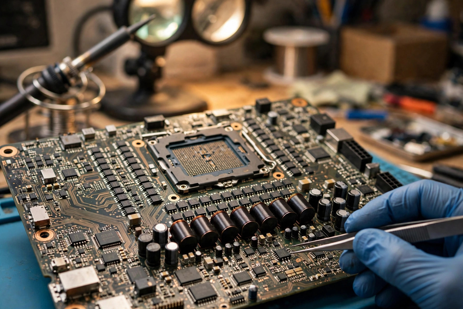
1. Scope First: This Article Covers Only the CPU VRM Layer
This article applies to one narrow situation: a laptop that is normal at idle but throttles, crashes, or shuts down once the processor is under heavy load, where the reader wants to understand how the supply layer fails, how layer-by-layer exclusion narrows suspicion, how to avoid common misdiagnoses, and what to record before inspection. The CPU VRM layer means the circuit that starts from the system main rail and, through a controller, switching devices, inductors, capacitors, a multiphase loop, a load line, and protection signals, converts a higher voltage into the low-voltage, high-current supply the processor core needs. This article explains how that circuit fails, how external comparisons narrow it, how to avoid misdiagnosis, and what the user layer can do.
The following layers appear only as boundary comparisons and are never expanded into the main body: the charging layer, the power-sequencing layer, the board short-circuit layer, the fan layer, the still-overheating-after-cleaning layer, the battery-not-detected layer, the display-artifact layer, the solder-joint layer, the controller layer, and the firmware-corruption layer. All of them return only in the boundary section, each in no more than three sentences. The cooling, system, driver, power-plan, input-supply, and processor-body layers appear in exclusion because exclusion exists precisely to separate which layer failed first, not to write that throttling proves supply failure.
The hard boundary is this: The user layer is limited to observation and recording without opening the machine: idle versus load comparisons, mains versus battery comparisons, power-plan and usage-context records, system-log observation, and temperature and monitoring-value observation and recording. Internal inspection belongs entirely to inspection. You must not open the machine yourself, remove the bottom cover, remove the display, unplug internal cables, inspect supply components, or replace supply components yourself. This guide contains no open-it-and-see instructions, and no measurement procedure, test-point guide, or waveform-reading tutorial either.
2. What a VRM Is: Why the Processor Needs Low Voltage and High Current
A VRM, a voltage regulator module, is the general name for a circuit that converts a higher direct-current supply voltage into the lower working voltage a processor needs, typically implemented as a switching buck converter because it is more efficient. In a laptop the scope must be narrowed: this article covers the processor core supply rail, not every voltage rail in the machine; other rails have their own supply designs, and conclusions about the core rail cannot be moved to all rails. It must also be stated that the processor itself contains a small amount of internal regulation supporting some internal rails, while the core rail remains an externally supplied, voltage-request-based, load-line supply; it should not be assumed that all processor power comes directly from the board supply. The core rail is mainly supplied by the board supply, individual internal rails may be shared by internal regulation, and the actual division follows that machine's design documents.
Why low voltage and high current follows from power arithmetic: power equals voltage times current, so at the same power, lower voltage requires higher current. As a purely arithmetic illustration, a core voltage of about 1 volt class against an adapter example of about 19 volts class differs greatly, so the same wattage implies a much larger core current; after conversion loss, the real input-to-output current relationship must be corrected for efficiency. That sentence states direction only and must never be turned into a specific wattage, current limit, or current-cap figure for any laptop, since those figures vary by machine and processor model and must follow that machine's design documents. The other side of low voltage is a narrow tolerance: modern processors operate for long periods within only a few tens of millivolts of their ideal point, so the supply must hit its target quickly, and overshoot or undershoot can make the core err or force protective slowdown.
Why not use linear regulation directly from high voltage to about 1 volt class is answered by loss: linear loss is approximately the input-minus-output voltage times the output current, and at high voltage drop and high current the loss would be unmanageable inside a laptop's cooling space. That is the fundamental reason switching buck conversion dominates, not a simple cost saving. The switching buck principle can be stated in one sentence: switches plus an inductor plus capacitors average out a low voltage. The controller adjusts pulse width to control the average switching-node voltage and therefore the output; one switching cycle has two parts, an upper-switch conduction part that charges the inductor and a lower-switch conduction part that lets the inductor discharge to the load. Inductor current is not direct current but a sawtooth, whose average equals load current and whose peak-to-peak value is ripple current. Because the core rail's input-to-output voltage gap is large, its duty cycle is very small, the upper switch conducts briefly, and timing, dead-time, and inductor-current-slope errors occupy a relatively larger share, which is the structural reason core supply design is so demanding about driving and layout.
The conversion chain, by layers only and not by timing, runs as follows: after the input main rail comes the supply input capacitor, which absorbs switching current pulses and suppresses input ripple; then the multiphase synchronous buck stage, controller plus driver plus upper and lower switches plus one inductor per phase; then the output capacitor bank, which stores energy and filters, and instantly supplies charge during load transients; then the remote-sense loop, through which the controller measures voltage near the processor directly, subtracting trace drop, so that the voltage the processor receives, not the voltage at the supply output, meets the target; and finally the processor, which issues voltage requests through its voltage-request interface and receives telemetry and protection signals. The charging layer itself belongs to a charging topic and is not expanded here, and USB-C power negotiation belongs to the charging and negotiation layer and is mentioned only as a boundary note.
Why a load step is the most dangerous moment is the key to every symptom. Processor load does not rise slowly; it jumps within an extremely short time, for example when core groups wake or heavy computation starts, and the supply's task is to keep voltage inside its allowed range through those jumps. Inductor current cannot change instantly, since its rate of change is limited by input voltage and inductance, so at the instant load rises sharply, the extra current can only come from output capacitors; the smaller the capacitance and the higher the equivalent series resistance, the deeper the voltage fall and the slower the recovery. Conversely, at the instant load disappears, energy stored in the inductor must move into output capacitors, and if the controller reacts too slowly, voltage briefly overshoots. Normal idle does not prove a healthy supply, because idle current is small and steps are small, so defects stay hidden; once load arrives, the transient gap is exposed.
3. The Switching Layer: Upper and Lower Switches, How They Fail, and How the Driver Guards Them
Each phase of a synchronous buck converter has two switches: the upper switch connects to the input main rail and the lower switch connects to ground; they conduct in turn and must never conduct together. The upper switch conducts briefly but must withstand the full input voltage, while the lower switch conducts longer and carries a larger share of conduction loss; their loss mechanisms differ, so no claim may be made that one device must fail first, since it depends on which stress exceeds its limit first. Modern designs also use co-packaged power stages that combine upper and lower switches plus driver plus current and temperature sensing in one package; below, only the upper and lower functional roles are described; it does not claim whether the reader's machine uses discrete switches or a co-packaged stage — that must follow that machine's circuit diagram and service manual.
Conduction loss and its temperature feedback form a qualitative chain, not inevitable runaway. A switch in conduction has an on-resistance, and conduction loss is approximately current squared times on-resistance; on-resistance rises with junction temperature, a positive temperature coefficient. The qualitative chain is that temperature rises, on-resistance rises, loss at the same current rises, and temperature rises again; with adequate cooling the system converges to a balance point, and only with inadequate cooling does it head toward thermal runaway. A hot switch does not necessarily run away; the cooling boundary decides whether the feedback converges, and that boundary includes the power stage's own cooling path, board copper, and internal airflow, all of which vary by machine. Switching loss is a separate line: at the switching instant voltage and current are both non-zero, producing loss, and higher frequency or slower transitions raise its share; inadequate driving slows transitions and raises both switching loss and heating.
| Failure form | Mechanism | Possible consequence for the core rail, all in possible wording |
|---|---|---|
| Upper-switch breakdown short | The upper switch loses blocking ability, and the input main rail connects straight to the output | Core voltage may be pulled up toward input voltage, putting the processor at overvoltage risk; controller overvoltage protection may shut the output down, or force the lower switch on to clamp it, and the result may be an immediate shutdown rather than throttling |
| Lower-switch breakdown short | The lower switch shorts to ground, and the output is pulled low | The core rail may be unable to establish or hold voltage, and the controller may shut down on undervoltage or overcurrent protection; if the upper switch then conducts, an input-through-upper-and-lower short path to ground forms |
| Open circuit or drive failure | That phase loses switching ability, effectively leaving the phase | Remaining phases must carry all current, ripple rises, transient response worsens, and remaining phases heat more; light load may still work, and failure may appear only under heavy load |
The driver layer's core task is to amplify the controller's pulse signal into voltage and current sufficient to drive switch gates, while guaranteeing that upper and lower switches never conduct together. Dead time is the interval, between upper turn-off and lower turn-on and vice versa, during which both switches stay off; driver documents describe dead-time reduction control and shoot-through protection to prevent simultaneous conduction. Shoot-through means that if dead time is insufficient, drive timing is disordered, or a parasitic effect falsely triggers a switch that should be off, upper and lower switches conduct together, forming a low-resistance input-to-ground path, current surges, and the power stage or even the controller may be damaged immediately. Bootstrap driving means that when the upper switch is of a type whose gate voltage must exceed its source potential, the driver relies on a bootstrap capacitor plus diode charged while the lower switch conducts, storing drive supply above the switching-node potential; with an extremely small duty cycle and a switching node at high potential for long periods, the bootstrap charging window is squeezed, and inadequate driving can slow upper switching and raise loss. Crowbar overvoltage clamping means that some driver designs, on detecting an upper-switch fault causing output overvoltage, force the lower switch on to pull the output down and protect the load, at the cost of a large current through the faulty upper path plus the lower switch, which is only meaningful together with overcurrent protection; crowbar must not be described as curing the upper-switch fault. Drive failure and switch failure are hard to separate from symptoms alone: no driver output, damaged switch gate, and abnormal controller pulses can all present as one phase with no output; separation requires that machine's circuit diagram together with inspection, and no component may be blamed from symptoms alone.
4. The Inductor Layer: Saturation, Open Circuit, and Noise
An inductor in a buck circuit is an energy-storage device: it stores energy during the upper-switch part and releases it during the lower-switch part, averaging switching pulses into continuous current; inductance, switching frequency, and duty cycle together set ripple current size. An inductor also has direct-current resistance, current through it produces loss, and voltage across that resistance is used by some controllers as a current-sense signal; larger resistance means larger loss and a larger sense signal, and both must be considered together.
Saturation means the core's storable magnetic flux has a limit: as current rises, flux density rises, and beyond what the core material can sustain, incremental inductance falls sharply, so the inductor nominally keeps its value while actually storing no more energy. The qualitative chain after saturation is that falling incremental inductance raises current slope, peak current within one switching cycle rises higher, saturation deepens, ripple surges, output voltage becomes unstable, and power-stage and inductor heating rise; design must keep peak current below the saturation-current rating with margin. An important detail is that inductance is not constant but falls gradually as current rises, not suddenly from full value to zero at one point; saturation-current definitions differ by manufacturer and must not be compared directly across manufacturers. Why saturation prefers to appear under load is that idle current is small and the operating point sits far from the saturation region; once load current rises, the operating point moves toward the saturation knee, ripple and peak rise together, protection may trigger, and voltage may fall below its lower limit, which can explain one possible path for normal idle and immediate failure under a benchmark, but it is not the only path. Saturation does not equal burning: saturation itself is a reversible magnetic property, and inductance recovers when current falls, but overcurrent and overheating during saturation can cause irreversible damage; saturation should not be read as necessarily burning something, nor as never burning anything.
Inductor open circuit means that phase's current path is interrupted and that phase can no longer supply the output; remaining phases must carry all load, with the same effect as a phase leaving in the switching layer, but a different cause, since inductor open circuit is a passive-component layer while switch or drive failure is an active-switching layer, and inspection-level separation methods differ. The difference here is only one of layer; specific measurement steps are left to inspection. An inductor open circuit need not show any external trace: an internal winding break or a crack under a solder joint can look normal, while slight discoloration does not prove the inductor has opened. Two opposite claims must both be avoided: that a clean appearance proves health, and that a burnt appearance proves that component is the culprit.
Noise must be separated from proof of failure, as already covered in the questions: the physical root of noise is vibration, core material expanding and contracting through magnetostriction, and windings attracting or repelling through electromagnetic force; when vibration frequency falls in the audible range, a high-pitched whine or hum is heard. Load current waveform, switching frequency, and the controller's light-load operating mode all change the current waveform spectrum; if spectral components fall in the audible range or excite mechanical resonance, noise appears or grows, while noise disappearing does not mean the supply has been fixed. Poor coil fixing amplifies noise, since large winding gaps, loose arrangement, or fixing compound that fails to penetrate winding gaps all let windings vibrate more easily; but noise itself does not equal inductor failure, and many noisy inductors remain electrically within specification, with noise only meaning mechanical vibration being heard. A previous article already covered inductor noise, and its conclusions do not carry over to this topic.
5. Controller, Sensing, Phase Count, and Light-Load Mode
The controller receives the processor's voltage requests through the voltage-request interface, generates each phase's pulses, implements the load line, and provides protections including overvoltage, undervoltage, overcurrent, and undervoltage lockout; on detecting a fault the controller may shut the output down, and that shutdown itself is one possible mechanism for sudden shutdown or restart. The controller also provides telemetry such as output-current monitoring, input-power monitoring, and supply-ready indication; telemetry values are what the controller believes, and if the sensing path itself is wrong, telemetry is wrong too, so software readings must not be treated as absolute truth. Controller failure can present very broadly: no pulses at all, disordered pulse timing, misread voltage requests, or drifted protection thresholds; different presentations point to different consequences, and controller failure does not present as a single symptom.
Remote sensing is an easily overlooked layer: multiphase controllers commonly support differential remote voltage sensing, with sense lines connected directly near the processor to measure the voltage the processor actually receives, subtracting supply trace drop. A sensing-path failure mechanism must use possible wording: an open sense line, poor contact, or abnormal trace impedance makes the feedback voltage deviate from the true core voltage, so the controller may mistakenly believe voltage is too low and keep raising duty cycle, causing overvoltage, or mistakenly believe voltage is sufficient and fail to compensate, causing undervoltage; both directions are possible depending on the exact failure form, and no single direction may be assumed. A normal voltage at the supply output does not equal a normal voltage at the processor, because trace drop lies between them; conversely, a core voltage shown by software may itself be a sensing-path reading, not an independent third-party measurement.
Current sensing has three mainstream methods, described as a concept comparison only and not as a selection guide: first, inductor resistance sensing, which infers inductor current from voltage across the inductor's direct-current resistance, with the advantage of no extra series loss device and the disadvantage that resistance changes with temperature, so temperature compensation is required; second, sense-resistor sensing, which measures current through a precise low-value series resistor, more accurate at the cost of extra loss; third, in-stage sensing, where a co-packaged power stage contains current sensing, with a short signal path but accuracy and temperature behaviour that depend on the power-stage design. Sense signals serve three purposes, none dispensable: load-line calculation, inter-phase current balancing, and overcurrent protection; inaccurate sensing pollutes all three, for example a phase whose sense reads low will be loaded more heavily by the controller, creating real imbalance, while a total-current sense that reads low will delay overcurrent protection. Temperature-compensation failure is a hidden mechanism: if the temperature sensor position or compensation network parameters become detached from the actual inductor temperature, sensing error grows at high temperature, accurate at light load and inaccurate at heavy load, a hotter-means-less-accurate property that may explain some failures that appear only after sustained running, but it must use possible wording and must not be written as a diagnosis.
Multiphase paralleling has three benefits at principle level: each phase carries part of total current, so individual device stress falls; phases switching out of step partly cancel ripple, so total ripple falls and effective ripple frequency rises; and transient response quickens, because multiple phases can change total inductor current faster. Current balancing is the controller's active task and does not happen naturally, but is maintained through per-phase sensing plus per-phase duty-cycle adjustment. The consequence of imbalance, as a derivation, is that a phase carrying more current for long periods heats more, its on-resistance rises, it ages faster, and a hotter-carries-more, more-carries-hotter vicious sharing pattern forms; eventually that phase may trigger overcurrent or overtemperature protection first, forcing the whole rail to derate or shut down. The mathematics after losing one phase states direction only, with no fixed ratio: assuming originally even sharing, losing one phase raises the average current of each remaining phase, and the fewer the phases, the larger the shock of losing one, but actual sharing need not be even and depends on how the balancing loop reacts, so only direction is discussed here, never a percentage performance fall.
Light-load mode must be separated into deliberate shedding versus failure-driven dropout. The processor notifies the supply controller through the voltage-request bus to enter different power states, for example full-power normal mode, light-load mode, and extremely light-load mode; the controller may reduce active phases, switch from continuous to discontinuous conduction, lower switching frequency or skip pulses, or switch to asynchronous rectification to improve light-load efficiency. Fewer active phases at idle, lower switching frequency, or even individual phases stopping is normal energy saving, not a failed phase; diagnosis must separate deliberate shedding from failure-driven dropout, which behave oppositely when load arrives: deliberate shedding recovers all phases quickly as load rises, while failure dropout does not. Older low-power signals serve a similar purpose, and signal names and state encodings differ by generation, so no one generation's state table may be treated as universal.
6. The Output Capacitor Layer: Ageing, Rising Series Resistance, and Falling Capacitance
Output capacitors in a switching buck converter store and release charge so that load current and load voltage stay stable while inductor current changes greatly; if output capacitance were shrunk to an extreme, output voltage would follow the inductor current waveform with large swings. From a transient view, at the instant load rises sharply, inductor current has not yet climbed, so the difference must be supplied by output capacitors; total capacitance, equivalent series resistance, and equivalent series inductance together decide how deep voltage falls and how quickly it recovers.
| Technology | Advantage direction | Disadvantage or ageing direction |
|---|---|---|
| Ceramic multilayer capacitors | Low series resistance, small size, good high-frequency behaviour, no polarity | Effective capacitance falls markedly under direct-current bias; temperature and time also drift capacitance; ceramic is brittle and may crack internally under mechanical or thermal stress |
| Aluminium electrolytic capacitors | Large capacitance per volume, low cost, large values easily available | Higher series resistance, large temperature variation, performance degrades with time; electrolyte evaporation is the fundamental life limit |
| Tantalum or polymer capacitors | Large capacitance per volume, some types have low series resistance, better high-frequency behaviour | Changing technology can change loop stability, since some controller designs rely on output-capacitor series resistance for compensation, so equal capacitance and voltage rating does not mean an equivalent replacement |
Aluminium electrolytic ageing has a fundamental mechanism: electrolyte evaporates with time, changing electrical properties, and temperature is the most critical factor, since higher temperature means faster evaporation and shorter life; the temperature-life relationship may only be stated qualitatively as lower working temperature generally meaning longer life, and an individual product's rated hours at rated temperature must never be converted into laptop years, since Hong Kong room temperature plus internal temperature plus ripple stress differ completely from rated conditions, and any conversion would be fabrication. The vicious cycle, qualitatively, is that less electrolyte means higher series resistance and lower capacitance, internal loss at the same ripple current rises, internal hotspot temperature rises, and evaporation accelerates further; ripple current itself is a heat source, so larger ripple speeds the cycle. Conduction to the supply is that output ripple voltage is approximately ripple current times series resistance, plus voltage swing from insufficient capacitance, so rising series resistance raises ripple voltage and may affect stability. Electrolytic life figures belong only to individual products under rated conditions and must not be read as laptop capacitor life in hours or years.
Ceramic multilayer capacitors have three separate lines. First, direct-current bias: effective capacitance of high-permittivity ceramic falls as applied direct voltage rises; an individual manufacturer example shows a large capacitance fall at a particular output voltage, even to the point of supply instability, but that figure belongs only to that example and that voltage and must never be generalised to all ceramic capacitors or all output voltages. The supply meaning is that nominal capacitance does not equal effective capacitance at the working point; with insufficient design margin, actual transient storage is less than expected and voltage falls deeper on load steps, but this is a design-margin issue and cannot be reversed into a claim that the reader's ceramic capacitors have fallen by any amount. Second, internal cracking: ceramic is brittle, and board-bending stress from soldering, board separation, connector insertion, or case fixing can create micro-cracks inside ceramic capacitors; micro-cracks may initially show no electrical symptom at all and only later evolve, under dampness or voltage stress, into falling insulation resistance or even a short. Third, the piezoelectric effect: ceramic capacitors under pulsating current produce audible noise through the piezoelectric effect, which differs from the inductor-noise mechanism but likewise does not prove failure; capacitor sound and inductor sound should not be confused.
Why capacitor failure prefers to appear under load while idle looks normal follows the same transient framework: at idle, load current is small and ripple current is small, so extra drop and heating from rising series resistance are small, and output voltage can still stay inside its allowed range; once load rises, ripple current and transient current demand grow together, and series-resistance drop, insufficient capacitance, and loop-stability gaps appear together, so ripple and transient fall exceed limits. Another presentation is failure only after sustained running: capacitor self-heating rises with ripple current, series resistance changes with temperature, and loop behaviour drifts with temperature; the early period after switch-on may be acceptable, and only after sustained high load does the system cross its stability boundary, so immediate benchmarking and sustained running may involve two different mechanisms and should not be treated as one diagnosis.
7. Load Line and Voltage Requests: Why Voltage Falling Slightly Under Load Is Normal
The voltage-request code must be explained first. At manufacture, the processor issues voltage-control requests autonomously through a serial voltage-request interface according to its individual calibration curve; the bus consists of clock, data, and alert open-drain signals, both setting voltage and collecting regulator telemetry, and voltage is mapped from an integer request code to an analogue voltage value. In another platform context, the voltage request is likewise the processor's request to the supply, and the voltage actually delivered to the core is measured by the supply controller and reported, generally considered closer to the real output than another board reading, but limited by sampling interval in capturing brief transients. The key distinction separates three numbers: the request is the voltage the processor asks for, the supply output is the voltage the controller actually delivers under load-line, transient, and sensing-error effects, and the voltage the processor receives is what remains after trace drop; under normal conditions the three are never exactly equal, and a difference of a few millivolts does not prove failure. Requests change with temperature and load so that the lowest necessary power maintains performance at each frequency; two processors at the same frequency can have different requests because factory calibration differs, so another machine's request value is not evidence of failure in yours.
A load line is a deliberately designed voltage fall. Supply design documents define the load line as static and transient voltage-regulation data plus maximum and minimum voltage levels; the differential remote-sense point must connect to the processor's sense pins, and the upper and lower load lines define the allowed range, outside which voltage must never go for normal operation. The formula states a definition, not a measured value: output under load equals the request minus load current times load-line slope; the larger the load, the lower the output voltage target, and that fall is voltage droop. Why voltage is deliberately lowered is that on sudden load release, voltage rebounds from its low load value, and if the load value had already sat near the upper limit, the rebound would breach the upper limit; pre-lowering the load target reserves headroom for rebound, and conversely, on sudden load rise, voltage falls from its high idle value, and reserved headroom keeps the fall from immediately breaching the lower limit. Controller implementation documents describe digitally programmable load-line slope and offset, meaning slope is a design parameter, not a fixed physical constant. In terminology, adaptive voltage positioning and load line are essentially the same concept under different manufacturer names; this guide does not teach readers to change load-line settings, since changing slope changes transient headroom, a wrong change can worsen overshoot or undershoot, and this is a risky behaviour outside this article's scope, so only the concept may be described, never a settings tutorial.
How load-line failure or mismatch causes trouble may only be described by direction. Too steep a slope, meaning excessively deep droop, leaves core voltage too low under heavy load, so the processor may err, throttle, or shut down, while light load looks normal and symptoms appear only under heavy load. Too shallow a slope, meaning insufficient droop, makes heavy-load voltage look more stable, but leaves insufficient rebound headroom on load release, so overshoot may breach the upper limit, trigger overvoltage protection, or make the core err; a pattern of normal idle and normal heavy load with failure only at the instant of load release is one characteristic of load-line mismatch, but it can equally come from insufficient capacitance or poor loop compensation, so pattern alone cannot prove a slope problem. Sensing and detection errors pollute the load line: load-line calculation relies on current sensing, high sensing makes the controller droop excessively, low sensing makes it droop insufficiently, and sense-line error also detaches the controller's believed voltage from the real voltage; the three couple together, and symptoms can imitate each other. No specific slope figure, load-line calibration level table, or hint that changing a setting cures the problem applies here; the load-line section describes concept and direction only, with specific figures following that platform's design documents.
Throttling does not equal overheating, and four limits must be separated. A temperature limit throttles when the processor itself reaches its protection temperature; a power limit separates long-term sustainable power from short-term burst power, and once the burst window passes, the processor returns near long-term power, with clock and power falling together, which is normal design, not failure; a current limit caps the current the supply path can sustain, and touching it also limits the processor; a board-supply limit covers supply temperature or supply current limits, which monitoring tools may show under supply-thermal, supply-current, or other limit names. This last class is closest to this article, but at user level only the appearance of such a flag may be recorded, and a flag name cannot diagnose which component is damaged. Remember this key principle in full, not out of context: throttling is the result of a limit, not the name of a cause. Temperature, power, current, and supply limits can all lower clock speed, and clock fall alone cannot separate them. manufacturer documents list supply protection through that signal as a thermal-management function, so that when the supply circuit overheats, the signal puts the processor into a low-power state and lets the supply cool; but the documents also stress that system thermal design itself should keep the supply circuit within range, and the bidirectional throttling signal is only a fallback when system cooling fails, not normal cooling design. The key trap is that a supply-overheating throttling signal and a processor-overheating throttling signal look the same at user level, and software may not distinguish which came first; so a processor temperature that is not high but still throttles does not prove overheating is absent, since the supply layer may be overheating, while a high processor temperature does not prove the supply layer is innocent, since both can coexist.
8. Symptom Mechanisms: Why Four Patterns Appear
The overall framework must first separate throttling from shutdown as two protections. Throttling means power is still available but must be reduced: after receiving a power-reduction signal, the processor lowers frequency and voltage, the system keeps running, but performance falls; shutdown or restart means supply can no longer be sustained, through protection shutdown, voltage falling below its lower limit, or system reset, and operation is interrupted. The two mechanisms differ and cannot substitute for each other in explanation. Why shutdown does not always pass through throttling first is that protection shutdown is switch-like, acting once a threshold is reached, while throttling is gradual, lowering power step by step; if voltage falls below its lower limit faster than the throttling loop can react, or if the fault itself is a short or overvoltage, the system has no time to pass through throttling and shuts down directly.
Pattern one: throttling under load, normal at idle. Possible paths, all in possible wording, are: first, one phase leaves or becomes unbalanced, remaining phase current density rises, power-stage temperature rises, supply temperature monitoring triggers the throttling signal, the processor lowers power, temperature falls, power rises, and triggering repeats, forming a sawtooth of throttling on load, recovery, then throttling again; second, output-capacitor series resistance rises or capacitance falls short, heavy-load ripple and transient fall grow, and the controller or processor limits power to hold the voltage lower limit; third, current sensing reads high, so the controller mistakenly believes it is near the overcurrent limit and limits early or derates. Why idle looks normal is that idle current is small, remaining phases can still carry it, temperature has not reached its threshold, and ripple has not exceeded its limit; once load rises, all three gaps grow together. The distinguishing clue against the cooling layer states direction only, not a diagnostic standard: if processor temperature readings have not reached the processor's own throttling threshold when throttling starts, the fan runs normally, and throttling tracks processor load closely, recovering as soon as load stops, supply suspicion rises; but since supply and processor throttling signals can share a signal, software readings alone cannot confirm, and separation requires that machine's circuit diagram together with inspection.
Pattern two: crashing or shutting down under load, normal at idle. Possible paths include: an upper-switch short or shoot-through triggering overvoltage or overcurrent protection shutdown and immediate power-off; inductor saturation driving peak current up sharply, triggering overcurrent protection shutdown, or ripple or undervoltage triggering undervoltage protection; severe output-capacitor failure letting voltage fall below the processor's minimum working voltage on a load step, causing core errors and system reset; and drifted controller protection thresholds or sensing failure causing mistaken or late protection triggering, with shutdown as the result but different timing and preceding symptoms. The distinguishing direction against the power layer is that power-layer problems usually follow the supply source, for example only on battery, only on adapter, or only when charging state changes, while core-supply problems usually follow processor load, remaining the same across supply sources and appearing as soon as load rises; but the two can interact, for example a falling input main rail dragging the supply output down, so which variable a pattern follows is only a suspicion clue, not a diagnostic standard.
Pattern three: normal at idle and immediate failure on a benchmark, where the keyword is step, not sustained high load. At the instant a benchmark starts, load current jumps from low to high within an extremely short time, inductor current climb is limited by input voltage and inductance, and the whole difference must be carried by output capacitors; if capacitance is insufficient, a phase is missing, or loop response is slow, voltage falls below its lower limit at the step instant, the system errs or resets immediately, and idle afterwards looks normal again, because idle never needs such a large instantaneous current. Why immediate failure on opening a benchmark does not mean the benchmark is at fault is that the benchmark is only a tool triggering a load step, and the real gap lies in supply transient capability; if another tool that creates an equally sharp load step fails at the same step instant, suspicion further points to the supply transient layer, but if only one piece of software fails, the software or driver layer should be suspected first. The difference from failure only after sustained high load is that step failure points to transient storage, loop response, and missing phases, while sustained-running failure points to heat accumulation, including power-stage temperature, capacitor series resistance drifting with temperature, and resistance-sense drift with temperature; the two mechanisms differ, and they should not be collapsed into one claim that load kills the machine.
Pattern four: intermittent restarts, sometimes present and sometimes absent, the hardest to separate. Intermittency has four possible sources, all in possible wording and none to be chosen as the conclusion: first, contact or sensing intermittency, where sense lines, current-sense networks, and drive-signal paths change contact state with temperature expansion, vibration, and body force, working at times and failing at others; second, thermal intermittency, where a component is normal cold and drifts hot, so a cold machine works, a hot machine fails, and cooling after shutdown restores normal behaviour; third, protection intermittency, where overcurrent, overvoltage, or overtemperature protection repeatedly triggers and releases near its threshold, so the system swings between derating and full speed and occasionally crosses the reset boundary and restarts; fourth, load intermittency, where restarts appear only under a particular load combination, for example processor plus graphics at full load together, or one particular computation mode, because only that combination pushes total current above the gap, while everyday light use never reaches the gap. Intermittency itself is a diagnostic signal: continuous faults usually present stably, while intermittent faults usually point to contact, temperature, threshold-edge, or particular load combinations; but that is only a direction, not a rule, since a continuous fault can present intermittently early and only become continuous as it worsens. For intermittent restarts, recording trigger conditions, what work was running, how long after switch-on, cold or hot, mains or battery, has more layer value than having tried reinstalling the system without effect; but recording should only go as far as noting what was being done and what was plugged in, and must not become internal inspection steps.
9. Layer-by-Layer Exclusion: From Outside In, From Soft to Hard
Need a laptop repair expert?
Free diagnosis · Transparent pricing · No fix, no fee · 180-day warranty
The principle is this: exclusion can only raise or lower suspicion for a layer and cannot confirm a diagnosis at user level. Every comparison has interfering factors, and each comparison notes its interfering factor alongside it, otherwise it misleads. The six layers below follow an outside-in, soft-to-hard order, excluding the easiest to observe and least invasive layers first, then narrowing toward the supply layer and the processor-body layer.
Layer one: system, driver, and power-plan layer. Clues supporting the supply layer are that the problem appears under different power plans with the same pattern, for example throttling or shutdown once a certain load type arrives, not only under one plan; that after drivers and the system have returned to manufacturer-recommended state and background load has been excluded, the load-related crash or shutdown pattern stays unchanged; and that Event Viewer crash or shutdown events show no consistent driver error code, but mostly sudden power-loss records without a blue-screen code. Clues against the supply layer and toward this layer are that the problem appeared only after changing a power plan, updating a driver, or installing software, and disappeared after returning to the previous state; that idle performance is also abnormally slow with clock locked extremely low and little difference between loaded and unloaded states, a pattern more like a tightened power cap than a supply component failing only under load; and that only one particular program triggers the problem while other equally loaded programs do not, which looks more like a program or driver problem. Safe user-level observations are recording the current power-plan name, whether mains and battery plans are the same, and which plan was in use when the problem appeared; recording whether settings were changed, the system or drivers updated, or new software installed before the problem; and observing processor usage and background programs in Task Manager, noting which work type triggers the problem rather than which program must be at fault. Never use tools to rewrite power caps, voltages, or clock caps to test whether the supply can cope; raising caps to force the supply circuit is both dangerous and incapable of confirming a diagnosis.
Layer two: cooling layer. Clues supporting the supply layer are that processor temperature readings have not reached that machine's protection temperature while clock has already fallen sharply or the system has already crashed or shut down, and throttling flags point to supply or current limits rather than temperature limits; that throttling or crashing appears even on a cold machine at immediate load, not only after prolonged use and rising body heat; and that the fan runs normally, vents are unblocked, the machine sits on a hard ventilated surface, and the pattern stays unchanged. Clues against the supply layer and toward this layer are that processor temperature readings climb steadily toward the protection temperature, clock falls in step, and performance recovers after cooling, the classic temperature-limit pattern; that the problem appears only after prolonged high load and obvious body heat, while idle and short load are completely normal; and that fan abnormality coincides in time with the problem, in which case the fan layer should be handled first and is not expanded here. Safe user-level observations are recording the time relationship among processor temperature, clock, and power curves together, which changed first and which followed, since a single temperature number is insufficient; and recording placement, whether vents are covered, and whether fan sound changed suddenly, without touching internal parts or opening the body to feel where it is hot. A normal processor temperature reading absolutely does not equal a normal supply, because monitoring tools measure the processor's internal sensor, not supply component temperature; conversely, a hot supply does not equal a hot processor, and the two must be understood separately.
Layer three: battery, adapter, and charging layer. Clues supporting the supply layer are that with an original full-wattage adapter, plugged directly into the wall and not through a dock, the pattern stays unchanged; that under both mains and battery supply, the same load type triggers the same pattern, so changing supply source does not change the pattern, moving suspicion from input-supply insufficiency toward the board's internal supply layer; and that a battery health report shows little gap between design capacity and full-charge capacity while the load problem persists, with the explicit limit that a battery report reflects capacity only, not supply-layer health. Clues against the supply layer and toward this layer are that with an adapter below the manufacturer's required wattage, typical presentations are slow charging, battery percentage still falling on mains, and falling performance under heavy load, which first point to input-supply insufficiency rather than processor supply component damage; that problems appear only through a dock and disappear on the original adapter directly, since a dock has its own consumption and port supply budget, and the wattage on its box does not equal the wattage actually delivered to the laptop; that battery percentage falls under mains heavy load and recovers under light load, a pattern matching load exceeding input supply with the battery covering the difference, which should first exclude the input layer; and that an aged battery or abnormal battery status reporting may tighten the system's power cap, locking the processor at low clock, a mechanism proposed by a secondary article with low evidence strength, which can only be treated as a mechanism proposed elsewhere, never as that machine's diagnosis. Safe user-level observations are noting the adapter's labelled wattage, whether it is original, whether supply passes through a dock or adapter, and whether the charging cable shows obvious damage, limited to appearance and never opening a connector; recording mains versus battery and direct-wall versus docked results across four combinations, changing only one variable at a time; and using the system battery report to compare design capacity with full-charge capacity, only as a capacity reference and never as a supply-layer diagnosis. A larger-wattage adapter does not test whether the supply has failed, since a larger adapter can only exclude input insufficiency and cannot prove or exclude the supply layer; do not test with non-original-specification supply either.
Layer four: power-sequencing and controller layer, as comparison only and not as the main body. Clues supporting the supply layer are that switch-on itself is smooth, the system can be entered normally, idle operation is stable, and problems appear only after processor load climbs, a switch-on-normal and load-failure-later timing pattern that looks less like a pure sequencing failure at the switch-on instant; and that immediate switch-on power-off is extremely rare, with the main problems being load throttling and crashing rather than repeated restarts at the switch-on stage. Clues against the supply layer and toward this layer are that pressing the button powers off immediately, cycles repeatedly, shows no display, or shows abnormal switch-on indicator patterns, which should first raise sequencing, control, charging, and short-circuit layers, not expanded here and to be separated by inspection; and that problems appeared suddenly after a firmware update, or together with abnormal battery status reporting, which looks more like a power-management chain state problem than sudden supply component damage. Safe user-level observations are recording the failure time point, whether at the switch-on instant, at idle after login, or only after load climbs, since timing is one of the most useful layer clues; and recording switch-on indicators and whether the fan briefly spins then stops, without repeatedly pressing the button to test more times, since repeated forced switching may worsen data or hardware condition. Controller, sequencing, and firmware terms must not be confused; updating firmware does not cure the supply, and resetting the controller does not exclude the supply.
Layer five: processor supply layer, this article's main layer. Clues supporting the supply layer, where more matching items mean higher suspicion but still never a diagnosis, are: first, idle and light load are completely normal, while sustained heavy load such as video conversion, compilation, large spreadsheet computation, or sustained computation after game loading repeatedly brings throttling, crashing, or shutdown; second, when throttling starts, processor temperature has not reached its protection temperature, but monitoring tools show supply or current-related limit flags; third, the problem is unrelated to supply source, appearing in the same pattern on an original adapter directly and on both mains and battery; fourth, the problem is unrelated to power plans, drivers, or system reinstallation, with the pattern unchanged after the software layer has been excluded; fifth, the instant of a load step is especially prone to failure, for example jumping suddenly from idle into heavy load or crashing at the instant heavy load ends, conceptually matching transient response and ripple-support insufficiency, but at user level only that step instant as a time feature may be recorded, not a voltage waveform; sixth, accompanying inductor-sound changes related to load, where sound itself is not failure evidence and may only be one accompanying item in the log; seventh, gradual worsening, starting only under extreme load and later appearing under moderate load, which fits component-parameter drift conceptually, but equally fits cooling ageing, battery ageing, and other gradual processes, so it must be read together with other layers' exclusion. Clues against the supply layer and toward other layers are that crashing or shutdown happens even at idle and unrelated to load, since supply problems usually relate to load strength, while idle crashes should first raise other layers; that only one program, file, or operation triggers failure while other equal loads do not, which looks more like a software or data-layer problem; that clock falls once temperature reaches its protection point and recovers on cooling, which looks more like a pure cooling limit; and that failure appears only on mains and not on battery, or vice versa, with a stable repeatable difference, which looks more like the input-supply or battery-status layer than the board's internal supply components. Safe user-level observations are an idle-versus-load table, recording clock, temperature, and power trends during idle and during everyday heavy load on the same machine, same power plan, and same supply method, using everyday work load only and never deliberately running a synthetic stress test to force the machine to crash; a mains-versus-battery table, recording the performance difference under the same work and same plan; a load-step time point, noting whether failure came at load entry, after sustained load, or at load completion; and a monitoring-flag log, noting the limit-flag names shown at the failure instant with tool name and version, since flag names vary by tool and platform. Voltage readings shown by monitoring software cannot be taken directly as supply-failure evidence, because the load-line design itself lowers voltage slightly under load, software sampling and accuracy are limited, and confirmation requires inspection.
Layer six: processor-body layer. Clues supporting the processor-body layer, and therefore against blaming the supply alone, are that problems appear even at extremely low load or even on a firmware idle screen, unrelated to supply source, temperature, and power plan; and that accompanying patterns such as memory errors or errors only under a particular instruction set appear, not expanded here, with the reminder that processor-body suspicion must be separated by inspection through cross-testing, which belongs to inspection and must never be attempted by users themselves. Clues against the processor-body layer, relatively raising supply suspicion, are that the processor computes completely correctly and performs normally under light and moderate load, and only after sustained high load shows supply-related limits or shutdown; and that the problem pattern matches supply step and sustained-high-current time features rather than any particular computation content. The processor-body layer here is only a brief reminder that throttling and crashing do not necessarily mean supply failure and do not necessarily mean processor failure, and final separation must rely on inspection, never on symptoms alone.
| Comparison layer | Typical variable it follows, a suspicion clue, not a diagnosis | Why it mimics supply symptoms | Key difference direction for separation |
|---|---|---|---|
| Power layer, adapter, battery, charging layer, outside this article | Follows supply source: changing adapter, battery, or mains state changes symptoms with it | A falling input main rail drags supply output down, presenting the same load-failure pattern | The supply layer follows processor load and fails the same across supply sources; the power layer follows supply source |
| Cooling layer, fan, thermal interface, airflow, outside this article | Follows temperature: processor temperature high, fan abnormal, body hot when problems appear | Processor overheating throttling and supply overheating throttling share the same throttling signal and look the same on the surface | The cooling layer usually comes with high processor temperature readings and full-speed fan; the supply layer can throttle before processor temperature reaches its threshold |
| Controller layer, outside this article | Follows switch-on timing: no response at switch-on, stuck in a power state, abnormal switch-on logic | The controller manages supply enable and power states, so controller abnormality can leave the supply never starting or wrongly entering a low-power state | Controller problems usually appear at switch-on or power-state transitions, while supply problems usually appear after supply is established and the processor is already running load |
| System and driver layer, outside this article | Follows software: one driver version, one power plan, or one application triggers it | Power plans change power states and voltage requests, and driver errors can hold the processor at abnormally high load for long periods, indirectly exposing a supply gap | System-layer problems usually reappear or disappear with software changes; a physical supply defect does not disappear by changing software, although software can change load shape and make symptoms intermittent |
| Processor-body layer, outside this article | Follows particular computation: one instruction set or one core errs first | A core erring by itself and a core erring from insufficient supply both present as crashing or blue screens | Processor-body problems usually have no direct relationship with supply load, while supply problems correlate strongly with load current; but both ultimately require that machine's circuit diagram together with inspection, and symptoms alone cannot decide |
The non-invasive observation toolbox must explain how to read without misreading. For Event Viewer, the system-log power event means only that the system restarted without a clean shutdown, and its message states possible causes including the system stopping responding, crashing, or losing power unexpectedly; manufacturer troubleshooting documents divide the event into three situations, one with a stop error code, one with no response or random restart and a zero error code, and others, and when error code and power-button timestamp are both zero, the pattern points more to supply interruption or inability to write a dump file than to one driver error. The correct reading is to look at the bugcheck code first: a non-zero code indicates a stop error and should be followed in that direction, while all-zero codes with a zero power-button timestamp mean sudden power loss without an error code being written, where hardware supply, memory, overheating, firmware, and other layers are all possible, and the event itself never names a layer. Accompanying events that must be read together include the unexpected-shutdown time record, the clean-shutdown record, and dump-initialisation failure, where dump-initialisation failure indicates a dump-setting problem rather than the fault cause itself. For temperature and clock monitoring tools, four items must be recorded together, processor temperature, processor clock, processor package power, and limit flags, since any one item alone misleads; the recording method is trends before and after failure, not a single screenshot number, and screenshots must include a time axis, otherwise inspection staff cannot judge which changed first; limit-flag interpretation is limited because different tools and platforms name the same limit differently, and a flag having appeared only means that limit was touched during monitoring, not that it directly caused the crash. Monitoring tools must never be used as setting-change, voltage-change, or power-cap-change tools; here their role is recorder only, not treatment.
What a symptom log should record, the most useful part for inspection and involving no privacy and no opening, is: first, date and time, how long the problem has lasted, and whether it appeared suddenly or gradually; second, the work type at failure, everyday work or heavy load, how long load lasted before failure, and whether failure came at load entry, after sustained load, or at load completion; third, idle-versus-load, mains-versus-battery, and direct-adapter-versus-docked results, changing only one variable at a time; fourth, the current power plan, recent setting changes, system or driver updates, and new software installations; fifth, processor temperature, clock, and power trends before and after failure, plus limit-flag names; sixth, power-event times in Event Viewer, whether the bugcheck code is zero, and whether accompanying events appeared; seventh, any drop, ingress, repair, or prolonged high-temperature use event before first occurrence, recorded as yes, no, or unsure; eighth, user-level exclusions already tried, such as original-adapter direct connection, power-plan change, and background-program closure, with whether anything changed; ninth, any accompanying phenomenon, such as load-related inductor-sound changes, local abnormal body-heat feeling limited to outer-case touch description without internal-temperature inference, and burning smell, which means stop use and send for inspection immediately. To understand the pricing range first, see pricing; to understand the inspection process, see diagnostic service.
| Symptom, what the reader sees from outside | Most worth suspecting first, in layer order | Easiest misdiagnosis direction, to note alongside it |
|---|---|---|
| Clock falls and performance slows under sustained high load, but the system neither crashes nor shuts down | Cooling layer, power-plan and power-limit layer, supply-limit layer | Mistaking slowness for processor ageing or for supply failure; normal power rollback, temperature limits, and tightened power plans can all produce the same presentation, and temperature, power, and flag trends must be read together before narrowing |
| Normal at idle, crashes under heavy load, screen frozen, no blue screen | Supply layer, cooling layer, memory and system layers, not expanded here, only a reminder | Mistaking crashing for a system fault curable by reinstalling; if crashing appears only under high load and the pattern stays after reinstalling, software explanation weakens, but it still cannot be written directly as a supply diagnosis |
| Normal at idle, unexplained shutdown under heavy load, black screen, requiring the power button to restart | Supply layer, battery and adapter and charging layer, cooling layer, sequencing and short-circuit layers, excluding immediate switch-on power-off patterns | Mistaking shutdown for overheating; if processor temperature has not reached its protection point before shutdown, a pure overheating explanation is insufficient, but the power event itself never names the supply layer, and temperature, supply comparisons, and inspection must be combined |
| Intermittent restarts, sometimes blue screen, sometimes direct restart, no fixed triggering work | System and driver layer, memory layer, supply layer, other hardware layers | Mistaking intermittency for certain supply instability; intermittent restarts have very many causes, and blue-screen codes, power-event bugcheck codes, and trigger-work regularity must all be read together, since the word intermittent alone cannot separate layers |
| Immediate power-off at switch-on, powering off within a short time, repeated cycling, no display | Sequencing and controller layer, charging layer, short-circuit layer, supply layer, where severe short can also trigger protection | Mistaking immediate switch-on power-off for supply failure; switch-on-stage power-off more commonly involves sequencing, charging, and short-circuit switch-on paths, while typical supply load failure is switched-on then failing under load, with completely different timing |
| Normal switch-on and idle, but immediate crash or shutdown on opening a particular program type | System and driver and program layer, supply layer if that program's load character is especially extreme | Mistaking program triggering for proof that the program is faulty, or the reverse, that triggering proves supply failure; other equally loaded programs must be checked first, and single-program triggering should first exclude the program and driver layers |
| Battery percentage still falls under mains heavy load and recovers under light load | Battery and adapter and charging layer, input-supply insufficiency, supply layer, later | Mistaking mains falling battery for battery failure or for supply failure; when load exceeds input supply, the battery covering the difference is a normal mechanism, so adapter wattage and docked supply should be compared first, then the internal supply layer |
| Clock locked extremely low throughout, extremely slow even on mains, slow even at idle | Power-plan and battery-status and controller power-cap layer, cooling layer, supply layer | Mistaking slowness for processor failure; persistently locked low clock looks more like a tightened power cap, for example a battery-status mechanism tightening the system cap, rather than a supply that fails only under load |
| High-pitched whine under load, sound changing with load | Inductor sound, an accompanying phenomenon, fan and mechanical-resonance layer, supply layer, only as an accompanying clue | Mistaking whine for supply failure, or absence of whine for absence of supply problems; whine is mostly only an acoustic feature of inductor vibration, not electrical failure evidence, and many supply problems are silent |
| Benchmarks normal, everyday light use normal, but failure under sustained heavy load | Supply layer, cooling layer through prolonged accumulation, power-limit layer | Mistaking normal benchmarks for healthy supply; short benchmarks may not reach sustained high current, transient response, and prolonged heat-accumulation weaknesses, since a benchmark reflects only short-term performance |
10. Boundary Comparisons: The Following Layers Appear Only as Comparisons, Each in No More Than Three Sentences
Charging layer: charging management, adapter detection, and battery charge and discharge paths belong to the charging layer. Charging-layer failure usually affects charging, switch-on, and battery status, while core-supply failure usually appears after supply is established and the processor runs load.
Power-sequencing layer: voltage rails establishing in order and supply-ready signal release belong to the sequencing layer. Sequencing-layer failure usually presents as failure to switch on or sticking in a power state, while supply-layer failure usually presents as switching on successfully but failing under load.
Board short-circuit layer: board-to-ground short circuits belong to the short-circuit layer. The short-circuit layer usually pulls the input main rail low and triggers protection shutdown at switch-on, while a supply-layer short, although superficially similar, differs in short location and protection path and must be separated against that machine's circuit diagram, never confused by the word short alone.
Fan layer and still-overheating-after-cleaning layer: fan stopping and cooling-system failure belong to the cooling layer. Cooling-layer problems usually come with rising whole-machine temperature and fan abnormality, while supply-layer problems can throttle before processor temperature reaches its threshold, so the two cannot negate each other.
Battery-not-detected layer: battery detection and battery communication belong to the battery layer. Battery-layer failure usually affects battery status display and charging, while core-supply failure does not change its processor-load-following character because of battery detection status.
Display-artifact layer: display-core supply rails, display memory, and drivers belong to the display layer. Display-layer failure usually presents as broken display or driver crashes, while processor core-rail failure usually presents as whole-machine throttling, crashing, or restarting, so their symptom domains differ.
Solder-joint layer: chip solder joints and package soldering belong to the soldering layer. Soldering-layer failure usually follows temperature cycling and mechanical stress, while supply-layer failure follows current load, and the two can interact, but their causal layers differ.
Controller layer: the embedded controller handles switch-on logic and power-state management and belongs to the control layer. Controller abnormality usually presents as switch-on logic abnormality, while supply-layer abnormality usually presents as load symptoms after supply is established.
Firmware-corruption layer: firmware damage belongs to the firmware layer. Firmware-layer failure usually presents as sticking on the logo at switch-on, inability to enter the system, or lost settings, while supply-layer failure usually presents as failure under load after entering the system.
11. Hong Kong Context: Humidity, Commuting Vibration, Heat, and Sustained Heavy Load
Humidity is discussed only as verified climate plus derivation, never as a failure rate. Hong Kong Observatory climatological normals for 1991 to 2020 show an annual mean relative humidity of 78 percent, and monthly normals for 1971 to 2000 show monthly mean relative humidity from 81 to 84 percent class from March to August, lower in winter months. Derivation must use possible wording: under prolonged high humidity, if condensation or dampness appears inside the machine, or a micro-cracked ceramic capacitor becomes damp, contact resistance, insulation resistance, and sensing accuracy may be affected; but the inference that Hong Kong humidity therefore certainly makes supplies fail more easily has no source, there are currently no publicly available failure statistics for Hong Kong laptop supply layers, and Hong Kong high humidity is only a background factor worth noting, never a causal conclusion or failure-rate comparison. Damp-season condensation does not certainly break supplies; condensation risk inside the machine is higher in damp seasons, dampness itself does not directly change buck principles, but it can expose contact, sensing, and insulation weaknesses that were already at the edge earlier. Water ingress and dampness are separate things: ingress is a definite event, and after ingress the machine should stop being used and be sent for inspection without power-on testing, while dampness is long-term background, and the two differ completely in evidence strength and handling.
Commuting vibration and body force form separate mechanism chains, never one whole causal chain: commuting carriage, backpack squeezing, opening and closing, and body force, slight board bending, ceramic capacitor cracking risk, solder-joint stress, and sensing and drive-signal contact changes, then supply characteristic drift; each step of this chain has individual source support, but Hong Kong commuting causing supply failure as a whole causal chain has no direct statistical support, so keep the steps separate and do not treat daily commuting as therefore breaking supplies. The thin-machine structural reminder states direction only: the thinner the body, the smaller the board-bending margin, and the larger the share of bending stress under the same external force may be; but thin machines certainly failing supplies more easily likewise has no source, so only structural direction applies here, with no ranking of brands or models. Deliberately shaking, tapping, or squeezing the machine to test it is wrong practice; commuting context only needs a record of any drop or pressure event, not repeated mechanical loading for proof.
Heat follows a principle-level mechanism direction: switch on-resistance rises with temperature, electrolytic capacitor life shortens as temperature rises, and resistance-sense readings drift with temperature, all pointing the same way, that higher internal temperature means smaller supply margin; Hong Kong summer room temperature is high and internal cooling burden is large, which is a reasonable background factor, but no temperature threshold for failure has any source and no threshold figure may be written. Sustained heavy load follows a mechanism direction too: prolonged rendering, compilation, gaming, or virtual machines mean the supply stays for long periods at high current, high ripple, and high temperature, giving capacitor series-resistance rise cycles, power-stage heat accumulation, and current-imbalance worsening more time to develop; but sustained heavy load certainly breaking supplies likewise has no source, a supply with adequate design margin can run sustained heavy load, and high load only amplifies gaps that already exist, never that high load itself is the cause. Hong Kong readers often equate a hot machine with a thermal-interface or fan problem, and the throttling-signal trap is a reminder that supply overheating throttling looks the same on the surface as processor overheating throttling, so body heat alone cannot decide the cooling layer. Hong Kong readers also often equate immediate benchmark failure with a broken processor, and the transient framework is a reminder that step failure can be a supply transient gap, not necessarily a broken processor body.
Local parts and repair reality must stress inspection first. For discontinued models, supply component specifications, packages, current capability, and controller pairing all follow the original machine design; after many years discontinued, matching components may be hard to find, waiting time may be longer, or same-specification substitutes may be needed, and whether substitution is feasible must be judged by inspection against that machine's circuit diagram and component specifications, never written as substitutes certainly working or certainly failing. Substitute-part risk is described at concept level only, without specific brand comparisons: a substitute with insufficient current capability may look normal at light load and fail only under heavy load, a pattern extremely hard to distinguish from the original supply problem, which is why the same-load comparison after repair matters so much; capacitor capacitance, voltage rating, series resistance, and ripple-current rating must all be compared with the original component specification, and replacing on capacitance number alone is a common repair-trap concept, but this is concept only and must never be used to compare specifications or replace parts yourself; controller and power-stage pairing, protection thresholds, and load-line settings all follow design, and components that look similar across machines are not interchangeable, so a generic component model must never be treated as applicable to your machine. Inspection first is the key point: supply-layer symptoms overlap heavily with other layers, so parts must not be replaced before inspection locates the fault; replacing without locating has a very high chance of still failing after replacement, and it may mask the original failure pattern and make later inspection harder. The value of inspection is not only knowing which component failed, but also excluding other layers, for example an inspection result pointing to cooling or input supply can avoid pointless supply-layer repair. For inspection, bring the symptom log together with the adapter and its cable, so that inspection can reproduce mains and battery comparisons.
12. Common Misdiagnoses and Traps: Sixteen Items, Each With Why It Misleads Plus the Correct Understanding
Trap one: after changing the adapter or battery, still crashing, therefore all supply problems are excluded. Why it misleads: changing the input supply layer is mistaken for excluding the whole supply. Correct understanding: adapter and battery belong to the input supply layer, while processor supply belongs to the board's internal supply layer; changing adapter or battery never bypasses the same processor supply loop, so the load pattern may remain exactly as before. The reverse also holds: still bad after changing does not prove the supply layer, since cooling, system, memory, and other unexcluded factors may remain. Still bad after changing must be considered both ways and must not be turned into a supply diagnosis.
Trap two: after reinstalling the system, still crashing, therefore hardware must be broken. Why it misleads: software-layer exclusion is mistaken for locking one hardware layer. Correct understanding: reinstalling only excludes the system and driver layer, while hardware layers still include cooling, input supply, sequencing, delivery, processor, memory, and storage; an unchanged pattern after reinstalling only moves suspicion from the software layer to hardware as a whole, not to the supply layer alone.
Trap three: after cleaning, still crashing, therefore cooling is excluded and it must be the supply. Why it misleads: cleaning is mistaken for complete cooling-layer exclusion. Correct understanding: cleaning only handles airflow blockage and surface dust, while the cooling layer also includes the fan itself, thermal-interface condition, airflow design, placement, and ambient temperature; still hot or still crashing after cleaning can be other cooling parts or the supply layer, and temperature, clock, and flag trends must be read together, never jumping to the supply from the single sentence that cleaning was done.
Trap four: temperature normal yet supply insufficient. Why it misleads: normal processor temperature is mistaken for no hardware problem. Correct understanding: the processor temperature sensor measures the processor itself, not supply components; the supply layer can force processor throttling or system shutdown through current limits, supply over-temperature protection, or insufficient ripple support while processor temperature has not reached its protection point. Normal temperature excludes only the temperature limit, not all hardware limits.
Trap five: normal benchmarks do not equal healthy supply. Why it misleads: a high short benchmark score is mistaken for proof of no supply problem. Correct understanding: benchmarks mostly reflect short burst performance, while supply weaknesses often appear under sustained high current, transient steps, or prolonged heat accumulation; normal short benchmarks with failure under sustained load form a completely coherent combination. Conversely, a low benchmark does not prove supply failure, since power plans, temperature limits, and background programs can also lower it.
Trap six: seeing a power event treated as a supply diagnosis. Why it misleads: one Event Viewer event name is mistaken for a cause. Correct understanding: a power event only records a restart without clean shutdown, with causes that can include supply interruption, stop errors, system non-response, and forced shutdown; bugcheck codes, power-button timestamps, and accompanying events must be read before narrowing. Seeing a power event never equals supply failure or adapter failure.
Trap seven: clock fall treated as throttling failure. Why it misleads: all clock falls are treated as faults. Correct understanding: normal power rollback, power-plan energy saving, light-load phase reduction, and temperature limits all lower clock; only clock fall accompanied by abnormal performance, crashing, shutdown, or a pattern inconsistent with normal limits is worth suspecting as a hardware layer. From a clock number alone, even whether it is a throttling failure cannot be judged.
Trap eight: treating a supply-limit flag name as a component diagnosis. Why it misleads: a monitoring tool showing a supply-thermal or other limit name is mistaken for a particular damaged component. Correct understanding: a flag only means that limit class was touched during monitoring, and limits can be triggered by design caps, cooling conditions, current demand, component-parameter drift, and many other causes; flag names vary by tool and platform, and different tools name the same limit differently. The flag's value is recording which limit class appeared, for inspection reference, not replacing parts by flag.
Trap nine: voltage-reading fall treated as supply failure. Why it misleads: load voltage lower than idle voltage is mistaken for failure. Correct understanding: load-line design itself lowers voltage slightly with load; software sampling, accuracy, and sense-point position are all limited and cannot be compared directly with design-document allowed ranges. Voltage readings may only serve as trend references, and confirmation requires inspection.
Trap ten: whine treated as supply failure, or silence treated as supply health. Why it misleads: a sound feature is treated as an electrical diagnosis. Correct understanding: inductor sound comes from coil or core vibration at audible frequencies when current passes through the inductor; load changes alter its pitch and volume. Whine is mostly only an acoustic feature and does not equal electrical failure, and many supply problems are silent. Sound may only be an accompanying phenomenon in a log and must never serve as a failure-or-health criterion.
Trap eleven: immediate switch-on power-off treated as supply failure. Why it misleads: all power-offs are grouped into one layer. Correct understanding: immediate switch-on power-off timing points to switch-on path layers, while typical supply load failure timing is switched-on then failing under load; timing differs, so separation must start from timing and never choose from the word power-off alone.
Trap twelve: idle crashing treated as unstable supply. Why it misleads: supply problems are assumed to appear at any load. Correct understanding: supply-layer problems usually relate to load strength, duration, and step size; idle crashing unrelated to load should first raise other layers. Idle crashing cannot support the supply layer and instead lowers its suspicion.
Trap thirteen: having tried all external parts, therefore it must be the supply. Why it misleads: doing much exclusion is mistaken for the remaining layer necessarily being the answer. Correct understanding: exclusion can only lower suspicion layer by layer and cannot confirm the remaining layer from other layers having been tried, because each exclusion may itself be incomplete, and multiple hardware layers remain unseparated inside. Having tried everything is only a strong reason for inspection, not a diagnostic conclusion.
Trap fourteen: treating a particular brand or model as especially prone to supply failure as a general rule. Why it misleads: forum cases, individual repair experience, or one model's design weakness are inflated into a brand or series defect. Correct understanding: supply design, component selection, cooling design, and power-cap settings all follow the specific machine; without that machine's manufacturer documents or large-scale public data, any claim that a brand is especially prone is an unsourced generalisation and must never be written. Forum cases may only be written as users having reported similar situations, with low evidence strength noted.
Trap fifteen: comparing phase counts, wattages, and benchmark numbers to infer the reader's supply capability. Why it misleads: larger numbers are assumed healthier. Correct understanding: phase count is only one variable, since per-phase component current capability, cooling, and controller settings differ; adapter wattage only reflects the input supply cap, not board internal supply health; benchmarks only reflect short-term performance. Comparing the three numbers cannot infer the reader's supply state.
Trap sixteen: treating repair as complete without immediately redoing the same load comparison. Why it misleads: switching on and normal idle are mistaken for repair completion. Correct understanding: the typical supply pattern is normal idle and failure under load, so after repair the same work, same load strength, and same supply method must be compared again to confirm whether the original problem pattern has disappeared; if the pattern has not changed, the machine should be sent for inspection again, not given repeated part replacements or blamed on other layers. This point also applies to the end of the decision flow.
Four further mechanism misdiagnoses from the mechanism study must also be avoided: blaming the processor body alone, since processor crashing or throttling does not equal a broken processor; blaming thermal interface or fan alone, since cooling and supply layers can share a throttling signal path, and no improvement after changing cooling does not mean nothing can be done, since the supply layer may never have been suspected; blaming system, driver, or power-plan alone, since the system layer can change load shape and make supply symptoms intermittent, but cannot cure a physical supply defect; and blaming battery alone, since battery-layer problems follow supply source while supply-layer problems follow processor load, and the two must be viewed by layer, never as a forced choice. Treating voltage droop as failure, treating a request code as actual voltage, treating normal software readings as normal supply, treating noise as proof of failure, treating phase labels as supply capability, treating normal idle as normal supply, treating a useless part change as proof that layer is healthy, and treating intermittency as a software problem are all the same conceptual error: treating one indicator, one phenomenon, or one exclusion as proof of diagnosis or exclusion.
13. Repair, Replace, or Upgrade Decision Framework: No Supply Price Estimation, Only Judgement Dimensions
The decision order must be used in this order and never reversed: first, do non-invasive comparisons and write a symptom log, and do not rush to replace parts; second, send the machine for inspection, letting inspection separate system, cooling, input-supply, sequencing and controller, supply, and processor-body layers; third, only after obtaining a written quotation, compare it item by item against the dimensions below; before a quotation exists, any conclusion that repair is or is not worthwhile is only a preliminary direction, not a decision; fourth, if repair is chosen, redo the comparison after completion under the same work, same load, and same supply method, confirming whether the original problem pattern has disappeared, and if the pattern has not changed, send the machine for inspection again rather than replacing parts repeatedly; fifth, if repair is not chosen, still consider data backup and old-machine disposal as general matters, mentioned here only as a reminder and not expanded.
Directions worth considering for board-level inspection and repair, where more matching items mean stronger grounds for repair, are: first, the rest of the machine is in good condition, screen, keyboard, battery, storage, and performance still meet daily needs, the problem concentrates in the supply layer, and inspection has already located the supply layer; before locating, do not write that board-level repair is worthwhile, only that inspection for locating is worthwhile. Second, the symptom log has relatively clear clues, for example load-related patterns, the same pattern on mains and battery, and supply-limit flags appearing before temperature reaches its protection point, making inspection easier to focus. Third, the model still has matching supply components available, or inspection confirms a same-specification substitute option, which may only be written as subject to inspection confirmation, never with a specific component model or supplier. Fourth, the user still needs frequent heavy-load use, for example daily work itself is sustained computation, so throttling and crashing directly affect work, and restored performance after repair has a clear purpose. Fifth, the written quotation falls within a range the user accepts, a range judged by the user with no monetary threshold set by the study, and repair scope and other contents are already listed in the written quotation, with contents following the inspection provider's written document, while no commitment should be presumed.
Directions worth considering for board replacement or machine replacement, where more matching items mean replacement deserves serious comparison, are: first, besides the supply layer, several other ageing or faulty items exist at the same time, for example battery, screen, hinge, keyboard, and cooling, so stacked repair items may approach replacement consideration, but before a written quotation exists, no conclusion may be drawn. Second, the model has been discontinued for many years, matching supply components are hard to find, waiting time is long, or inspection states substitute options are limited, which may only be written as subject to model supply, never with a specific discontinuation year as a general rule. Third, the board itself shows other damage signs besides the supply layer, for example inspection finds multi-layer problems, so repairing the supply layer alone may not restore overall stability; this judgement must be made by inspection and must not be inferred at user level. Fourth, daily needs have exceeded the old machine's performance, for example new systems, software requirements, or interface specifications, so even a repaired supply leaves overall experience insufficient. Fifth, the user mainly does light-load work and throttled performance remains acceptable, in which case written quotation plus actual needs may be compared first rather than deciding immediately; but if the problem has worsened to intermittent shutdown with data-loss risk, do not delay inspection on the grounds that light use is fine.
| Dimension | Questions to ask, usable as a checklist | How it affects the decision |
|---|---|---|
| Age | How long has the machine been used? How long since its last major repair? How aged are the rest of its parts? | Older age and more ageing elsewhere mean lower marginal return from repairing one layer alone, but age itself is not a deciding factor and must be read together with the other three dimensions. There is no general rule that beyond a certain age repair is not worthwhile, since no public source supports a fixed age threshold |
| Usage | Is daily work light load or sustained heavy load? How much do throttling and crashing actually affect work? Is there a substitute machine available meanwhile? | Sustained heavy load, with crashing directly affecting work and deadlines, makes inspection or replacement more urgent; light load with minor impact allows more time to compare quotations and replacement options |
| Data value | Does the machine hold important data that is not backed up? Is data only on this machine? Is the backup complete and usable? | When data value is high, the first task is backup and data safety, and load testing must not be continued to prove a point at the cost of forcing crashes; repair decisions must take data safety first as a premise, and before replacement, data transfer must be confirmed as properly completed. No data-recovery success guarantee applies |
| Discontinued parts | What is the supply-component supply situation for that model? Has inspection confirmed a substitute option? How does waiting time affect work? | Hard-to-find parts and long waiting times raise the weight of board or machine replacement in comparison, but difficulty must follow inspection's actual enquiry, and machine age alone must not be used to infer that parts certainly exist or certainly do not exist |
14. Pricing Rules and Inspection Preparation
The following four items are the site's confirmed starting prices, following the live pricing page: battery replacement from HK$580, screen replacement from HK$1,280, board-level chip repair from HK$880, and keyboard replacement from HK$480. Non-application statement: the four starting prices above belong only to their own categories, must never be applied to CPU VRM supply-layer repair, and must never be used as a reference or estimate for VRM charges; CPU VRM supply-layer charges are always subject to a written quotation after inspection, and this article writes no invented VRM price, estimated range, or approximate figure. A written quotation should include inspection conclusions, repair scope, and the split between parts and labour, following the inspection provider's written contents, and only after receiving a quotation can readers decide against the decision dimensions; before a quotation, any conclusion that repair is or is not worthwhile is only a preliminary direction, not a decision. To understand the pricing range first, see pricing; to understand the inspection process, see diagnostic service.
Inspection preparation summary: bring the symptom log, the machine, and the original adapter with its cable, and write exclusions already tried with their results on the inspection form; records should include date and time, load type, load duration, step time point, mains and battery comparisons, direct-adapter and docked-supply comparisons, power plan, recent setting or update changes, monitoring flag names, Event Viewer records, drop or ingress or repair events, and user-level exclusions already tried with their results. The safety red line is repeated once more: if you notice a burning smell, abnormal heat, a swollen battery, smoke, sparks, or a melted connector, stop using the machine immediately and send it for inspection, do not keep switching it on to test, and do not keep applying load to prove it. The shop is Room 1209, Dali Plaza, Shek Mun, Sha Tin, telephone +852 2186 8010, WhatsApp +852 6558 6806, opening hours 12:00-19:00. To understand the pricing range first, see pricing; to understand the inspection process, see diagnostic service.
15. Frequently Asked Questions
Q1: If my laptop is fine at idle but throttles under heavy load, does that mean the VRM has failed?
No. Throttling is the result of a limit, not the name of a cause: a temperature limit, a power limit, a current limit, and a power-delivery limit can all lower clock speed. One possible power-delivery path is that a power stage gets hot enough to trigger a delivery protection signal that forces the processor to lower power, but the same surface can also come from the processor itself overheating, a power plan tightening its cap, or a normal power rollback after a burst. At user level you can record whether the processor temperature reading had reached its protection point when throttling started, whether the fan was running normally, and whether throttling tracked processor load closely, but throttling alone cannot separate the four limits. Final separation belongs to inspection.
Q2: If voltage under load is lower than voltage at idle, does that mean the supply has failed?
No. A load line is a deliberately designed slope: as load current rises, the output voltage target falls slightly along that slope, so that a sudden load release has headroom before it overshoots, and so that the control loop stays stable. A lower load voltage than idle voltage is therefore not, by itself, evidence of failure; only a fall outside that machine's allowed range, or a fall that leaves the processor unable to run stably, counts as a problem. Three numbers must also be kept apart: the VID is the voltage the processor requests, the regulator output is the voltage the controller actually delivers under load-line, transient, and sensing error effects, and the voltage the processor receives is what remains after trace drop. Under normal conditions the three are never exactly equal. Software readings are also limited by sampling interval and cannot capture microsecond-scale transient dips, so a normal reading does not prove the transient is healthy, and a falling reading cannot be taken directly as proof of failure.
Q3: If my laptop makes a high-pitched whine, does that mean the VRM has failed? If there is no whine, is the supply fine?
Neither statement holds. The physical root of inductor noise is vibration: rapidly changing current creates a changing magnetic field, the core expands and contracts through magnetostriction, and windings interact through electromagnetic force; when the vibration frequency falls in the audible range, you hear a whine or hum. Load current waveform and the controller's light-load operating mode both change the spectrum, so sound that changes with load is a reasonable phenomenon. Poor coil fixing can amplify the sound, but many noisy inductors remain electrically within specification, and the sound is only mechanical vibration being heard. Conversely, many supply problems are silent. Noise may only be entered in a symptom log as one accompanying phenomenon, together with load symptoms, and must never be used alone to conclude failure or health.
Q4: If benchmarks run normally, does that mean the supply is healthy?
No. A short benchmark mostly reflects short burst performance, while supply weaknesses often appear only under sustained high current, sudden load steps, or prolonged heat accumulation. Idle normal, short benchmark normal, and sustained-load failure together form a completely coherent combination: at idle the current is small, so a missing phase, an aged capacitor, a near-saturated inductor, or an inaccurate current sense can all be hidden; once load rises, transient, ripple, and thermal gaps appear together. In the other direction, a low benchmark does not prove supply failure either, since a power plan, a temperature limit, or background programs can also lower it. Judging supply health requires sustained-load and load-step patterns, not one short benchmark number.
Q5: If Event Viewer shows a Kernel-Power event, does that mean the VRM has failed?
No. The event only records that the system restarted without a clean shutdown, and its own message lists causes that include the system stopping responding, crashing, or losing power unexpectedly. The correct reading starts with the bugcheck code: a non-zero code points to a stop error and should be followed in that direction, while a code of zero together with a zero power-button timestamp means the system lost power without writing an error code, which could involve hardware supply, memory, overheating, firmware, and other layers. Accompanying events, such as an unexpected-shutdown time record and a dump-initialisation failure, must be read together. The event itself never names a layer, and it must never be written as proof of VRM failure or of adapter failure.
Q6: If I changed the adapter, changed the battery, reinstalled the system, and cleaned the machine, and it is still bad, does that prove it is the VRM?
No. Each exclusion can itself be incomplete: changing the adapter and battery only excludes the input supply layer, while the processor supply loop remains the same, so the load pattern can stay unchanged; reinstalling only excludes the system and driver layer, while the hardware layers still include cooling, input supply, sequencing, delivery, processor, memory, and storage; cleaning only clears airflow blockage and surface dust, while the cooling layer still includes the fan itself, thermal interface condition, airflow design, placement, and ambient temperature. Having tried everything is a strong reason to send the machine for inspection, not a diagnosis, because exclusion can only lower suspicion layer by layer and cannot confirm the layer that remains.
Q7: If the machine powers off immediately at switch-on, does that mean the VRM has failed?
No. Timing is one of the most useful layer clues: powering off within a short time of pressing the button, repeatedly cycling, or showing no display at all points first to the switch-on path layers such as sequencing, control, charging, and short-circuit layers, while the typical pattern of a core-supply load failure is that the machine switches on, reaches the system, and only fails under load. A severe supply short can also trigger protection at switch-on, but that is only one possibility and cannot be chosen from the word power-off alone. Record whether the failure happened at switch-on, at idle after login, or only after load rose, and do not repeatedly force the power button to test it again.
Q8: If the machine crashes even at idle, does that mean the supply is unstable?
No. Supply-layer problems usually track load strength, duration, and step size. Crashes at idle, unrelated to load, should first point to other layers such as the system, memory, storage, or sequencing layers, which this article does not expand. An idle crash cannot be used to support the supply layer, and it lowers supply suspicion. The reverse also holds: normal idle cannot exclude the supply layer, because idle current is small and many supply gaps are never reached at idle. Both sentences must be remembered together.
Q9: Does more phases mean a better supply? Does fewer phases mean it will certainly fail?
Neither holds. There are true phase designs and doubler designs, and both can deliver good transient and thermal behaviour; what matters is current sharing, sensing method, thermal headroom, and controller behaviour under voltage-request steps, not the labelled number itself. Per-phase component current capability, cooling design, and controller settings all differ, so phase count is only one variable, and no threshold of enough phases versus not enough phases may be written, nor may phase counts from different machines be compared to infer the reader's machine. At light load the controller deliberately reducing active phases is normal energy saving, not a failed phase; diagnosis must separate deliberate shedding, which recovers quickly when load rises, from failure-driven dropout, which does not.
Q10: Hong Kong is so humid, does that mean the VRM fails easily?
That cannot be stated. The Hong Kong Observatory climatological normals for 1991 to 2020 give an annual mean relative humidity of 78 percent, and that figure is outdoor climate background only, not indoor humidity and certainly not humidity inside a machine. The mechanism direction may be stated: under prolonged high humidity, condensation inside the machine, dampness, or dampness in a micro-cracked ceramic capacitor may affect contact resistance, insulation resistance, and sensing accuracy, and connector literature notes that high humidity can accelerate corrosion and raise contact resistance. But there are currently no publicly available failure statistics for laptop supply layers in Hong Kong, so humidity is only a background factor worth noting, never as a causal conclusion, a failure-rate comparison, a district ranking, or a claim that damp season certainly breaks supplies. Water ingress is a distinct event: after ingress, stop using the machine and send it for inspection, and do not power it on to test; prolonged humidity is background, and the two differ completely in evidence strength and handling.
Q11: If the processor temperature is normal, does that mean the supply is fine?
No. Monitoring tools measure the processor's internal sensor, not the supply power-stage temperature; the supply layer can force the processor to throttle or shut the system down through a current limit, a supply over-temperature protection, or insufficient ripple support while the processor temperature has not reached its protection point. Conversely, a hot supply does not imply a hot processor, and the two must be understood separately. The delivery over-temperature throttling signal and the processor's own over-temperature throttling signal also look the same at user level, and software may not distinguish which came first. Normal temperature therefore excludes only the temperature limit, not every hardware limit.
Q12: Can I open the machine myself to see which supply component has failed?
Absolutely not. You must not open the machine yourself, remove the bottom cover, remove the display, unplug internal cables, inspect supply components, or replace supply components yourself. Many supply failure forms leave no visible trace: gate damage, an internal inductor winding break, a crack under a solder joint, and a ceramic capacitor micro-crack can all look normal from outside, while slight discoloration does not prove that a component has failed. At user level you also cannot tell by feel which phase has failed or which layer is inaccurate. What the reader should deliver is an accurate symptom log, not a machine that has been opened; internal condition belongs to inspection, which can separate layers against that machine's circuit diagram.
Q13: How should pricing be understood? What is the difference between a confirmed starting price and a VRM quotation?
A starting price is not this case's quotation, and that distinction must be kept clear. The only confirmed starting-price categories are: battery replacement from HK$580, screen replacement from HK$1,280, board-level chip repair from HK$880, and keyboard replacement from HK$480, and each figure belongs only to its own category. Non-application statement: the four figures above belong only to their own categories, must never be applied to CPU VRM supply-layer repair, and must never be used as a reference or estimate for VRM charges; CPU VRM supply-layer charges are always subject to a written quotation after inspection, and this article writes no invented VRM price, estimated range, or approximate figure. The decision order must be: write a log first, send the machine for layered inspection, obtain a written quotation, and only then compare it against the decision dimensions in this article; before a quotation exists, any conclusion that repair is or is not worthwhile is only a preliminary direction, not a decision. To understand the pricing range first, see pricing; to understand the inspection process, see diagnostic service.
Q14: What can readers do themselves? What must they absolutely not do? What should they bring for inspection?
Everything readers can do belongs to the user layer: observation and recording without opening the machine, including idle versus load comparisons, mains versus battery comparisons, power-plan and usage-context records, system-log observation, and temperature and monitoring-value observation and recording; writing a symptom log following this article's template, recording date and time, how long the problem has lasted, whether it appeared suddenly or gradually, the work type at failure, how long load lasted before failure, whether failure came at load entry, after sustained load, or at load release, mains versus battery and direct-adapter versus docked-supply results, the current power plan, recent setting or update changes, monitoring flag names, Event Viewer records, any drop, ingress, or repair event before first occurrence, and user-level exclusions already tried with their results. Things that must absolutely not be done include opening the machine yourself, removing the bottom cover or display, unplugging internal cables, inspecting or replacing supply components yourself, deliberately running a stress test to force the machine to crash, repeatedly forcing power on and off to prove a point, changing power caps or voltages to test the supply, and deliberately shaking or tapping the machine. If you notice a burning smell, abnormal heat, a swollen battery, smoke, sparks, or a melted connector, stop using the machine immediately and send it for inspection, do not keep switching it on to test, and do not keep applying load to prove it. For inspection, bring this log, the machine, and the original adapter with its cable, and write the exclusions already tried with their results on the inspection form. The shop is Room 1209, Dali Plaza, Shek Mun, Sha Tin, telephone +852 2186 8010, WhatsApp +852 6558 6806, opening hours 12:00-19:00. To understand the pricing range first, see pricing; to understand the inspection process, see diagnostic service.
Need Professional Laptop Repair?
Laptop King has 15+ years of repair experience in Shek Mun, Sha Tin. Free diagnosis, transparent pricing, no fix no fee. 180-day warranty for your peace of mind.