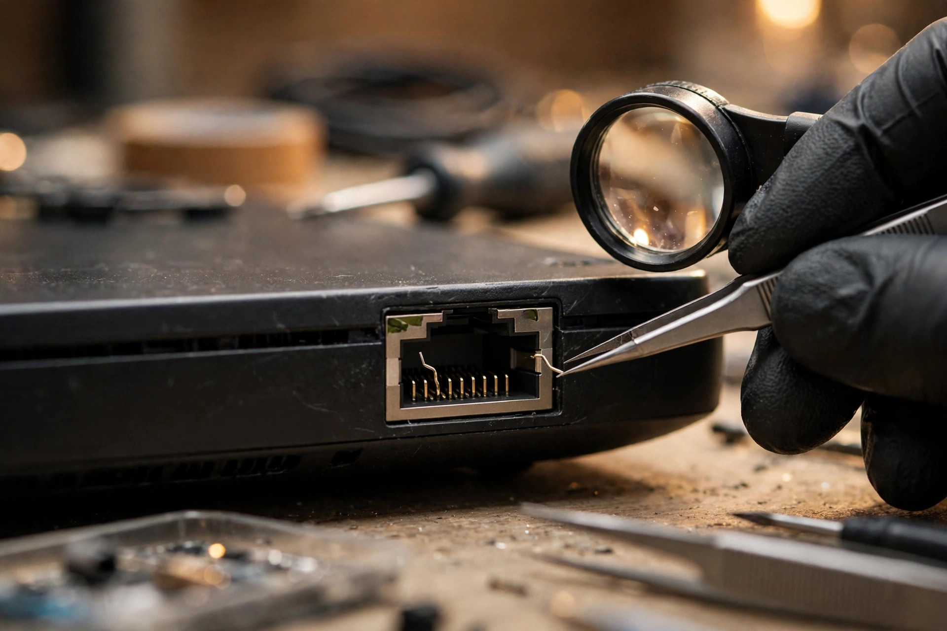
A laptop RJ45 Ethernet port that suddenly cannot get online, drops out intermittently, works only when the cable is held at one angle, or negotiates at only 100 Mbps even though it is connected to Gigabit equipment is usually blamed first on the driver, the router, or the cable, or else written off as a dead motherboard. This guide focuses on one layer only: the physical layer of the RJ45 receptacle on the laptop itself. By physical layer we mean the receptacle structure, the spring contacts, the latch notch, the shield shell, the magnetics, the solder joints and the motherboard traces, and whether any of them is damaged, loose, deformed, oxidised, cracked or blocked by a foreign object. When the physical layer is at fault, no amount of software work will truly fix it. Conversely, when the fault is in the driver, a negotiation setting or the far-end device, replacing the receptacle will not help either. The value of an advanced diagnosis is precisely that it separates the layers before jumping to a conclusion, so that the right part is repaired and the wrong part is not replaced for nothing.
This article has a clear division of labour with an earlier article. The earlier article, laptop-ethernet-port-not-working-advanced-hk, is a functional disconnection article: its focus is why a connection cannot be established or keeps dropping, covering drivers, settings, routers, cables and negotiation. This article is a physical-failure special: its focus is whether the port itself is already broken, which part is broken, how to prove that it is that part, and whether to repair it, replace it or work around it with an adapter. Functional checks appear here only as comparison steps inside the layered elimination procedure, not as the main body. If you have not yet done the most basic elimination, such as trying another known-good cable, trying another far-end port and restarting the computer, do that first, and then use the layered method in this guide to narrow the fault down.
Every operation in this guide that involves opening the machine, measuring, re-soldering, replacing a receptacle, or inspecting motherboard solder joints and traces is inspection work for a professional. Readers must not attempt those steps themselves. What readers can safely do is limited to visual inspection after shutdown and disconnection, swapping cables, swapping far-end ports for cross-testing, checking the negotiated speed shown by the system, and backing up data. If you see scorching, smell burning, see smoke, find a blackened or melted receptacle, or find a plug that is abnormally hot, stop using that port immediately, do not insert any further cable, and do not repeatedly plug and unplug to test it. If liquid ingress is suspected, disconnect power first and do not repeatedly power the machine on to test it.
1. A map of the link: seven stages from outside to inside
Before any elimination, you need a map. From the cable to the operating system, a wired link can be divided into seven stages: first, the cable plug; second, the eight spring contacts inside the laptop RJ45 receptacle; third, the receptacle body and shield shell; fourth, the magnetics; fifth, the motherboard traces and solder joints; sixth, the PHY and MAC controller chip; and seventh, the driver and the operating system. A fault at any stage can end up looking like "no network", yet the repair direction is completely different for each stage. The point of layered elimination is to change only one variable at a time, record the result at each stage, and narrow the range step by step, rather than condemning a part on the strength of a single symptom.
The everyday term RJ45 is, strictly speaking, an 8P8C modular interface: eight positions, eight contacts, with four twisted pairs inside. The receptacle is the part on the machine, and the plug is the part on the cable. They are two different parts, and which one is broken must be established separately. A broken plug latch does not mean the receptacle is broken, and a collapsed receptacle spring does not mean the cable is broken. The section on latch failure below returns to this boundary again and again, because confusing the two sides is the most common and most wasteful misdiagnosis in this area.
2. Receptacle anatomy: five parts from outside to inside
A laptop RJ45 receptacle can be divided into five parts from outside to inside. Knowing what each part does matters, because two failures with very similar symptoms can point in completely different repair directions: a spring failure and a solder-joint failure can both cause intermittent disconnection, but they are not repaired in the same way.
| Part | Function | Typical appearance when failed |
|---|---|---|
| Plastic body and metal shield shell | Encloses the whole mating assembly, providing mechanical protection, electromagnetic shielding and a grounding path, and is fixed to the motherboard by solder feet | Loose or deformed shell, broken solder feet, so that the whole receptacle moves and the plug insertion depth and angle vary every time |
| Plug guide channel and latch notch | A transverse slot at the bottom of the receptacle into which the plastic latch of the plug springs, locking the plug in place and deciding whether the plug can slide out | Worn rounded slot edge, chipped corner, or a slot blocked by debris, so that the plug goes in but does not lock, and slides out slightly with a light pull |
| Eight spring contacts | Spring metal strips made from a spring alloy such as phosphor bronze, with a gold-plated contact surface, pressed down when the plug is inserted and held against the plug contacts by their own spring force | Loss of spring force, permanent deformation, bending, breakage or oxidation, raising contact resistance and causing intermittent disconnection or speed fallback |
| Indicator LEDs | Usually one at each upper corner of an integrated receptacle, driven by the PHY chip LED pins, reflecting only the link state as judged by the PHY, and carrying no data themselves | LED behaviour inconsistent with actual transmission, or a dead LED, as discussed in the LED trap section |
| Solder tails and magnetics | The receptacle tail connects to the motherboard through solder feet; many laptops use an integrated RJ45 receptacle, commonly called a magjack, in which the transformer, common-mode choke, termination resistor and capacitor network are hidden inside the metal shell of the receptacle before the signal reaches the PHY chip | Cracked solder joints, or open or shorted magnetics, which can look completely normal from outside while the link behaves abnormally |
3. Pin assignment: why "works, but only at 100 Mbps" is a physical-layer clue
Pin assignment is the foundation of the whole physical diagnosis. The table below gives the T568A and T568B colour orders side by side. The two standards differ only in that the orange and green pairs are swapped, their electrical performance is the same, and both ends of a straight-through cable must use the same standard.
| Pin | T568B colour | T568A colour | 10 / 100 use | Gigabit use |
|---|---|---|---|---|
| 1 | White-orange | White-green | Transmit | Bidirectional data BI_DA |
| 2 | Orange | Green | Transmit | Bidirectional data BI_DA |
| 3 | White-green | White-orange | Receive | Bidirectional data BI_DB |
| 4 | Blue | Blue | Not used for data | Bidirectional data BI_DC |
| 5 | White-blue | White-blue | Not used for data | Bidirectional data BI_DC |
| 6 | Green | Orange | Receive | Bidirectional data BI_DB |
| 7 | White-brown | White-brown | Not used for data | Bidirectional data BI_DD |
| 8 | Brown | Brown | Not used for data | Bidirectional data BI_DD |
So "still connected, but only at 100 Mbps" is itself a physical-layer clue: one pair may be faulty, causing negotiation to fall back to 100 Mbps. But it is only a clue, not a conviction. A far-end device that only supports 100 Mbps, a setting forced to a fixed speed, an inadequate cable category, or an adapter that itself only supports 100 Mbps can produce exactly the same 100 Mbps result. Cross-testing is required to exclude those causes before the suspicion can be narrowed to the physical layer. The trap in the opposite direction must also be remembered: "it gets online" does not mean the receptacle is healthy. If pins 4 to 5 or 7 to 8 are broken, 10 and 100 Mbps operation continues normally, and the fault can stay hidden for a long time until Gigabit operation is needed one day. A claim of "it works" without a comparison of the negotiated speed is not evidence.
4. Why ports fail: eight physical failure mechanisms
The eight mechanisms below are each described in terms of mechanism, typical symptoms and a first way to distinguish them. Do not read them as a mere list of names. In real machines these mechanisms rarely appear alone. A common combination is long-term sideways pulling that wears the latch notch, so that the plug shifts, the springs take uneven force, one pin makes poor contact and negotiation falls back, while the solder joints crack under the same leverage at the same time. One symptom can therefore have several layers damaged at once, and the purpose of layered elimination is to narrow the range, not to convict on a single test.
Mechanism 1: Insertion fatigue and spring elastic fatigue
The eight contacts inside the receptacle are essentially springs. Every insertion presses them down and lets them spring back; repeated insertion, crooked insertion and sideways removal all reduce spring force, a process called stress relaxation or elastic fatigue. Connector product specifications can be used as a reference scale, but with an explicit qualification: individual connector products are specified with a minimum insertion life of 750 cycles, a contact resistance limit of 20 milliohms and a contact gold plating thickness of 1.27 micrometres, and those numbers are the specifications of individual connector products, not a guaranteed value for a laptop receptacle, because different models use different materials, so 750 cycles must not be written as a laptop guarantee. A commuting pattern of several insertions a day accumulates a substantial count over a few years, and exceeding that kind of reference scale is not surprising. The consequence of falling spring force is not an instant break, but falling contact pressure, rising contact resistance and greater sensitivity to vibration, temperature and oxidation. The early sign is intermittent disconnection that appears when the cable is touched, and only later does it become a permanent speed fallback or no link at all. That gradual progression is the biggest difference between a physical failure and a driver problem: a driver problem usually either works or does not work, and does not behave as "it works only while held". The way to distinguish spring fatigue is visual inspection after shutdown and disconnection, plus cross-testing with another known-good cable. Spring deformation typically shows the pattern "the same with a different cable, normal on a different machine", and the symptoms are strongly related to plug position and angle.
Mechanism 2: Bent, collapsed and broken pins
Bending is caused by crooked insertion, forced pushing, or burrs on the plug contacts pushing an individual spring out of line. A bent pin may touch a neighbouring pin and cause a short circuit, or may fail to touch the plug contact and cause an open circuit. Collapse happens when a spring is pressed beyond its elastic limit and permanently deforms, so that it does not return to its original position, and that pin looks visibly lower than its neighbours. Breakage happens when the root of a spring fractures from metal fatigue, or is torn off by external force, and the broken pin usually retreats deep inside the receptacle, where it may not be immediately visible to the naked eye, and must be checked with a magnifier and a torch held at an angle, comparing the height of all eight pins for consistency. Typical symptoms are a connection that works only at one angle, a link that drops when the cable is lightly touched, a fall from Gigabit to 100 Mbps, and an individual pin that is visibly lower than the others, bent, or chipped. Inspection is limited to looking. Never use a metal pin to pry or straighten a contact, because a bent pin is easily turned into a broken pin, and a repairable fault is easily turned into a receptacle replacement. That is a hard rule, and this guide gives no instruction for straightening pins with a metal tool.
Mechanism 3: Pin oxidation and corrosion
Copper exposed to oxygen and moisture forms oxides, and high humidity, salt and sulphur-bearing pollutants accelerate the process. The products conduct far worse than pure metal, forming a thin insulating layer on the contact surface and raising contact resistance. The gold plating layer is itself a barrier, but once the plating is worn, has pinholes, or exposes the underlying metal at its edges, corrosion has an entry point. The gold layer is very thin and contains microscopic pores, through which moisture and sulphur-bearing gases can penetrate to attack the nickel layer and the copper base beneath, producing sulphide corrosion products that spread from the pores to the surface and raise contact resistance. Fretting wear is part of the same chain: extremely small relative movement between plug and receptacle, from vibration, thermal expansion and contraction, or moving the cable, wears away the gold layer, exposes the underlying metal to oxidation again, and lets oxide debris accumulate on the contact surface, forming a cycle of wear, oxidation and rising resistance. Typical symptoms are instability on first use after a long period of disuse in a damp environment, intermittent behaviour, and pins that look dull, blackened, greenish, or covered with powdery deposits, although colour is only a reference and must never be used alone to convict. In terms of distinction, oxidation usually affects a whole group of pins or several pins at once, rather than a single broken pin, and after cable and port cross-testing the fault remains concentrated on the same port of the same machine. Do not instruct readers to scrape pins with a metal tool or to pour an unknown cleaning agent into the receptacle. The correct statement is that suspected oxidation is an inspection item for professional handling, because scraping by hand can wear through the remaining plating and bend the springs, turning a repairable fault into an unrepairable one. Pouring alcohol or contact cleaner into the receptacle can dissolve plastic, leave conductive residue, or accelerate corrosion, and cleaning should only be judged by the inspection side according to the receptacle material, never by pouring liquid in at home.
Mechanism 4: Latch failure, distinguishing the plug latch from the receptacle latch notch
The top of the plug carries a flexible plastic latch tab. On insertion the tab passes over a ridge inside the receptacle wall and springs up, locking the plug so that it cannot be pulled out. Latch failure has two different locations, and they must be kept separate, or readers will be misled into replacing the wrong part. First, plug latch breakage or loss of elasticity: plastic ages and hardens, hard pulling breaks it, and pulling hard while the latch has not been fully pressed down because the boot is in the way can also snap it. The result is a plug that does not sit firmly, slides out with a light pull, and makes intermittent contact as the plug shifts. Second, receptacle latch notch wear, deformation or bent metal parts: once the ridge or metal structure inside the receptacle that holds the latch is deformed, even a brand-new cable gives no click and does not lock firmly. Typical symptoms are the absence of a click, a cable that slides out easily, and a link that drops when the cable body is moved. The key distinction is to test first with a known-good cable. If a replacement cable locks firmly, the problem is in the old plug latch. If several good cables all fail to lock, the problem points to the laptop receptacle side. Do not write "replace the motherboard" as soon as a plug fails to lock. A broken plug latch does not mean the laptop port is broken, and fixing a plug with glue, paper packing or tying is not recommended as a long-term practice, because it can keep the plug under sideways force and accelerate damage to the receptacle springs and latch notch. A plug that does not lock is not a minor issue but the start of a whole failure chain: poor locking lets the plug shift slightly, slight movement accelerates fretting wear, contact resistance rises, intermittent disconnection follows, and the user presses harder and plugs and unplugs more often, putting even greater force on the springs and solder joints.
Mechanism 5: Magnetics failure
An integrated receptacle contains a small toroidal transformer, a common-mode choke, termination resistors and capacitors, ten or more components in total. The magnetics provide electrical isolation, meaning isolation between the PHY side and the line side that must meet the isolation requirements of IEEE 802.3, together with common-mode noise suppression and impedance matching. Failure routes include winding open circuits, winding short circuits, shorted turns, burnt termination resistors, surge or electrostatic damage, and characteristic drift from long-term heat. Non-standard passive power injection that puts a direct voltage directly onto a pair can damage termination resistors, but that practice is different from standard negotiated power delivery and must not be confused with it. A shorted turn is the most insidious case: a few turns shorted together within the same winding may change the direct-current resistance only slightly, so that an ordinary measurement may not detect it, while the inductance deviates clearly from the normal ratio and high-speed signals still attenuate with a high error rate. Typical symptoms are a completely normal appearance with no link, a link that repeatedly establishes and drops, low-speed-only operation, or a high packet-loss rate, sometimes with LED behaviour inconsistent with the system state. This layer cannot be determined by looking alone. The clues are that appearance, springs, solder joints, cable, far-end port and driver have all been cross-checked, the same port is still at fault, and replacing the receptacle or module restores operation. Final confirmation is motherboard-level inspection work, checked against the circuit diagram and component part number for that machine, and readers must not be taught to measure and then judge for themselves which component has burnt out, because the pin layout and internal configuration of integrated receptacles can differ completely between models, and the same appearance does not mean the same internal wiring. The red line is that magnetics failure must not be written as necessarily caused by lightning or by power injection: a surge is only one possible cause, and the wording must be that the cause requires inspection to confirm. Magnetics failure usually kills a whole pair rather than all pairs of a receptacle at once, so if all eight pins are dead and all LEDs are dark, the PHY, the power supply and the motherboard traces must be suspected at the same time, not the magnetics alone.
Mechanism 6: Solder-joint cracking and cold joints
A cold or dry solder joint means that the solder did not fully melt and flow during soldering, so that the bond between the joint and the pad or pin is weak, and the surface can look dull, rough, cracked, or full of voids. Even if such a joint passed testing at the factory, long-term thermal expansion and contraction, vibration and mechanical stress transmitted by insertion and removal can widen micro-cracks until they become intermittent open circuits or complete open circuits. Laptop receptacles are mostly surface-mounted on the motherboard, and their solder joints are responsible for both electrical connection and mechanical fixing, so insertion force, cable pulling force and chassis bending force are all transmitted through the receptacle body to the joints, making receptacle joints a high-risk location. The general mechanisms of solder-joint failure include mechanical fatigue, where repeated small stresses create micro-cracks that slowly expand; thermal fatigue, where different thermal expansion coefficients of solder, circuit board and components create shear stress at the joint interface during power-on and load-change thermal cycles; and single overload, where a hard cable pull or a drop cracks a joint immediately or lifts a pad. A lifted pad is more serious than a cracked joint, because the copper foil of the motherboard is torn away as well, greatly increasing repair difficulty and risk. The most typical symptom is the classic intermittent pattern: pressing near the receptacle, moving the chassis, or a difference between cold and hot machine states all change the result, and sometimes light pressure on the motherboard receptacle area briefly restores the link. In terms of distinction, cracks or dull joints are sometimes visible, but micro-cracks may not be visible to the naked eye. Readers must not be taught to reflow a joint themselves with a hot-air tool, because heating curves, temperatures and the risk to neighbouring components are professional repair matters, and this guide only states that a suspected solder-joint problem is a disassembly inspection item.
Mechanism 7: Loose or deformed shield shell
The metal shield shell around an RJ45 receptacle provides electromagnetic shielding, mechanical fixing and grounding at the same time. A loose shell, broken solder feet, or a dented shell lets the whole receptacle move on the motherboard: the plug insertion depth and angle differ every time, spring contact pressure becomes unstable, and shielding and grounding integrity fall, reducing interference immunity. Typical symptoms are an obvious looseness of the receptacle itself, a whole port that moves after the plug is inserted, and symptoms that vary greatly with plug angle. The point of distinction is that the whole receptacle moves, rather than a single pin being at fault. Checking the shell for deformation or looseness by eye is a distinction that can already be made at the first layer. A loose shield shell is also often assessed together with solder-joint problems, because a loose shell and stressed joints often appear at the same time, and fixing only one direction may not solve the whole problem.
Mechanism 8: Foreign objects, liquid and physical impact
Need a laptop repair expert?
Free diagnosis · Transparent pricing · No fix, no fee · 180-day warranty
Dust, paper scraps and food crumbs stuck inside a receptacle prevent the plug from going fully in, or prevent individual pins from making contact. Liquid, such as a spilled drink, rainwater or condensation, can cause short circuits and corrosion, and residue left after the liquid dries continues to affect contact. A laptop dropped on the floor, squeezed in a backpack, or dragged by its cable can crack the receptacle shell, deform the shield, and stress the solder feet. Typical symptoms are a sudden onset, where operation was normal before and fails after a particular event; a plug that does not go fully in, or sits higher on one side than the other; visible debris; or a history of liquid ingress. The handling principles must be stated: if liquid ingress is suspected, disconnect power first, do not repeatedly power on to test, and do not pick at debris with a metal tool while power is connected. Pins on a line carrying power can be live in some circumstances, and a metal tool bridging contacts carries a short-circuit risk. Removing debris and post-liquid inspection are inspection items. When checking, first look for cracks, deformation or scorch marks on the shell, and do not simply blame the driver. Inspection is limited to visual checking after shutdown and disconnection, and compressed air must not be blasted at close range, because it can push debris deeper, nor must liquid cleaner be poured into the receptacle.
5. Four-layer distinction: which layer is at fault
After the eight mechanisms, readers need a distinction table that maps symptoms to a suspected layer. The table below is one of the core tables of this guide, and its layer count must be correct: physical contact layer, magnetics layer, trace and solder-joint layer, and PHY and driver system layer, four layers in total.
| Suspected layer | Common clues | Phenomena seen | First distinction steps, without disassembly |
|---|---|---|---|
| Physical contact layer, including springs, latch, foreign objects and oxidation | Angle sensitivity, works only when held, does not lock, changes when the cable is changed | Intermittent disconnection, speed fallback, drops when the cable is moved | Visual inspection, a known-good cable, a different far-end port, and a record of which action makes the symptom appear or disappear |
| Magnetics layer | Normal appearance but abnormal link, no improvement after changing cable and far-end port | No link, repeated negotiation failure, low speed only | After the contact layer and cable layer are excluded, the fault is still concentrated on the same port; final confirmation requires motherboard-level inspection |
| Trace and solder-joint layer | Changes when the receptacle area is pressed, differences between cold and hot machine states, a whole receptacle that is loose | Intermittent open circuit, works sometimes and not others, related to force on the chassis | Record the relationship between pressing, temperature and vibration and the symptom; do not heat or pry solder joints yourself |
| PHY and driver system layer | Whether the device appears in Device Manager, driver state, negotiation settings | Device disappears, driver error, forced fixed speed, power-saving settings putting the link to sleep | Check whether the device appears, whether the driver and the speed and duplex setting are set to auto-negotiation, and compare with another machine on the same far-end port |
6. LED traps: useful, but never read the LEDs alone
The general principle, subject to the manufacturer documentation for the machine, is that the PHY outputs link and activity indication through LED pins. A common division of labour is that one LED shows link establishment and activity, meaning steady light means a link is established, flashing means traffic, and dark means no link, while the other LED shows negotiated speed, for example with different colours or on and off states corresponding to 10, 100 and 1000 Mbps. The official Intel documentation for the I210-T1 is an example of this division: the link and activity LED dark means no link, steady means a link, and flashing means activity, while the speed LED dark means 10 Mbps, green means 100 Mbps, and amber means 1 Gbps. The Intel DH61WW motherboard specification has a similar speed LED definition, but other manufacturers and other models can be completely different, with some using green for Gigabit and amber for fallback.
Three traps of reading LEDs alone must be stated together. First, LED definitions vary by manufacturer, chip and model, and the same colour can mean a different speed on different machines; on some machines the LED function is set by PHY registers and can be redefined. This guide therefore makes no universal claim such as green always means Gigabit, and always states that the machine manual or manufacturer documentation is authoritative. Second, a lit LED does not mean the physical layer is healthy: the LED only reflects that the PHY considers a link established, and says nothing about error rate, the margin of individual pairs, or drift in magnetics characteristics. A link that is lit but fallen back in speed or intermittently dropping can still be a physical-layer problem. Third, a dark LED does not mean the receptacle is broken: it can be a far-end port switched off, an open cable, a PHY without power, or a driver or power-saving setting problem. A dark LED is a starting point, not a conclusion. One supplementary point also applies: the LED itself can burn out or its solder feet can break, so that the LED stays dark while the network works normally, which means dark does not equal no network, and lit does not equal healthy transmission. The correct method is to read the LED, the negotiated speed shown by the system, and the cross-test results together. For example, a lit LED, a system speed of 100 Mbps, and the same 100 Mbps after changing cable and far-end port strengthen the physical-layer clue, while a dark LED, a system message that the network cable is unplugged, and the same result after changing cable and far-end port point next to the PHY and driver layer.
7. Five-layer elimination: do not change the order
The principle is to start with steps that do not require disassembly, cost the least, and are reversible; write down the result after each layer, and do not change all variables at once, or you will never know which change was the real cause. Change only one variable at a time, and record negotiated speed, LED state and stability each time. The five layers below are the appearance and mechanical layer, the contact and cable cross-testing layer, the magnetics and LED reading layer, the solder-joint and trace layer, and the PHY and driver system confirmation layer.
Layer 1: Appearance and mechanical
After shutdown and disconnection of power and cables, inspect without using a metal tool inside a powered receptacle. Look for whether any of the eight pins is bent, broken, visibly collapsed or discoloured; whether the latch notch is deformed; whether the shield shell is loose or dented; whether there is debris inside the receptacle; and whether the plug gives a click on insertion and shows obvious wobble once fully inserted. Record the relationship between symptoms and actions: which angle works and which angle fails, and whether holding the plug works while releasing it fails. For a folding receptacle, also check whether the hinge is loose and whether the opened receptacle sits crooked, and do not judge a folding receptacle by the feel of a standard receptacle.
Layer 2: Contact and cable cross-testing
Test with a known-good cable, meaning the same cable has first been verified as normal on another machine with the same far-end port, and do not substitute "newly bought" for "verified". Cross-test four combinations: original cable with original far-end port, good cable with original far-end port, original cable with another far-end port, and good cable with another far-end port. Each time record whether there is a link, the negotiated speed, the LED state, and how long the link lasts. Plug latch checking also belongs in this layer: if a replacement cable locks firmly, the problem is in the plug; if several good cables all fail to lock, the problem points to the receptacle side. Cable category is only background: Category 5e or above is generally required for Gigabit operation, but a cable printed as Category 6 does not guarantee that all four internal pairs are intact, so fallback testing is still required. Cross-testing must compare negotiated speed, not merely whether the machine gets online, because 100 Mbps operation uses only two pairs and can hide a fault in the other two pairs.
Layer 3: Magnetics and LED reading
On the basis of the Layer 2 results, read the LEDs together with the system negotiated speed, and compare them with the LED definition in the machine manual. The key question is whether appearance is normal and changing cable and far-end port brings no improvement while the link remains abnormal, in which case suspicion of the magnetics layer rises. The conclusion at this layer can only be written as suspected magnetics layer, requiring motherboard-level inspection to confirm, and must not be written as a diagnosis. A useful comparison at this layer is that an external adapter works completely normally online, while the built-in port fails under every cable, far-end port and system condition, which strongly points to the built-in port chain rather than the system or the network, but still does not separate receptacle, magnetics, trace and PHY, which must be narrowed further in Layer 4 and Layer 5.
Layer 4: Solder joints and traces
Record the relationship between pressing, temperature and vibration and the symptom: for example, light pressure near the receptacle changing the symptom, normal operation when cold and failure when hot, or a link that drops when the chassis is moved, all point to the solder-joint or trace layer. A loose shield shell is also assessed in this layer, because a loose shell and stressed joints often appear together. In principle this layer already requires disassembly inspection, and this guide only lists it as an inspection item, giving no step-by-step disassembly, heating or re-soldering instruction. The reason is that receptacle fixing methods, motherboard layouts and the heat tolerance of neighbouring components differ between models, and a generic instruction would mislead. Readers who suspect a solder-joint problem should record the pressing, temperature and symptom relationship and hand it to the inspection side for reference, rather than heating or prying joints themselves.
Layer 5: PHY and driver system confirmation
Confirm whether the device itself appears, for example the Ethernet controller in Device Manager or system information, its driver state, and whether speed and duplex are set to auto-negotiation. Do not teach readers to force 1 Gbps on one side only, because one-sided forcing can cause a negotiation mismatch. For comparison testing, if another machine is normal on the same cable and the same far-end port, the evidence for a laptop-side problem is strengthened; if another machine shows the same abnormality, first suspect the cable, the far-end port, or the setting. After excluding power-saving or power management putting the PHY to sleep and driver abnormalities after a system update, if the fault is still concentrated on the same port, suspicion can be narrowed to the PHY chip itself or its power supply, clock and other motherboard-level issues, which are likewise in the scope of inspection confirmation, and must not be written directly from system state as a burnt PHY. Only when this layer is complete is the five-layer elimination finished, and skipping any earlier layer leaves a gap in the conclusion.
8. Hong Kong conditions: why failures are especially likely here
Hong Kong conditions must be written realistically, not as a generic article. First, humidity and oxidation. The high-humidity environment of Hong Kong raises the risk of contact oxidation and corrosion compared with drier regions, especially for machines kept near windows, under air-conditioner outlets where condensation forms, or in damp rooms. A rarely used port is more likely to develop a film on its surface that affects contact, and a port left unplugged for months and then used for the first time is more likely to fail, because without insertion friction to wear the surface film away, the oxide layer can accumulate quietly. Alternating air-conditioning on and off makes condensation inside the receptacle likely, and moisture plus sulphur-bearing air plus pores in the gold plating is exactly the breeding ground for pore corrosion. Prevention is to keep the storage environment dry, not to leave a plug inserted under force for a long time, to inspect regularly rather than to run powered tests regularly, and not to clean with unknown liquids.
Second, commuting insertion and removal. Carrying a machine to work or school every day and plugging and unplugging at different locations raises both the insertion count and the chance of sideways force. A cable squeezed inside a backpack, a lid closed while the cable is still plugged in, or a machine put into a bag with the cable attached all transmit force to the receptacle and solder joints. A pattern of plugging in at the office and at home every day makes the clock for spring fatigue and solder-joint stress run faster. Prevention is to press the latch before removing a plug, to insert and remove straight, never to pull hard on the cable body, to remove the cable before packing the machine, and never to close the lid and carry the machine with the cable still plugged in.
Third, dock and adapter abuse. A dock or a USB or Thunderbolt adapter is not a repair of the original port. Using an adapter as a permanent substitute, letting an adapter hang in the air so that the port takes its weight, or letting an adapter cable bend long-term against a desk edge can turn a temporary substitute into a second stress point. A dock left permanently plugged in turns the plug into a lever: a small movement of the desk or a tug on the dock cable transmits the whole moment to the laptop receptacle. An even more common pattern is using a plugged-in adapter as a fixed station, where the adapter itself is heavy and its cable is thick, and the long-term sideways force falls first on the receptacle shell and solder joints. The correct habit for a fixed station using a dock is to keep the cable run straight and free of hanging force, and to remove the cable before moving the machine rather than dragging the machine by its cable. In addition, some adapters only support 100 Mbps or are limited by USB bandwidth and drivers, so their speed performance cannot be compared directly with an original Gigabit port, and before buying an adapter, its stated supported speed and system requirements must be checked rather than assuming that every adapter equals an original Gigabit port.
Fourth, a reminder about thin machines and folding interfaces. Some ultra-thin models use a folding or drop-down RJ45 receptacle or require a dedicated adapter cable, with a structure different from a standard receptacle, so the machine manual must be checked first to confirm the interface form, and the inspection method for a standard receptacle must not be applied directly. Fifth, local parts and pricing reality. The part number, pin layout, height and shield structure of an RJ45 receptacle and an integrated magnetics module vary by model, and are not a single universal part that fits every machine. Some models require a whole input and output small board to be replaced together, some require only the receptacle to be replaced, and some manufacturer routes replace only the motherboard. Motherboard-level repair also requires the traces, pads and neighbouring components to be confirmed first. All prices are subject to a written quotation after inspection, this guide gives no specific repair price, and estimating a price from a model number in advance is easily wrong, because only after opening the machine is it known whether the fault is in the receptacle, the solder joints, the magnetics or the PHY.
9. Common misdiagnoses and traps
The eight misdiagnoses below should each be named, so that readers can check whether they have fallen into any of them. First, misjudging a driver, router or cable problem: reinstalling drivers, resetting the router and replacing a whole set of equipment without cross-testing, with the original port problem still present. The correct order is cross-testing first, then settings. Second, treating "it works after changing the cable" as "it is fixed": after a cable change the link may be normal only because the new plug latch is tighter and temporarily holds a deformed receptacle spring in place, while the root cause on the receptacle side is unresolved and will reappear later. Readers should observe for a period of time and record how long the negotiated speed and stability last after a cable change, rather than closing the case on one test. Third, misreading by LEDs alone: a lit LED does not mean healthy, and a dark LED does not mean a broken receptacle, as detailed in the LED trap section. Fourth, mistaking a USB adapter for a repair of the original port: an adapter bypasses the original port, it does not repair it. Physical damage to the original port, such as a loose shield shell or cracked solder joints, remains, and the adapter has its own speed limit, driver and power limits that cannot be compared directly. Fifth, mistaking speed fallback for a network provider problem: negotiated speed is the result of negotiation between the two ends of the local link, so fallback points first to the local physical layer and settings, and must not be blamed on an external network before local cross-testing. Sixth, mistaking a plug latch problem for a laptop port problem: cable replacement testing is the dividing line, as detailed in the latch failure section. Seventh, turning self-cleaning into secondary damage: picking with a metal pin, scraping with a hard object, pouring liquid in, or blowing solder joints with hot air can deform springs, wear through plating, cause short circuits, or damage neighbouring components. This guide only recommends visual inspection after shutdown and cross-testing, and gives no invasive self-repair steps. Eighth, convicting on a single symptom: for example, 100 Mbps can be caused by pair damage, a far-end device limit, a fixed-speed setting, or an adapter limit, among other causes, and cross-testing is required to narrow it down rather than writing a conclusion from one number. Two related traps, not numbered within the eight above, should also be guarded against: "it gets online" does not mean the receptacle is healthy, because 10 and 100 Mbps operation uses only two pairs, and "reinstalling the driver did not help" does not mean the hardware is broken, because a failed driver reinstall only excludes the driver layer, while the hardware layer still contains cable, receptacle, magnetics, solder joints, traces and PHY possibilities, and must not jump directly to motherboard replacement.
10. Repair, replacement and upgrade decision framework
The decision table must not be written as always recommending replacement or always recommending an adapter, but must be divided by inspection result. All prices are subject to a written quotation after inspection.
| Situation | More reasonable direction | Trade-offs to state |
|---|---|---|
| Problem confirmed in the plug latch or cable | Replace the cable or re-terminate the plug, depending on cable condition | Lowest cost; but confirm the new cable has been verified as normal, and do not draw a conclusion from an unverified new cable |
| Problem confirmed in receptacle springs, latch notch or shield shell, with no further damage seen to magnetics or pads | Replace the receptacle alone, whether an independent receptacle or an integrated receptacle depending on model | Disassembly repair; the part number must correspond to the model, it is not a universal part; all prices are subject to a written quotation after inspection |
| Problem points to the magnetics layer or the solder-joint and trace layer | Motherboard-level repair assessment, including replacing an integrated receptacle, handling solder joints and checking traces | Repairability must be judged by circuit and component condition; if pads or traces are already damaged, the repair scope and difficulty rise, and the inspection result is authoritative |
| Original port damage is extensive, repair value is doubtful, or the user needs immediate online access | A USB or Thunderbolt adapter as a substitute | Advantages are immediate use and no disassembly; disadvantages are that it does not repair the original port, speed and stability are affected by adapter specification, interface bandwidth and drivers, and long-term hanging force can become a new damage point; when buying, compare the stated supported speed and system requirements of the adapter |
| Several layers damaged at once, for example a loose receptacle plus cracked solder joints plus magnetics abnormality, or other parts of the motherboard also faulty | Make a comprehensive judgement from the whole-machine inspection result | Do not piece together separate quotations item by item; all prices are subject to a written quotation after inspection, and the user then decides whether to repair, replace or use a substitute |
| The machine itself has reached its replacement cycle, or other ageing problems remain after repair | Compare repair and replacement together | The basis of comparison should be the inspection result and the written quotation, not a single symptom; this guide gives no replacement model recommendation |
Four questions for readers at decision time can serve as a closing checklist. First, has cross-testing already proved that the problem is concentrated on the same port of the laptop. Second, is it damage to a single layer, or damage to several layers at once. Third, does the user want the original port repaired, or immediate online access, because the two answers can differ. Fourth, have the written quotation and repair scope after inspection already been explained clearly before a decision is made.
11. Teaching examples, none of which are real cases
The three examples below are purely teaching illustrations, not real cases, and do not represent any real user or repair record. Example one, not a real case, for teaching illustration only: a laptop used for commuting every day requires its RJ45 cable to be held at one angle before it connects, and two already verified good cables behave the same, while the receptacle latch also fails to lock. Following the five-layer procedure, the cable layer is already excluded, and suspicion points to the receptacle contact layer, including springs and the latch notch, requiring inspection to confirm whether receptacle replacement alone is sufficient or solder joints are also involved. Example two, not a real case, for teaching illustration only: a laptop kept long-term in a damp environment and rarely used on a wired network can only negotiate at 100 Mbps on first use, the same after changing cable and far-end port, with no obvious damage visible. Following the four-layer distinction and the LED section, this combination points to possibilities such as contact-layer oxidation or a magnetics layer that looks normal from outside but is abnormal at the physical layer, requiring inspection to narrow it down, and it must not be written directly as a driver problem or a router problem. Example three, not a real case, for teaching illustration only: a laptop RJ45 port has a whole receptacle that feels loose, and light pressure near the receptacle changes the symptom. That clue points to the shield shell, solder-joint and trace layer, and it is not appropriate to settle the matter by changing the cable alone or using an adapter alone; the repair scope should be decided from the inspection result.
12. Preparing for inspection, and related links
Before inspection, prepare the following information so that the inspection side can narrow the range most quickly: the model and interface form, including whether it is a standard receptacle or a folding receptacle; the way symptoms appear, including which angle works and which angle fails, whether holding works and releasing fails, and whether cold and hot machine states differ; the negotiated speed, including whether the system shows 1 Gbps or 100 Mbps, and the LED state; the cross-testing results already done, including which cables were changed, which far-end ports were changed, and how another machine behaved on the same far-end port; and background such as liquid ingress, a drop, or long-term dock use. This information is not for readers to diagnose by themselves, but to let the inspection side start verification from the suspected layer rather than repeating basic elimination from zero.
For related links, readers can first read pricing and service scope to understand the service framework, with all prices subject to a written quotation after inspection; readers who need to arrange inspection can go to diagnostic booking to understand the inspection arrangements. Disassembly, measurement and soldering are all for professional inspection, and readers only do visual observation and cross-testing. That sentence is the safety line of this guide from start to finish, and it does not change because any section is written in depth.
Shop information is as follows: Room 1209, Daly Plaza, Shek Mun, Shatin, telephone +852 2186 8010, WhatsApp +852 6558 6806, business hours 12:00-19:00. Before seeking help, please complete the non-disassembly parts of the five-layer elimination above, and record negotiated speed, LED state and cross-test results, so that inspection can start directly from verification of the suspected layer rather than repeating basic elimination. What physical failure fears most is not a fault that is total, but a fault that is ambiguous: the LED is lit, the network is online, and the speed has fallen by half, misleading people into thinking that the network is merely slow. Separating which layer is at fault, among pins, springs, latch, magnetics, solder joints and traces, is the first step to repairing the original port properly.
Frequently asked questions
Q1: The cable is plugged in and the machine gets online, but the speed stays at 100 Mbps long-term. Does that mean the receptacle is broken?
A: Not directly. Operation at 100 Mbps uses only pins 1 to 2 and 3 to 6, while Gigabit operation requires all four pairs, so a fault in one pair can cause negotiation to fall back to 100 Mbps, but a far-end device that only supports 100 Mbps, a setting forced to a fixed speed, an inadequate cable category, or an adapter that itself only supports 100 Mbps can produce the same 100 Mbps result. The correct method is to confirm first that the setting is auto-negotiation, then cross-test with a known-good cable and another far-end port, comparing negotiated speed. Only if changing cable and far-end port still gives 100 Mbps should suspicion be narrowed to the laptop physical layer, and inspection should then separate whether the layer is receptacle pins, magnetics, traces or PHY.
Q2: The plug latch is broken. Does that mean the laptop RJ45 port is broken?
A: Not necessarily. The plug latch and the receptacle latch notch are two different locations and must be judged separately. Test first with a known-good cable. If a replacement cable locks firmly, the problem is in the old plug latch, and replacing the cable solves it. If several good cables all fail to lock, the problem points to the laptop receptacle side. A cable with a broken latch must not be held in place long-term with glue, paper packing or tying, because keeping the plug under sideways force can accelerate damage to receptacle springs and the latch notch.
Q3: The receptacle looks completely normal from outside. How can the fault still be at the physical layer?
A: Because magnetics, solder-joint micro-cracks and trace breaks can look completely normal from outside. Magnetics are hidden inside the metal shell of an integrated receptacle, and winding open circuits, short circuits and shorted turns may leave no visible trace. Solder-joint micro-cracks may not be visible to the naked eye, and a trace break is deeper still and mostly invisible to the eye. The clues in these cases are that appearance, springs, cable, far-end port and driver have all been cross-checked, and the same port is still at fault. The conclusion can only be written as suspicion of a particular layer, requiring motherboard-level inspection to confirm, and a normal appearance must not be used to exclude the physical layer.
Q4: A USB or Thunderbolt adapter gets the machine online. Does that mean the original port does not need repair?
A: No. A working adapter only proves that the system and the network are normal, and that the adapter chain itself is normal. It does not prove that the built-in port is healthy, because an adapter bypasses the original port, it does not repair it. Physical damage to the original port, such as a loose shield shell or cracked solder joints, remains. If work depends on the built-in port, for example a fixed station or a dock, an adapter is only a transitional solution. If the machine is near replacement and wired-network demand is low, an adapter can be a reasonable substitute. Which route to choose depends on the inspection result, the written quotation, and how much the user depends on a wired network, with all prices subject to a written quotation after inspection.
Need Professional Laptop Repair?
Laptop King has 15+ years of repair experience in Shek Mun, Sha Tin. Free diagnosis, transparent pricing, no fix no fee. 180-day warranty for your peace of mind.