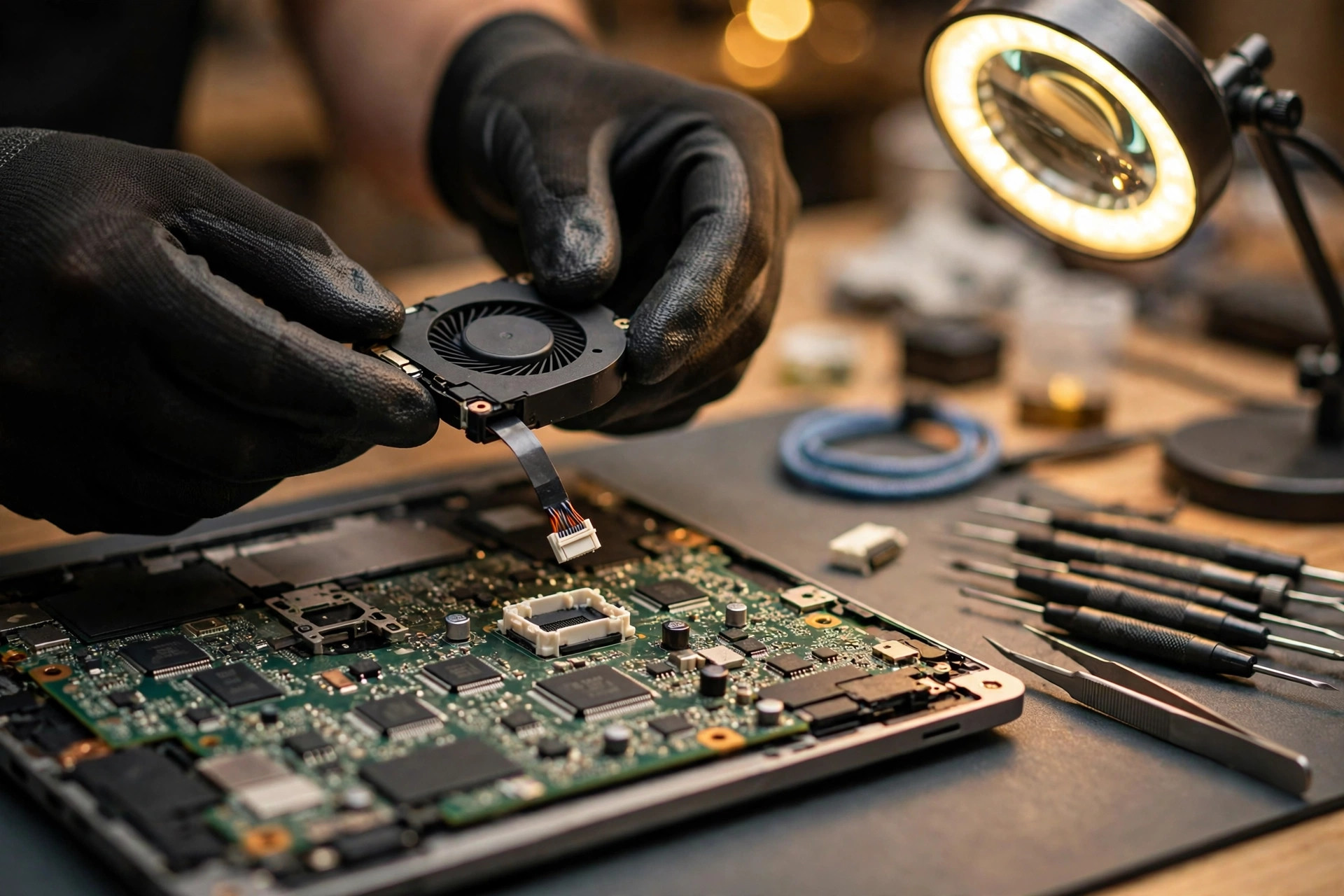
Boundary: this guide covers only the fan speed control layer, not the fan itself
This guide covers only the laptop fan speed control layer, starting from the fan curve command issued by the embedded controller, through pulse width modulation signal generation and duty cycle transmission, through execution by a board-level driver transistor or an in-fan driver integrated circuit, and back through a tachometer feedback signal to the embedded controller, forming a closed loop. This guide does not cover repair details for the fan motor body, bearing condition, blade damage, the temperature sensor body, damage to the embedded controller body itself, or blocked cooling fins, and those directions appear only in a contrast chapter whose purpose is to remind readers that control layer faults and contrast layer faults can look very similar, so sound alone or a speed reading alone cannot directly determine which layer has failed. Readers of this guide only perform external observation and recording, including listening to sound changes, reading speed readings, recording load conditions, recording power modes, recording performance modes, recording when symptoms first appeared and how they change, and this guide never teaches disassembly, never teaches opening the case, never teaches measuring internal circuits, never teaches writing to embedded controller registers, and never teaches replacing internal parts, because every internal inspection involving opening the case, measuring, replacing parts, or writing firmware settings must be left to professional inspection. For any specific laptop brand or model, the embedded controller model, pulse width modulation frequency, pin arrangement, fan supply voltage, minimum speed, curve thresholds, and fan-stop temperature are all written as varying by model until supported by that model's original service manual, and no numbers are added in this guide to fill those gaps. Numbers from the desktop fan specification are quoted only after stating the nature of their source, in order to explain mechanisms, and they are never applied directly to a laptop flex cable or a laptop fan. On charges, apart from four confirmed reference prices that are explicitly listed later in this guide, everything else is subject to a written quotation after inspection, and those four prices do not represent the fee for this topic; they are included only to show that different repair directions have completely different price starting points, and readers must not treat them as a quotation for this topic.
Chapter 1: A map of the control layer, six layers first, not four things described as one
The fan speed control layer can be divided into six layers, and each layer has its own input, output, and failure mode, so describing them together produces the familiar situation in which replacing the fan does not fix the problem and repairing the board does not fix the problem either. Layer zero is the embedded controller decision layer, which reads temperature inputs, consults a built-in fan curve or temperature-to-speed table, and sets a target duty cycle, while that decision is also affected by basic input output system settings, manufacturer control modes, and whether the machine is on AC power or battery power, and the curve values vary by model and cannot be found in public sources. Layer one is the pulse width modulation generation and output layer, in which a timer inside the embedded controller, a super input output chip, or a hardware monitoring chip generates a square wave, which is then output through an open-drain buffer or a transistor, and that output is a logic signal rather than motor power, so it cannot drive a motor by itself. Layer two is the driver layer, which takes two architectures that must never be confused: a board-level driver uses a metal oxide semiconductor field effect transistor or a transistor on the board as a switch for motor power, while an in-fan driver uses a brushless direct current motor driver integrated circuit inside the fan, which receives the logic command and performs commutation and power switching itself, and the failure points of the two architectures are completely different. Layer three is the fan execution layer, in which a brushless direct current motor turns and drives a blower impeller to produce airflow, and this layer appears in this guide only as the terminal of the control layer, while motor body problems belong to the contrast layer and are not developed here. Layer four is the tachometer feedback generation layer, in which the fan internally outputs a speed pulse signal, and that signal is not power, because its only purpose is to report actual speed. Layer five is the feedback transmission and counting layer, in which the embedded controller or monitoring chip counts pulses, converts them into revolutions per minute, compares the result with the target, and corrects the next duty cycle, and the closed loop proceeds in circles in exactly this way. The key distinction must be remembered: whether the embedded controller has issued a pulse width modulation signal and whether the fan has understood that signal are two independent questions, and whether the fan is spinning and whether the embedded controller has received tachometer feedback are also two independent questions. The four combinations can fail independently, so replacing the fan does not necessarily fix an embedded controller or driver layer problem, and repairing the board does not necessarily fix an in-fan driver problem. When readers record symptoms, they should record sound, readings, load, and mode together, because if any one of the four is missing, professional inspectors will have to ask again from the beginning.
| Layer | Task | Output | What readers see when it fails |
|---|---|---|---|
| Layer zero, embedded controller decision | Read temperature, consult curve, set target duty cycle | Target duty cycle | Full speed at light load, or no acceleration at heavy load, speed decoupled from load |
| Layer one, signal generation and output | Timer generates square wave, open-drain output | Pulse width modulation square wave | Stuck at full speed, or completely unresponsive to load, or intermittent speed changes |
| Layer two, driver | Board switch or in-fan driver executes command | Motor coil current | Uncontrolled near-full speed, or no spin, or intermittent stopping |
| Layer three, fan execution | Motor drives impeller to produce airflow | Airflow | Speed cannot rise, or abnormal noise, contrast layer |
| Layer four, feedback generation | Fan internally outputs speed pulses | Tachometer pulse signal | Fan clearly spinning but reading shows zero or frozen |
| Layer five, feedback counting and closed loop | Count pulses, convert to speed, correct duty cycle | Corrected duty cycle | Reading jumps, or reads about half or double the real speed |
Chapter 2: Embedded controller curve commands, lookup tables first, not immediate linear response
The essence of an embedded controller curve command is a table, not a slogan. Each row of the table maps one temperature interval to one target speed or target duty cycle, and after the embedded controller reads a temperature, it finds the interval that applies, sets the target duty cycle, and then applies closed-loop correction before the fan reaches the corresponding speed. The division of temperature intervals, the target value of each interval, the slope between intervals, and whether there is hysteresis or smoothing when jumping from a low interval to a high interval are all private firmware settings of the original manufacturer, and no specific values can be found in public sources, so they vary by model. In external observation, readers should not expect to memorise a universal curve, and they should not treat observations from one machine as a standard for another machine. The correct recording method is to record, on the same machine, how fan sound changes from quiet to loud and how monitoring tool readings change across four conditions, namely idle, light load, medium load, and heavy load, together with the power mode and performance mode settings, repeated several times, in order to see whether the pattern reproduces stably or changes every time. A stably reproducing step jump is likely to be an interval characteristic of the curve itself, while random jumping every time is worth suspecting at the driver layer or the feedback layer. Curves are also affected by modes, because performance mode, balanced mode, quiet mode, and power saving mode can correspond to different curve tables, and AC power mode and battery mode can also correspond to different curve tables, so the mode in effect must be written down when recording, otherwise professional inspectors may think the curve is wrong when only the mode is different. Fan mode options provided by the basic input output system or a manufacturer control centre, where that model provides them, only change the curve or mode selection at layer zero, and they cannot repair hardware problems at layer one, layer two, or layer five, so temporary improvement after changing modes does not mean the fault has disappeared, and pushing the mode toward full speed must not be treated as a repair, because full speed mode can only serve as temporary observation and cannot count as a repair. Two control programs fighting each other is also a common layer zero problem, because an embedded controller or basic input output system curve, a manufacturer control centre, and a third-party fan tool, if they try to control the same pulse width modulation output or curve at the same time, will overwrite each other, producing speed jumping, settings being reverted, or an appearance of not following load, and all readers can do is record which control software is installed and which mode is in effect, without using embedded controller register tools to force writes, since those are internal operations left to professional inspection. Another easily misunderstood point about curve commands is the low temperature fan-stop design, because some models are designed to command the fan to stop in a low temperature interval, and that is a design rather than a fault, so before judging, the situation must be examined first: no spinning at idle and low temperature may be a design, while no spinning at heavy load and high temperature is an abnormal signal, and the two cannot be judged with the same sentence.
| Temperature interval | Curve command direction | External observation focus | What not to conclude immediately |
|---|---|---|---|
| Low temperature idle interval | Target duty cycle at a low level, some models command stop | Fan quiet or stopped, reading low or zero | Do not conclude the fan is dead, check load and mode first |
| Medium temperature daily interval | Target duty cycle rises step by step by interval | Sound and readings change gradually with load | Do not demand immediate linear response, step jumps may be curve characteristics |
| High temperature heavy load interval | Target duty cycle at a high level | Sound clearly louder, reading at a high level | If it never accelerates, suspect the command chain or driver layer |
| Mode switching point | Different modes correspond to different curve tables | Behaviour changes after switching modes | Do not treat a mode difference as a hardware fault, record the mode first |
| Early boot stage | Firmware initialisation and self-test stage | Behaviour in the first period may differ from stable operation | Do not judge the whole run from the first tens of seconds after boot |
Chapter 3: Pulse width modulation generation and duty cycle, a logic signal rather than motor power
The essence of a pulse width modulation signal is a square wave at a fixed frequency, and the proportion of one period during which the wave stays at a high level is the duty cycle, so a higher duty cycle means a stronger equivalent drive command and a higher target fan speed, while a lower duty cycle means a weaker command and a lower target fan speed. That signal is generated by a timer inside the embedded controller, a super input output chip, or a hardware monitoring chip, and it is then output through an open-drain buffer or a transistor, where the output stage itself is only responsible for pulling the signal low, while pulling high relies on a pull-up inside the fan, and that structure determines one key fact, namely that an embedded controller pulse width modulation pin is not a power output, because it never outputs a large current to drive a motor directly, and driving the motor belongs to the driver layer. The desktop four-wire pulse width modulation fan specification is the strongest first-hand source for the mechanism layer in this batch, and that specification document is revision 1.3 dated September 2005, which states a target frequency of 25 kHz, an acceptable frequency range of 21 to 28 kHz, a logic low voltage limit of 0.8 V, a pulse width modulation pin open-circuit voltage limit of 5.25 V, with new designs strongly advised to use a 3.3 V pull-up to match super input output buffer limits, a short-circuit source current limit of 5 mA, and hardware monitoring side pulse width modulation output requirements of open-drain or open-collector output, a current sinking capability requirement of 5 mA with 8 mA recommended, a maximum voltage capability of 5.25 V, a maximum low output voltage of 0.8 V, a non-inverted signal, and 100 percent pulse width modulation corresponding to maximum speed. All of those numbers are desktop specification values, and the actual frequency of a laptop embedded controller varies by model, so before verification, no laptop can be described as necessarily operating at 25 kHz, and the only correct statement is that 25 kHz is the design target of the four-wire pulse width modulation system. When frequency falls outside the acceptable range, a fan manufacturer guide states explicitly that fan behaviour becomes unpredictable, and the fan may run at the wrong speed, run at full speed, or fail to spin, and that is mechanism evidence for explaining how a wrong frequency leads to a wrong speed, rather than a measured result on laptops. Low frequency pulse width modulation can also bring audible noise or coil vibration problems, and 25 kHz is chosen above the ultrasonic range precisely in order to avoid switching noise audible to the human ear, which is one design reason for choosing that frequency and belongs to general principles, but it cannot be written as a claim that low frequency necessarily burns out a driver. The warning about extra board-level pull-ups or pull-downs also comes from the same specification, which states explicitly that no additional pull-up or pull-down should be added between the pulse width modulation trace and the fan header, because the fan already contains a pull-up, and an extra board-level pull-up changes the duty cycle response, so that even a 100 percent command may fail to reach full speed in severe cases, and that is a mechanism explanation for a lower speed ceiling after board modification or repair, although the exact pull-up position on a laptop flex cable varies by design. The relationship between duty cycle and speed is required by the specification to be continuous and monotonic, with speed as a percentage of maximum speed matching duty cycle within plus or minus 10 percent, and a fan manufacturer guide describes its fans as roughly linear, for example about 50 percent of maximum speed at 50 percent duty cycle, while the plus or minus 10 percent figure is a should requirement in the specification rather than a measurement guarantee, and the actual curve of a laptop fan varies by model. The definition of maximum speed is the speed at 100 percent duty cycle, as specified by the fan manufacturer, and the maximum speed of a laptop blower fan varies by model, with no universal number. On minimum speed, the specification requires that the minimum specified speed must not exceed 30 percent of maximum speed, and the fan must be able to start and operate at that speed, which means that minimum speed is not allowed to be higher than 30 percent, rather than meaning that minimum speed equals 30 percent, and the minimum speed of an individual fan can be far below 30 percent, varying by model. In order to reach a lower minimum speed, the specification allows a short period of higher duty cycle for starting, with a start pulse duration of no more than 2 seconds, and when quoting this point, it is enough to write a start pulse shorter than 2 seconds, without deriving further numbers.
| Parameter | Verified number | Nature of source | Laptop applicability note |
|---|---|---|---|
| Pulse width modulation target frequency | 25 kHz | Desktop specification and fan manufacturer guide | Design target, laptop actual frequency varies by model |
| Pulse width modulation acceptable frequency range | 21 to 28 kHz | Desktop specification and fan manufacturer guide | Behaviour outside the range is unpredictable, not a laptop measurement |
| Logic low voltage limit | 0.8 V | Desktop specification | Specification value, laptop design varies by model |
| Pulse width modulation pin open-circuit voltage limit | 5.25 V, new designs advised to use 3.3 V pull-up | Desktop specification | Laptop pull-up voltage varies by design, cannot be applied directly |
| Short-circuit source current limit | 5 mA | Desktop specification | Specification value, proving the output pin is not a power output |
| Monitoring side output requirement | Open-drain or open-collector, sinking requirement 5 mA, 8 mA recommended | Desktop specification | Proves the embedded controller pin only pulls the signal low |
| Duty cycle to speed matching requirement | Within plus or minus 10 percent, continuous and monotonic | Desktop specification | A should requirement, not a measurement guarantee |
| Minimum speed ceiling | Not higher than 30 percent of maximum speed | Desktop specification | A ceiling meaning, not an equality with 30 percent |
Chapter 4: Driver transistors and driver integrated circuits, board switches and in-fan drivers are two different things
The driver layer must be described as two architectures, because merging them is the most common misunderstanding in this topic. Architecture A is the board-level power switch, whose principle is that the pulse width modulation logic signal from the embedded controller cannot drive a motor by itself, and it must pass through a switching element, namely a metal oxide semiconductor field effect transistor or a transistor, in order to switch motor power, so the circuit concept is one switch plus protection elements, while the motor is an inductive load, and the instant of switch-off generates back electromotive force or spikes, so the design must include suppression measures. That architecture applies to traditional three-wire or direct current controlled fans, because a three-wire fan has no fourth pulse width modulation signal pin, and its speed can only be controlled by changing supply voltage, or by a board-level switch chopping the supply with pulse width modulation, and applying pulse width modulation directly to the power line is a completely different thing from applying pulse width modulation to a dedicated control pin, while a fan manufacturer original datasheet explicitly warns against using power or ground pulse width modulation for speed control, and states that speed control designs must be customised for the application. The failure points of a board-level switch are clear: a shorted switch means permanent conduction, so the fan receives power continuously and appears as near full speed without control; an open switch means permanent cut-off, so the fan does not spin; and a half-damaged or intermittently conducting switch produces intermittent stopping, speed jumping, or loss of speed under heavy load, and all of those are layer-level inferences, while specific component numbers and positions vary by board, so readers cannot measure them by themselves and only professional inspection can confirm them. Architecture B is the in-fan brushless direct current motor driver integrated circuit, whose principle is that a four-wire pulse width modulation fan already contains a driver integrated circuit or commutation circuit inside the fan, so the embedded controller pulse width modulation pin is only a logic command, and after the in-fan integrated circuit receives a duty cycle, it controls coil current and commutation itself, while the supply pin stays at a fixed voltage, and the control circuit still has power during the off period of pulse width modulation, which is exactly why a four-wire design can start stably at low speed without repeatedly restarting its control circuit. As evidence, a fan manufacturer own pulse width modulation integrated circuit family and general brushless direct current fan driver integrated circuit families integrate commutation, pulse width modulation interpretation, and locked-rotor protection inside the fan, and laptop blower fans follow the same brushless direct current motor plus in-fan driver concept, but the specific integrated circuit model and whether it is integrated on a small board inside the fan vary by original manufacturer part, so no single model can be named before verification. The failure points of an in-fan driver integrated circuit are also clear: failure to interpret pulse width modulation leads to speed not following load, while commutation or power stage damage leads to no spinning or intermittent stopping, but the outward appearance is extremely similar to an embedded controller producing no pulse width modulation output, so professional layered inspection is required to distinguish them, and sound or speed alone cannot decide. The difference between board-level drivers and in-fan drivers determines replacement strategy, because a board switch fault cannot be fixed by replacing the fan, and an in-fan driver fault cannot be fixed by repairing the board, so replacing the fan directly without layer separation is the most common waste.
| Item | Architecture A, board-level power switch | Architecture B, in-fan driver integrated circuit |
|---|---|---|
| Command form | Logic signal becomes motor power switching through a switch | Logic command enters the in-fan integrated circuit directly |
| Supply pin state | Supply chopped by the switch, equivalent to voltage reduction | Supply stays at a fixed voltage, control circuit always powered |
| Applicable fan | Traditional three-wire or direct current controlled fan | Four-wire pulse width modulation fan |
| Low speed behaviour | Low speed easily stops, control circuit restarts when power is cut | Low speed more stable, can start at a lower speed |
| Short-circuit failure appearance | Permanent conduction, near full speed without control | Interpretation failure, speed does not follow duty cycle |
| Open-circuit failure appearance | Permanent cut-off, fan does not spin | Commutation or power stage damage, no spin or intermittent stop |
| Replacement direction | Board-level repair direction | Fan module replacement direction, must be model specific |
| What readers can do | Record symptoms and conditions, leave to professional inspection | Record symptoms and conditions, leave to professional inspection |
Chapter 5: Tachometer feedback and reading conversion, spinning and reporting are two independent paths
The task of a tachometer feedback signal is very simple, namely to tell the embedded controller how fast the fan is actually spinning, and it does not take part in driving, it does not supply power, and it does not decide the target speed, because it only reports. The desktop specification and fan manufacturer guides both state that tachometer feedback is an open-collector or open-drain output with two pulses per revolution, and tachometer feedback itself carries no voltage, so it must rely on a pull-up at the reading end before a signal exists, while the desktop specification places the board side pull-up at 12 V with a limit of 12.6 V, and laptop pull-up voltage varies by design, so the key point is that without a pull-up there is no tachometer signal, rather than that the tachometer pin itself outputs voltage. The conversion formula can be used directly in this guide, because revolutions per minute equal pulse frequency multiplied by 60 and divided by pulses per revolution, which means pulse frequency multiplied by 60 and divided by 2, and the fan manufacturer guide example is 80 Hz, which equals 80 multiplied by 60 and divided by 2, giving 2,400 revolutions per minute. That division by 2 is important, because if software or firmware mistakenly assumes one pulse per revolution, the same 80 Hz becomes 4,800 revolutions per minute, which is double, and if it mistakenly assumes four pulses per revolution, it becomes 1,200 revolutions per minute, which is half. The conversion of a laptop original embedded controller is generally already set for that fan, so doubling or halving is more commonly caused by assumption errors in third-party general tools, varying by software and model, and this guide recommends cross-checking two independent reading sources, for example basic input output system or manufacturer tools against third-party tools, rather than asserting which one must be wrong. The tachometer feedback layer can be subdivided into three segments: the first segment is in-fan tachometer generation, in which damage to the in-fan tachometer output stage or disappearance of pulses means the fan is clearly spinning but no signal is sent out; the second segment is tachometer transmission, in which a broken trace or flex cable, poor contact, a failed pull-up resistor or input stage, or noise interference causing over-counting or under-counting distorts the signal; and the third segment is embedded controller counting and conversion, in which counter or firmware conversion errors, or a measurement time window that is too short, can distort readings. An official support document records a measurement timing case in which, after a quick test on a certain brand and series of laptops, the processor fan speed could display zero revolutions per minute, because the fan speed detection interval was longer than the test time, which belongs to a measurement timing problem rather than a stopped fan, so readers should record whether they have confirmed with eyes or ears that the fan is really spinning, and whether that confirmation contradicts the software reading, because that contradiction itself is a key clue. The closed-loop protective response is an extension of the tachometer feedback layer, because when the embedded controller receives no credible tachometer feedback, the firmware may enter a protective default, varying by firmware, and some firmware may push the fan toward full speed as a safe direction, which looks the same as full speed caused by a broken pulse width modulation line, but for the opposite reason, so both the pulse width modulation command side and the tachometer feedback side must be examined together before they can be distinguished, and speed alone cannot distinguish them. Whether a laptop embedded controller necessarily pushes full speed when tachometer feedback is lost varies by firmware, because the desktop specification only guarantees full speed when there is no pulse width modulation signal, and it does not guarantee full speed when tachometer feedback is lost, so this guide never confuses the two. A reading that jumps while sound stays steady points toward tachometer noise, poor contact, or counting problems, rather than a driver problem, while sound that jumps while the reading stays steady raises suspicion that sampling or smoothing of the reading has hidden real fluctuation, so both must be recorded, and neither one alone should be trusted.
| Pulse frequency | Converted revolutions per minute | Meaning of reading | Common misreading |
|---|---|---|---|
| 40 Hz | 1,200 revolutions per minute | Normal result with two pulses per revolution | Mistaking one pulse per revolution gives 2,400 revolutions per minute |
| 80 Hz | 2,400 revolutions per minute | Standard example from a fan manufacturer guide | Mistaking four pulses per revolution gives 1,200 revolutions per minute |
| 120 Hz | 3,600 revolutions per minute | Corresponding result derived from the formula | Noise over-counting gives a reading higher than real speed |
| Zero Hz while fan spins | Zero revolutions per minute reading | Typical contradiction of lost tachometer feedback | Misjudged as a dead fan, while the drive path may be normal |
| Reading jumps while sound stays steady | Reading not credible | Points to feedback noise or counting problems | Misjudged as a driver layer fault, while speed may be stable |
Chapter 6: Three-wire versus four-wire, voltage control versus pulse width modulation control, both have tachometer feedback
The largest difference between three-wire fans and four-wire fans is not whether tachometer feedback exists, but whether there is an independent pulse width modulation control pin. A three-wire fan has three wires, namely ground, power, and tachometer feedback, and its speed control principle is changing supply voltage, with desktop experience going from about 12 V down to about 5 V, below which the fan may stop and become difficult to restart, while board-level implementation often uses switch chopping to reduce voltage equivalently, but the fan itself has no independent control pin, and its control circuit also loses power and restarts while supply is chopped, which limits usable frequency and low speed stability. A four-wire fan has four wires, namely ground, power, tachometer feedback, and pulse width modulation control, its supply stays at a fixed voltage, its pulse width modulation duty cycle commands the in-fan driver to change equivalent drive, its target frequency is 25 kHz, its low speed is more stable and can start at a lower speed, and its control circuit still has power during the off period of pulse width modulation. On tachometer feedback, both types have it, with the same feedback pulses used for display and fault monitoring rather than directly for speed control, because speed control is based on temperature, so the tachometer difference is not existence, but whether a control pin exists. On mixing consequences, desktop header experience can serve as a mechanism contrast, while laptop flex cables are not interchangeable: a three-wire fan on a four-wire header receives no pulse width modulation, because it has no such pin, so if the header outputs a fixed 12 V it runs at full speed, while if the header can switch to direct current mode it can still be controlled by voltage; a four-wire fan on a three-wire header receives no pulse width modulation, but its supply voltage can change, so it can still be controlled by voltage, only more coarsely and with a higher minimum speed; and if pulse width modulation mode is mistakenly set to drive a three-wire fan, the three-wire fan runs at full speed. The laptop point deserves special attention, because the speed control of a laptop three-wire blower fan depends entirely on the board-level driver switch, so a board switch fault equals a speed control fault even when the fan itself is normal, while the speed control of a laptop four-wire blower fan depends on both the embedded controller pulse width modulation side and the in-fan driver side being normal, so replacing only the fan or repairing only the board may fail to fix it, and layer separation is required. The three specification behaviours below minimum speed must also be explained in this chapter, because the desktop specification states that for all duty cycles below the minimum duty cycle, speed must not exceed minimum speed, and it lists three recommended implementations: the first type keeps the fan at minimum speed for all values below the minimum duty cycle, with minimum speed determined by design and not reducible by an external controller; the second type keeps the fan at minimum speed for non-zero values below the minimum duty cycle, while the fan stops at zero percent duty cycle; and the third type treats minimum speed as the start-up speed at the same time, so when current supplied to motor windings is insufficient to sustain commutation the fan stops, without being damaged by that stop, and it also stops at zero percent duty cycle, with hysteresis, meaning the fan can sustain a speed below minimum speed after starting, but cannot start from standstill at that speed. The writing implication is that a fan stopping at low duty cycle is not necessarily a fault, and the first question must be which of the three types that fan belongs to, while which type a laptop fan belongs to varies by model and cannot be found in public information, so this guide can only teach readers to record under which load or mode it stops, and whether it can restart by itself, leaving judgement to professional inspection.
| Item | Three-wire direct current or voltage control | Four-wire pulse width modulation control |
|---|---|---|
| Wire count and functions | Ground, power, tachometer feedback | Ground, power, tachometer feedback, pulse width modulation control |
| Speed control principle | Change supply voltage, desktop about 12 V down to about 5 V | Supply stays fixed, duty cycle commands the in-fan driver |
| Low speed behaviour | Low speed easily stops, difficult to start | Low speed more stable, can start at a lower speed |
| Tachometer feedback | Present, used for display and monitoring | Present, two pulses per revolution, open-collector or open-drain output |
| Control circuit power | Control circuit also loses power and restarts while supply is chopped | Control circuit still powered during the pulse width modulation off period |
| Mixing consequences | On a four-wire header it receives no pulse width modulation, may run full speed | On a three-wire header it receives no pulse width modulation, voltage control works but coarsely |
| Laptop fault point | Board driver switch fault equals speed control fault | Both embedded controller and in-fan driver sides must be normal |
| Common wrong statement | Wrong to say three-wire fans have no tachometer feedback | Wrong to say four-wire fans are necessarily quieter or longer lasting |
Chapter 7: Layered exclusion for stuck full speed, full speed immediately after boot does not mean a broken fan
Stuck full speed is the most easily misdiagnosed symptom in this topic, because at least three completely different mechanisms can all appear as full speed. The first mechanism is that the pulse width modulation signal never reaches the fan at all, and the desktop specification states explicitly that if there is no control signal, the fan should operate at maximum revolutions per minute, while a fan manufacturer guide likewise states that without a pulse width modulation signal connected, the fan runs at full speed, and that is a deliberate safety default, preferring noise over stopping without control and causing overheating. The second mechanism is that the in-fan driver fails to understand pulse width modulation and falls back to its default full speed, so the command arrives but the execution layer fails to interpret it, and the result is still full speed. The third mechanism is that the embedded controller actively pushes full speed because tachometer feedback is lost, which belongs to firmware protective behaviour and varies by firmware, so the command side and the feedback side both have problems, but the outward appearance is still full speed. The repair directions of the three mechanisms are completely different, with the first pointing to the signal generation or transmission layer, the second pointing to the in-fan driver layer, and the third pointing to the feedback layer, and full speed alone cannot distinguish any of them. Without disassembly, readers can only narrow the range by changing conditions and watching whether speed follows. The first observation question is whether full speed appears immediately after boot, because full speed immediately after boot that never changes throughout the run points toward a command chain problem or a fan locked at its default full speed, while full speed in the early boot period that returns to normal after stable operation may be a firmware initialisation or curve interval characteristic, so the time taken to recover after boot must be recorded. The second observation question is whether sound and readings stay almost unchanged across idle and heavy load, AC power and battery, and different performance modes, because complete decoupling from load points toward layer zero, layer one, or layer two command chain problems, while a response to load that is wrong, for example rising only slightly under heavy load and then sticking, or rising and then suddenly falling back to low speed, points toward layer two in-fan driver or layer five feedback distortion, where the embedded controller closed loop is misled by a wrong revolutions per minute number. The third observation question is whether speed readings agree with what is heard, because hearing clear acceleration while the reading stays still, or a jumping reading while sound stays steady, points toward the feedback layer rather than the driver layer. The fourth observation question is whether behaviour changes after switching performance modes or power modes, because a change points toward layer zero curve or mode settings, while no change points toward a hardware command chain or driver layer. The fifth observation question is whether the symptom appears only in one situation, for example only in battery mode, only in one performance mode, or only in the first period after boot, which points toward layer zero curve, mode, or firmware settings, so the situation should be recorded first rather than rushing to judge a hardware fault. The answers to those five questions should be written down one by one, together with the laptop model, whether the machine has one fan or two, and when the symptom first appeared, and handed to professional inspection, because that record itself is the starting point of layer separation. For the diagnostic service related to this topic, readers can refer to the diagnostic service page on the website to understand what records to prepare before sending a machine for inspection, and charges are subject to a written quotation after inspection, so no price should be estimated from symptoms alone.
| Full speed observation question | Tendency of answer | Likely layer | Next recording focus |
|---|---|---|---|
| Full speed immediately after boot and never changes | Command chain or default full speed | Layer zero, layer one, layer two | Record whether it recovers after boot |
| Idle and heavy load completely decoupled | Command never arrives or interpretation fails | Layer zero, layer one, layer two | Record whether different modes behave the same |
| Heavy load rises only slightly then sticks | Driver interpretation or feedback distortion | Layer two, layer five | Record the stuck reading and load duration |
| Reading and hearing disagree | Feedback layer problem | Layer five | Record the contradiction between reading and real spinning state |
| Appears only in one mode | Curve or mode setting | Layer zero | Record which mode produces it |
| Behaviour changes after switching modes | Mode or firmware setting | Layer zero | Record behaviour before and after the change |
Chapter 8: Layered exclusion for not following load, a response that is wrong is the hardest to separate
Not following load is not the same thing as stuck full speed, because stuck full speed means speed never moves, while not following load means speed moves but moves wrongly. There are four common forms of wrong movement: the first is insufficient rise, in which the fan rises only slightly under heavy load and then stops, never reaching the high speed it should reach, so readers feel the machine getting hotter while the fan seems unwilling to work harder; the second is rise followed by fallback, in which load stays high but speed rises halfway and then suddenly falls back to low speed, and after a while rises again, forming a wave pattern; the third is a long delayed rise, in which load has been high for a long time before the fan slowly accelerates, with a different delay every time; and the fourth is step jumping, in which speed jumps suddenly from low to high and then suddenly falls back to low, with no intermediate steps at all. The layered logic behind those four forms is different, because insufficient rise may mean insufficient board driver capability, or an in-fan driver interpretation ceiling locked at a limit, or a board-level extra pull-up or pull-down changing the duty cycle response, so that even a 100 percent command cannot reach full speed in severe cases, and that mechanism comes from a desktop specification warning, while the exact pull-up position on a laptop flex cable varies by design, but the mechanism direction is worth professional attention. Rise followed by fallback may mean the closed loop is misled by a wrong speed reading, so the embedded controller believes speed is already sufficient and lowers duty cycle, then raises it again after real speed falls, forming repeated correction; it may also mean driver layer thermal instability, in which speed is lost as soon as load becomes heavy, and those two mechanisms look similar externally and must be distinguished by professional layered inspection. A long delayed rise, if the delay is similar every time and matches the timing of a curve interval jump, may be a step characteristic of the curve plus smoothing rather than a fault, while if the delay differs every time and is accompanied by jumping readings, it points toward feedback or driver instability. For step jumping, if jump positions always occur near the same load, that may be a curve interval jump, while if jump positions are random, that points toward command transmission contact problems or half-damaged drivers. When readers record not following load, they should write the correspondence between load changes and speed changes in time order, for example when heavy load started, when the fan started accelerating, to what extent it accelerated, how long it stayed there, and when it fell back, because that time series record is far more useful than a single reading. For dual-fan machines, the performance of the two fans must be recorded separately, because whether both fans show abnormal behaviour together or only one fan shows abnormal behaviour matters: simultaneous abnormal behaviour points toward the command layer or curve layer, while abnormal behaviour on one side only points toward that side driver layer or feedback layer, and that distinction is important for professional inspection. Readers must also record whether multiple fan control programs are installed, because two control programs fighting each other can produce speed jumping and settings being reverted, looking like not following load, when the real cause is a layer zero control authority conflict, and recording the software list and mode settings can prevent professional inspection from going in the wrong direction.
| Not following load appearance | Possible mechanism direction | Likely layer | Reader recording focus |
|---|---|---|---|
| Heavy load rises only slightly then sticks | Driver ceiling locked or duty cycle response changed | Layer two, layer one | Stuck reading and load duration |
| Rise followed by fallback to low speed | Closed loop misled by wrong reading or driver thermal instability | Layer five, layer two | Period and regularity of the rise and fall cycle |
| Rise delayed for a long time | Curve step characteristic or feedback and driver instability | Layer zero, layer five, layer two | Whether delay time is the same every time |
| Speed suddenly jumps between steps | Curve interval jump or poor contact | Layer zero, layer one | Whether jump positions are fixed at the same load |
| Dual-fan machine with only one side abnormal | That side driver or feedback problem | Layer two, layer five | Record the two fans separately |
| Multiple control programs present at once | Control authority conflict with mutual overwriting | Layer zero | Software list and mode in effect |
Chapter 9: Layered exclusion for intermittent stopping, spinning briefly, stopping, and spinning again has three meanings
Intermittent stopping is easily dismissed with one word, ageing, but there are actually three completely different mechanisms that must not be confused. The first mechanism is locked-rotor protection with automatic retry, because the desktop specification requires fan rotors to have locked-rotor protection and automatic restart, and the approach of general driver integrated circuits is to detect a locked rotor, meaning Hall inputs showing no change, switch off output power transistors for a period, and then retry, cycling until the lock is released, and for one model with one capacitor value as an example, the retry time is about 0.57 seconds and the off time is about 2.2 seconds, while those numbers apply only to that integrated circuit with that capacitor value and are not universal values, and other driver integrated circuit families also include locked-rotor protection and automatic restart, but their timing is determined by internal circuits without external capacitors, so the outward appearance is a cycle of spinning briefly, stopping for a while, and spinning again, and the key point of that cycle is that intermittent stopping is not necessarily a jammed motor, but may be a driver integrated circuit executing a protection cycle, so whether there is a real jam must be distinguished by professional inspection. The second mechanism is low duty cycle specification behaviour, because the third specification implementation type treats minimum speed as the start-up speed at the same time, so a fan can sustain a speed below minimum speed after starting, but cannot start from standstill at that low speed, and the outward appearance is start-up failure at low duty cycle, requiring a higher duty cycle to start, after which it can fall back again, which is behaviour within specification rather than a fault, but which of the three implementation types a laptop fan belongs to varies by model and cannot be found in public information, so readers can only record under which load or mode it stops, and whether it can restart by itself. The third mechanism is poor contact or unstable power or driver behaviour, in which flex cables, connectors, or board-level switches conduct intermittently under vibration or temperature changes, which also appears as intermittent stopping, but usually without the fixed period of the first two mechanisms, and whether Hong Kong commuting vibration and insertion cycles aggravate contact problems belongs to a reasonable inference that is unverified as a statistical cause of this fault, so this guide can only state that readers should record whether symptoms relate to movement, vibration, or temperature, and cannot state a causal conclusion. When readers record intermittent stopping, they should answer five questions: first, whether stopping has a fixed period, for example how long each spin and each stop lasts, where a fixed period points toward a protection cycle and random stopping points toward poor contact; second, whether it can restart by itself after stopping, where self-restart points toward a protection cycle or specification behaviour, while failure to restart by itself deserves attention at the driver or power layer; third, under which load and mode stopping appears, where stopping at low load and low duty cycle points toward specification behaviour, while stopping at heavy load and high duty cycle is an abnormal signal; fourth, whether stopping relates to movement or vibration, where appearance only during movement points toward the contact layer; and fifth, whether stopping is accompanied by throttling, sudden shutdown, or high temperature warnings, where those accompanying symptoms are only recorded and not used for diagnosis. If intermittent stopping is accompanied by severe throttling, sudden shutdown, abnormally high case temperature, or odour, readers should stop heavy load use and send the machine for inspection, without continuing to force it with full speed mode, because full speed mode can only serve as temporary observation and cannot count as a repair. Any situation involving odour, smoke, liquid, or battery swelling requires immediate stop of use and inspection, and that is a general safety rule unrelated to the control layer in this batch.
| Intermittent stopping mechanism | Appearance characteristic | Period characteristic | Reader recording focus |
|---|---|---|---|
| Locked-rotor protection with automatic retry | Spins briefly, stops, spins again | Relatively fixed retry and off cycle | Length of each spin and each stop |
| Low duty cycle specification behaviour | Low speed start-up failure, higher drive starts it | Linked to load and duty cycle, not random | Under which load and mode it stops, whether it can fall back after starting |
| Poor contact or unstable driver | Intermittent conduction, speed jumping | Usually no fixed period, random appearance | Whether it relates to movement, vibration, or temperature |
| Half-damaged board switch | Speed lost as soon as load becomes heavy | Linked to load, appears under heavy load | Time point of speed loss under heavy load |
| Curve low temperature fan-stop design | Stops at idle and low temperature, spins under load | Linked to temperature interval | Contrast between idle and heavy load |
Chapter 10: Layered exclusion for abnormal readings, a zero revolutions per minute reading does not mean the fan has stopped
The core of the abnormal reading chapter is one sentence: spinning and reporting are two independent paths, because the drive path determines how fast the fan spins, while the feedback path measures how fast it actually spins, and failure on one side does not mean failure on the other side. A zero revolutions per minute reading while the fan is clearly spinning is the most typical feedback layer contradiction, and the most common feedback layer explanations are that tachometer pulses never reach the embedded controller or counter, including a failed in-fan tachometer output, a broken trace, a failed pull-up, a failed input stage, or a measurement time window that is too short, while an official support document quick test case proves that measurement timing itself can create a zero reading illusion, so readers must independently confirm with eyes or ears whether the fan is really spinning, and then compare that confirmation with the reading, and when the two sources disagree, both must be recorded, rather than choosing between trusting software or trusting feeling. A reading of about half or double the real value can be explained by the conversion formula, because revolutions per minute equal pulse frequency multiplied by 60 and divided by pulses per revolution, and if software or firmware mistakenly assumes one pulse or four pulses per revolution, the reading differs by exactly two times, while noise over-counting or under-counting can also make readings jump and occasionally double, and engineering community tachometer measurement discussion also shows readings occasionally doubling and being affected by interrupt timing resolution, and those belong to measurement situation contrasts rather than laptop measurements. The conversion of a laptop original embedded controller is generally already set for that fan, so doubling or halving is more commonly caused by assumption errors in third-party general tools, varying by software and model, and this guide recommends cross-checking two independent reading sources, for example basic input output system or manufacturer tools against third-party tools, rather than asserting which one must be wrong. A reading that jumps while sound stays steady points toward tachometer noise, poor contact, or counting problems, rather than a driver problem, while sound that jumps while the reading stays steady raises suspicion that sampling or smoothing of the reading has hidden real fluctuation, so both must be recorded, and neither one alone should be trusted. A reading frozen at one value is another form of abnormal reading, because fan sound clearly changes while the reading stays fixed at the same number for a long time, which may mean a counting layer freeze, a feedback signal locked at one value, or a software sampling layer problem, and readers should record how long the reading stays frozen together with the time pattern of sound changes, because that time pattern itself is a layer separation clue. Abnormal readings carry one more trap, namely comparing readings from different tools directly, because two tools may not refer to the same sensor, the same label, the same sampling method, or the same time window, so before comparing, label original text, definitions, sampling methods, and working conditions must be checked, and readings under different labels or different working conditions cannot be compared directly, because different numbers alone do not constitute fault evidence, and only systematic differences under the same label, the same working condition, and the same time window are worth suspecting for tool mapping or feedback layer problems. For the diagnostic service related to this topic, readers can refer to the diagnostic service page on the website, and when sending a machine for inspection, hand over the record of the contradiction between readings and hearing together, while charges are subject to a written quotation after inspection.
| Abnormal reading appearance | Likely layer | Mechanism direction | Reader verification method |
|---|---|---|---|
| Zero reading while fan spins | Feedback generation, transmission, or counting | Pulses never arrive, or time window too short | Confirm real spinning state with eyes and ears, compare with reading |
| Reading about half or double the real value | Conversion assumption error | Pulses per revolution assumption wrong | Cross-check two independent reading sources |
| Reading jumps while sound stays steady | Feedback noise or poor contact | Over-counting, under-counting, or unstable contact | Record amplitude and frequency of jumping |
| Sound jumps while reading stays steady | Sampling smoothing hides fluctuation | Reading sampling layer problem | Record time pattern of sound changes |
| Reading frozen for a long time | Counting layer or software sampling layer | Signal locked, or sampling stalled | Record frozen duration against sound change pattern |
Chapter 11: Hong Kong context, humidity and commuting are recording clues only, not causal conclusions
The Hong Kong context chapter must first state its inference boundary clearly, because humidity, commuting vibration, and air-conditioning temperature differences appear in this guide only as inferences or general principles, and they are never written as causes of a specific laptop pulse width modulation fault. On humidity, the desktop fan specification non-operating humidity survival condition is 85 percent relative humidity at 55 degrees Celsius while still being required to operate normally, and that number only proves that fan design considers high humidity survival, so it cannot be used to infer that Hong Kong humidity is the cause of a specific laptop pulse width modulation fault. A general electronics moisture protection guide states that high humidity can cause metal contact or solder joint corrosion and insulation decline, and that maintaining indoor relative humidity at about 40 to 50 percent helps suppress corrosion, and that is a general principle rather than a measured statistic for this fault in Hong Kong. The writing approach in this guide is that humidity, condensation, and long-term high humidity environments are contact or corrosion clues that professional inspection will examine together, and readers can record storage environments, for example whether a machine is kept near a window or an air-conditioning outlet, and whether it has ever had liquid ingress, but they must not attribute causes by themselves. On condensation, moving a machine from an air-conditioned room outdoors, or from outdoors back into an air-conditioned room, involves rapid temperature change that may produce condensation inside and outside the machine, and the relationship between condensation and the contact layer belongs to a direction professional inspection will consider, while readers can only record whether symptoms appeared after rapid temperature change, and cannot write that condensation caused a pulse width modulation fault. On commuting use, vibration, squeezing, flexing inside a backpack, and rapid temperature change may theoretically affect flex cable contact and connector condition, but this research obtained no statistics on commuting frequency and pulse width modulation fault rates, so that point is unverified, and this guide can only state that readers should record whether symptoms relate to movement or vibration, and cannot state that commuting causes pulse width modulation faults. On local parts and repair reality, laptop fans are model-specific parts, and whether a local supplier can provide one immediately depends on the exact part number and model year, while a general four-wire 5 V blower fan is not a purchasing specification, and price, lead time, and whether a part is original or third-party must all be checked immediately by part number with suppliers or repair providers, while this guide writes no amounts and makes no cheap or expensive judgements. On usage habit recording, long-term use on soft surfaces such as beds or sofas causing blocked air intake belongs to the cooling contrast layer and is not developed in this guide, but readers can record the relationship between usage posture and symptoms, while long-term heavy load in the highest performance mode makes the embedded controller command high duty cycles for a long time, appearing as long-term high speed, which is a normal curve response rather than fault evidence, so mode must be recorded first before judging. The practical meaning of the Hong Kong context is that recording environment and usage habits can help professional inspectors judge the likelihood of contact layers, corrosion layers, and mode layers, but a record itself is not a diagnosis, and still less a cause, so readers must not determine a fault layer from environmental factors alone.
| Hong Kong context factor | General principle or inference status | What readers can record | What must not be written |
|---|---|---|---|
| High humidity storage environment | General moisture protection principle, corrosion clue | Storage position, near window or air-conditioning outlet | Hong Kong humidity caused this fault |
| Condensation from rapid temperature change | Inference, direction professional inspection will consider | Whether symptoms appeared after rapid temperature change | Condensation caused a pulse width modulation fault |
| Commuting vibration and squeezing | Inference, unverified statistical cause | Whether symptoms relate to movement or vibration | Commuting caused a pulse width modulation fault |
| Long-term highest performance heavy load | Normal curve response | Performance mode and load in effect | Long-term high speed equals a fault |
| Soft surface use with blocked intake | Cooling contrast layer | Usage posture and symptom relationship | Cause of a control layer fault |
| Local parts supply | Model specific, check immediately by part number | Exact part number and model year | Guaranteed availability or a specific price |
Chapter 12: Contrast layers, motor, temperature sensor, embedded controller body, and blocked cooling fins are contrasts only
The task of the contrast layer chapter is to prevent readers from misreading a control layer guide as an exclusion list, because the scope definition in this guide means not developed, not excluded. Blocked cooling fins make the embedded controller command high duty cycles for a long time, appearing as long-term high speed, and that is a normal response of the curve to temperature input rather than a control layer fault, but readers cannot distinguish blockage from a control layer fault from long-term high speed alone, so professional inspection must still exclude blockage first before judging the control layer. A distorted temperature sensor makes the curve consult the wrong table, so the embedded controller sets a wrong duty cycle from a wrong temperature, and fan speed follows the error, and that appearance is very similar to a control layer fault, but the root cause sits in the measurement layer rather than the control layer, while temperature sensor body details belong to another guide and appear here only as contrast. A motor body problem makes speed unable to rise even when commands and drivers are correct, so readers see persistently low speed under heavy load, but the cause sits in the execution layer rather than the command layer, while motor body wear, bearings, and blade problems belong to the contrast layer and are not developed in this guide. Damage to the embedded controller body is also a contrast layer, because besides fan control, an embedded controller handles many system functions, and body damage can produce symptoms far beyond the fan range, while this guide only discusses curve commands, signal generation, and feedback counting mechanisms, without developing embedded controller body damage diagnosis. The correct writing approach is that this guide focuses on the control layer, but professional inspection must still exclude those three contrast layers first, rather than asserting that they cannot be the cause. When recording, if readers notice clearly blocked air intake, long-term soft surface use posture, or abnormally weak exhaust airflow accompanying symptoms, those observations should be recorded together and left to professional judgement, rather than deciding by themselves whether the cause is blockage or the control layer. The contrast layer chapter must also remind readers that control layers and contrast layers can exist at the same time, because one machine can have both blockage and a driver layer problem, so fixing one side does not mean fixing everything, and a professional inspection layer conclusion must state each layer clearly, while readers receiving an inspection conclusion should confirm the conclusion for each layer, rather than accepting only a general summary.
| Contrast layer | How it mimics control layer symptoms | Reader external observation clue | Professional inspection exclusion direction |
|---|---|---|---|
| Blocked cooling fins | Embedded controller commands high duty cycle long-term, long-term high speed | Long-term high speed, intake and exhaust condition | Exclude blockage first, then judge the control layer |
| Distorted temperature sensor | Curve consults the wrong table, duty cycle follows the error | Speed decoupled from real load | Measurement layer contrast, not developed in this guide |
| Motor body problem | Commands and drivers normal, but speed cannot rise | Persistently low speed under heavy load | Execution layer contrast, not developed in this guide |
| Embedded controller body damage | System abnormalities beyond the fan range | Accompanying abnormalities in other system functions | Body layer contrast, not developed in this guide |
| Battery mode curve difference | Battery mode speed ceiling differs | AC power and battery behaviour differ | Record power mode before judging |
Chapter 13: Common misdiagnoses and traps, eleven positions most easily stepped into
The misdiagnosis and trap chapter separates eleven traps one by one, rather than only listing their titles. The first trap is that full speed equals a broken fan, which is wrong, as shown in Chapter 7, because no pulse width modulation, an in-fan driver falling back to its default, and an embedded controller pushing full speed for protection all appear as full speed, so replacing only the fan may completely fail to fix layer one or layer five problems, and repairing only the board may fail to fix in-fan driver problems, while correct recording covers whether full speed is decoupled from load, whether it appears immediately after boot, and whether switching modes changes anything. The second trap is that no spinning equals a dead fan, which is wrong, as shown in Chapters 2 and 6, because zero percent duty cycle in the second and third specification implementation types means stopping by design, and embedded controller curve low temperature fan-stop design varies by model, while board-level open circuits, in-fan driver problems, and no embedded controller output can all mean no spinning, so the situation must be examined first, because no spinning at idle and low temperature may be a design, while no spinning at heavy load and high temperature is an abnormal signal. The third trap is that a software display of zero revolutions per minute equals a stopped fan, which is wrong, as shown in Chapter 10, because spinning and reporting are two paths, and readers must independently confirm with eyes or ears whether the fan is really spinning, and then compare that confirmation with the reading, while an official support document quick test case proves that measurement timing itself can create a zero reading illusion, so when two sources disagree, both must be recorded, rather than choosing between trusting software or trusting feeling. The fourth trap is that a reading doubled or halved equals a real fan speed doubled or halved, which is wrong, as shown in Chapter 5, because a wrong pulses per revolution assumption in conversion produces exactly a two times difference, and noise over-counting or under-counting also makes readings jump, so when sound stays steady but readings jump, feedback or counting layers should be suspected first, rather than the driver layer. The fifth trap is that replacing with a general fan or a desktop fan will work, which is wrong, because a laptop blower fan is a model-specific part, and shape, airflow direction, mounting holes, connector pin order, supply voltage such as 5 V versus 12 V, pulse width modulation versus direct current control type, and tachometer pulse count must all match the original machine, while four-wire, 5 V, and similar size alone are not enough to guarantee that the pulse width modulation curve and tachometer conversion are correct, and desktop fan pin assignments, 12 V supply, and axial-flow shape cannot be applied directly to laptop blower fans, while price and availability must be checked immediately by exact part number, with no amounts written and no guaranteed availability stated. The sixth trap is that installing multiple fan control programs means whichever works wins, which is wrong, because an embedded controller or basic input output system curve, a manufacturer control centre, and a third-party fan tool, if they try to control the same pulse width modulation output or curve at the same time, will overwrite each other, producing speed jumping, settings being reverted, or an appearance of not following load, while community discussion also points out that operating system layer and basic input output system or embedded controller layer fan control may conflict, depending on implementation quality, so readers can only record which control software is installed and which mode is in effect, without using embedded controller register tools to force writes. The seventh trap is that a basic input output system fan setting means adjusting it equals a repair, which is wrong, because a basic input output system or manufacturer mode, where that model provides one, only changes layer zero curve or mode selection, and if the fault sits at layer one, layer two, or layer five, changing the curve cannot repair the hardware layer, but may hide symptoms, for example by pushing the mode toward full speed so that overheating temporarily becomes less obvious, so this guide recommends recording behaviour changes before and after changes, rather than teaching readers to try settings one by one. The eighth trap is that low speed abnormal noise or vibration equals a wrong pulse width modulation frequency, which is unverified, because low frequency pulse width modulation can indeed cause audible noise, but abnormal noise can also come from impellers, bearings, or airflow resonance, which belong to out-of-scope contrast layers, so without oscilloscope measurement of pulse width modulation frequency, abnormal noise cannot be attributed to frequency, and this guide can only state that readers should record the speed interval and load conditions in which abnormal noise appears, rather than writing that a high pitched whine means a wrong pulse width modulation frequency. The ninth trap is that measuring a pulse width modulation pin voltage with a multimeter reveals duty cycle, which is wrong or insufficient, because pulse width modulation is a square wave, and the direct current range of a multimeter reads only an average value, which changes with duty cycle, but a normal average value does not prove that frequency, waveform, or rise time are normal, while engineering community discussion also points out that a pulse width modulation line is usually a square wave that an ordinary voltmeter cannot reveal truthfully, so this guide never teaches readers to measure, and it only explains why professional inspection needs an oscilloscope or logic analysis. The tenth trap is that blocked cooling, temperature sensors, and motor bodies must be irrelevant, which is wrong, because the scope definition in this guide means not developed, not excluded, since blocked cooling makes the embedded controller command high duty cycles long-term, distorted temperature sensors make curves consult wrong tables, and motor body problems make speed unable to rise, and all three mimic control layer faults, so the correct statement is that this guide focuses on the control layer, but professional inspection must still exclude those three contrast layers first, rather than asserting that they cannot be the cause. The eleventh trap is that intermittent stopping must mean fan ageing, which is wrong, as shown in Chapter 9, because locked-rotor protection retry cycles, low duty cycle specification behaviour, poor contact, and unstable drivers can all produce intermittent stopping, so recording must focus on whether stopping has a fixed period, whether it can restart by itself, and whether it relates to vibration or temperature, rather than attributing it directly to ageing.
| Trap | Wrong judgement | Correct layered direction |
|---|---|---|
| Full speed equals a broken fan | Replace the fan directly | Separate three full speed mechanisms first, then set direction |
| No spinning equals a dead fan | Judge the fan dead directly | Examine the situation first, idle low temperature may be a design |
| Zero reading equals stopped | Trust software | Confirm independently with eyes and ears, compare with reading |
| Doubled reading equals real doubling | Judge the driver broken | Suspect conversion assumptions or noise first |
| A general fan will work | Replace with a similar sized fan | Must be model specific, all parameters matching |
| More control programs means one wins | Install several and try them | Record software list and mode, leave judgement to professionals |
| Adjusting basic input output system equals repair | Try settings one by one | Changing a curve only changes layer zero, not hardware layers |
| Low speed noise equals wrong frequency | Attribute without measurement | Record noise interval, leave measurement to professionals |
| Multimeter voltage reveals duty cycle | Treat average value as truth | Square waves need oscilloscopes, readers do not measure |
| Contrast layers must be irrelevant | Exclude contrast layers | Focus does not mean exclusion, exclude them first |
| Intermittent stopping must mean ageing | Attribute directly to ageing | Record period, restart ability, and vibration relationship |
Chapter 14: Repair, replacement, and upgrade decision framework, layers first, then options
The order of the decision framework cannot be reversed. The first step is recording conditions, which readers can do, and its contents include the laptop model, whether the machine has one fan or two, when symptoms first appeared, whether symptoms appear immediately after boot, idle versus heavy load, AC power versus battery, performance mode, basic input output system or manufacturer mode, installed fan control software, whether speed readings agree with hearing, whether intermittent stopping has a period, and whether symptoms are accompanied by throttling, sudden shutdown, or high temperature warnings, where the last three are only recorded as symptoms and not used for diagnosis. The second step is professional layered inspection, which readers do not perform, and its contents include whether the embedded controller outputs pulse width modulation according to the curve, whether frequency and duty cycle change with load, whether the board-level driver executes commands, whether the in-fan driver interprets them correctly, whether tachometer pulses return to the embedded controller with correct conversion, and whether contrast layers, namely blockage, sensing, and motor, have been excluded. Only the third step sets a plan by layer, with the command layer pointing toward embedded controller, firmware, or mode directions, the driver layer pointing toward board switch or in-fan integrated circuit directions, the feedback layer pointing toward trace, fan, or embedded controller input directions, and the contrast layer pointing toward corresponding handling, because replacing the fan directly without layer separation is the most common waste. The repair direction is more reasonable when symptoms point to layer zero, layer one, layer two board side, or layer five trace or input, meaning embedded controller decisions, pulse width modulation output, board drivers, or tachometer traces or inputs, and when that model has a corresponding repair path and parts, while the rest of the machine is in good condition and the fan body is confirmed normal by inspection, so replacing the fan cannot solve the problem, and repairing the board or driver layer is the right direction, while embedded controller firmware or basic input output system updates, where formally provided by the manufacturer, belong to manufacturer support, and unofficial embedded controller modifications or third-party embedded controller writing tools are outside the recommended scope of this guide. The replacement direction is more reasonable when layered inspection points to layer two in-fan or layer five in-fan, meaning in-fan drivers or in-fan tachometer outputs, and when a fan module specific to the exact model can be obtained, with part number, voltage, control type, connector, and airflow direction all matching, while for dual-fan machines only the faulty side should be replaced, without assuming both sides share the same lifespan or the same fault, and after replacement, verification must confirm that both sides follow load separately and that tachometer readings recover, where verification is performed by professional inspection and readers only record verification results, while replacement risk must be stated, because a non-original or third-party fan, even with the same size, may cause new closed-loop misjudgement if its pulse width modulation type among the three specification implementations, minimum speed, or tachometer pulse count differs, for example a mismatched minimum speed causing low speed stopping, or a wrong tachometer conversion causing doubled readings, so this guide must state the four words model specific in full, and cannot state that approximate matching is enough. The upgrade direction is not valid or requires caution, because laptop blower fans have no general upgrade path like desktop fans, and a higher speed or larger airflow desktop fan concept cannot be used to upgrade a laptop fan, since airflow path, power supply, pulse width modulation curve, and tachometer conversion are all part of the original design, and installing a mismatched fan may become louder, more unstable, or even mislead the embedded controller, so what is called an upgrade on a laptop usually means only normal replacement with the same model-specific part, or an improved part in the same series where the manufacturer provides one, rather than cross-model modification, and this guide does not endorse any cross-model modification suggestion. If a machine is already aged, has multiple faults, or the repair cost of the board embedded controller or driver layer is disproportionate to residual value, where the proportion is judged by users from immediate quotations and this guide writes no amounts, then the future of the whole machine should be considered, rather than investing disproportionately for the fan alone, but that judgement must be based on layered conclusions after professional inspection, and cannot be guessed from symptoms. On the price nature of this topic, four confirmed reference prices must be used to explain clearly: battery from HK$580, screen from HK$1,280, chip-level motherboard from HK$880, and keyboard from HK$480, and those four prices do not represent the fee for this topic, because they only show that different repair directions have completely different price starting points, while the fee for this topic is subject to a written quotation after inspection in all cases, and readers must not treat those four items as a quotation for this topic. To understand repair pricing pages for different repair directions, readers can refer to the repair pricing page on the website, and the category explanations on the repair pricing page, before sending a machine for inspection, so that they can see clearly which items fall within the scope of quotations after inspection. For the diagnostic service related to this topic, readers can refer to the diagnostic service page on the website to understand which layers layered inspection covers.
| Decision direction | Applicable layered conclusion | Key condition | When it does not hold |
|---|---|---|---|
| Repair board or driver layer | Layer zero, layer one, layer two board side, layer five trace | Corresponding repair path and parts exist, fan body normal | Repair without layer separation, direction may be wrong |
| Replace fan module | Layer two in-fan, layer five in-fan | Exact model specific, all parameters matching | Similar size but mismatched type |
| Replace one side of dual fans | Only one side abnormal | Verify both sides separately for speed and readings | Assuming both sides share the same fault and replacing both |
| So-called upgrade | Improved part in the same series where provided | Within the same model specific range | Cross-model modification, not endorsed |
| Consider whole machine future | Multiple faults or disproportionate cost ratio | Based on layered conclusions and immediate quotations | Guessing from symptoms, not a basis for decision |
Chapter 15: Pre-repair checklist, readers only perform external observation and recording
The principle of the pre-repair checklist is very simple: readers only perform external observation and recording, without internal inspection, without disassembly, without measurement, without part replacement, and without firmware setting writes. The first checklist item is the laptop model and fan count, writing down the full model, whether the machine has one fan or two, when symptoms first appeared, and whether symptoms appear immediately after boot. The second checklist item is a condition comparison table, covering fan sound and reading changes across four conditions, namely idle, light load, medium load, and heavy load, the difference between AC power and battery modes, the difference across performance modes, and whether behaviour changes after switching modes. The third checklist item is a reading and hearing comparison, covering monitoring tool readings, basic input output system or manufacturer tool readings where available, and third-party tool readings, together with the actual spinning state confirmed by eyes or ears, and whether the three agree, with contradictions written down. The fourth checklist item is an intermittent stopping record, covering whether stopping has a fixed period, the length of each spin and each stop, whether it can restart by itself after stopping, under which load and mode stopping appears, and whether it relates to movement or vibration. The fifth checklist item is a software and mode list, covering which fan control software is installed, which mode the manufacturer control centre is in, whether basic input output system fan settings have been changed, and behaviour changes before and after changes. The sixth checklist item is an accompanying symptom record, covering whether symptoms are accompanied by throttling, sudden shutdown, high temperature warnings, abnormally high case temperature, or odour, where those are only recorded and not used for diagnosis, and any situation involving odour, smoke, liquid, or battery swelling requires immediate stop of use and inspection. The seventh checklist item is a storage and usage environment record, covering storage position, whether the machine is kept near a window or an air-conditioning outlet, whether it has ever had liquid ingress, usage posture, whether it is used long-term on soft surfaces, and whether symptoms appeared after rapid temperature change, where those are only clues and not causes. The eighth checklist item is inspection preparation, organising the seven records above into one time-ordered document, handing it over together with the laptop, confirming when sending the machine for inspection that professional inspection will cover each layer, including curve commands, pulse width modulation output, board drivers, in-fan drivers, tachometer transmission and counting, and contrast layer exclusion, and when receiving conclusions, confirming the conclusion for each layer, rather than accepting only a general summary. Shop information uses only the following set: shop at Room 1209, Dali Plaza, Shek Mun, Shatin, telephone +852 2186 8010, WhatsApp +852 6558 6806, business hours 12:00–19:00, and charges are subject to a written quotation after inspection. To understand repair pricing pages for different repair directions, readers can refer to the repair pricing page on the website, and the category explanations on the repair pricing page, while for the diagnostic service related to this topic, readers can refer to the diagnostic service page on the website to understand what records to prepare before sending a machine for inspection.
| Checklist item | What readers should write down | What not to do |
|---|---|---|
| Model and fan count | Full model, one or two fans, first appearance time | Do not open the machine to count wires |
| Condition comparison table | Four loads, AC power versus battery, different modes | Do not judge from a single condition |
| Reading and hearing comparison | Two reading sources and real spinning state | Do not trust only software or only feeling |
| Intermittent stopping record | Period, restart ability, load and mode, vibration relationship | Do not attribute directly to ageing |
| Software and mode list | Control software list, mode, changes before and after | Do not force writes with register tools |
| Accompanying symptom record | Throttling, shutdown, high temperature warnings, odour | Do not diagnose by accompanying symptoms alone |
| Environment record | Storage position, liquid ingress history, usage posture, temperature change | Do not write environmental factors as causes |
| Inspection preparation | Time-ordered document, layer conclusion confirmation | Do not accept only a general summary for repair decisions |
Need a laptop repair expert?
Free diagnosis · Transparent pricing · No fix, no fee · 180-day warranty
Chapter 16: Dual-fan machines and multi-zone control, two fans are not copies of one command
Dual-fan machines have a more complex control layer than single-fan machines, because two fans can correspond to different temperature inputs, different curve tables, and different target duty cycles, and they can even start or stop at different times, so readers must not assume that two fans are necessarily synchronised, and still less assume that a problem on one side means both sides share the same problem. A common dual-fan layout assigns one side to the processor zone and the other side to the graphics processor zone, or assigns each side to a different cooling zone, and each side has its own command chain and feedback chain, because the embedded controller can set target duty cycles for the two sides separately, and the pulse width modulation outputs, driver layers, and tachometer counting of the two sides are independent channels, so a fault on one channel does not directly break the other channel, but symptoms on the two sides can mask each other, for example full speed noise on one side covering the silence of a stopped fan on the other side, so readers who only listen to overall noise will miss the stopped side. When recording dual-fan symptoms, the two sides must be recorded separately, with left or right, processor side or graphics processor side, or if the sides cannot be distinguished, with a position description such as the side near the power socket or the left side near the exhaust outlet, because writing only that the fan has a problem carries no layer information. The closed loops of dual fans are also separate, because a tachometer error on one side only misleads the closed-loop correction of that side, without directly changing the target duty cycle of the other side, but if embedded controller firmware adopts a whole machine protective behaviour when feedback is lost on one side, for example pushing both sides to full speed together, then full speed on the other side is a protective response rather than a fault on that side itself, and that firmware behaviour varies by model, so readers can only record whether both sides become full speed together, leaving judgement to professional inspection. On dual-fan replacement, only the faulty side should be replaced, without assuming both sides share the same lifespan or the same fault, and after replacement, verification must confirm that both sides follow load separately and that tachometer readings recover, where verification is performed by professional inspection and readers only record verification results. Dual-fan machines carry one more recording point, namely whether symptoms on the two sides appeared at the same time, because simultaneous appearance points toward the command layer, the curve layer, or whole machine protective behaviour, while appearance at different times points toward individual channel driver or feedback layers, and that time difference itself is a layer separation clue. The multi-zone control concept also applies to single-fan machines with multiple temperature inputs, because an embedded controller may combine several temperature inputs before setting one target duty cycle, so distortion of one temperature input may make the whole curve consult the wrong table, and that belongs to the measurement layer contrast and is not developed in this guide, but when recording, readers should write down which kind of load a symptom relates to, for example whether it appears only under graphics processor load or only under processor load, because those load distinctions can help professional inspectors judge which zone command chain deserves priority attention.
Chapter 17: Firmware updates and mode setting boundaries, changing settings does not equal repairing hardware
Firmware updates and mode settings are layer zero tools, and their boundaries must be stated clearly, otherwise readers easily mistake a setting change for a repair. Basic input output system or embedded controller firmware updates, where formally provided by the manufacturer, belong to manufacturer support, and update contents may include curve table corrections, fan control logic corrections, or protective behaviour corrections, so before updating, symptoms and mode settings before the update should be recorded, and after updating, symptom changes under the same conditions should be recorded again, because only a comparison of the two records can judge whether the update improved anything, rather than relying on a feeling that things became better or worse. Unofficial embedded controller modifications and third-party embedded controller writing tools are outside the recommended scope of this guide, because writing wrong register values may make fan control logic completely wrong, and may even affect other system functions, so readers must never try them by themselves, since those are internal operations left to professional inspection. On mode settings, performance mode, balanced mode, quiet mode, and power saving mode provided by a manufacturer control centre only change the layer zero curve table or target values, and they cannot repair hardware problems at layer one pulse width modulation output, layer two drivers, or layer five feedback counting, so temporary symptom improvement after changing modes may only mean that the new curve target values happen to avoid the faulty interval, for example a new curve commanding high duty cycles long-term may hide a low speed start-up failure problem, while the fault itself still exists. When readers change mode settings, they should record each change, the time of the change, and symptom changes before and after the change, one change at a time, because changing several settings at once makes it impossible to tell which change had an effect. The boundary of third-party fan tools is the same, because if a third-party tool and a manufacturer control centre exist at the same time, they overwrite the same pulse width modulation output or curve, producing speed jumping and settings being reverted, so readers should record which tools are installed, which tool is enabled, and whether behaviour changes after disabling one of them, because those records are important for professional inspectors judging control authority conflicts. The final reminder of the firmware update and mode setting chapter is that no setting change should be used to force continued use when accompanying symptoms include severe throttling, sudden shutdown, abnormally high case temperature, or odour, because in those situations the correct approach is to stop heavy load use and send the machine for inspection, since setting changes cannot replace layered inspection, and still less replace safe stoppage of use.
Chapter 18: Monitoring tool labels and sampling checks, check labels before numbers
Numbers displayed by monitoring tools cannot be compared directly or treated as fault evidence before their labels are checked. The first checking item is label original text, because different tools may use different labels for the same fan, for example one tool labels it as fan one, another tool labels it as system fan, and a third tool labels it as processor fan, so readers must first confirm whether three labels point to the same fan or the same side of a dual-fan machine, because comparing numbers from two different fans necessarily produces a wrong conclusion. The second checking item is definition, because speed reading definitions include instantaneous values, averaged values, maximum values, and minimum values, and numbers with different definitions cannot be compared directly, since a tool showing instantaneous values jumps sharply, while another tool showing averaged values over a time window looks very steady, and that difference may only reflect definitions rather than faults. The third checking item is sampling method, because sampling interval, sampling time window, and smoothing treatment all affect the appearance of readings, since a tool with a long sampling interval misses brief speed jumps, while a tool with a short sampling interval displays every jump, so one looks steady and the other looks jumpy even when real speed is exactly the same, and readers should record tool names, label original text, and sampling settings where tools provide them, leaving judgement to professional inspectors. The fourth checking item is working conditions, because before comparing, load, power mode, performance mode, and temperature interval must all be confirmed identical, since numbers under different working conditions cannot be compared directly, and only systematic differences under the same label, the same working condition, and the same time window are worth suspecting for tool mapping or feedback layer problems. The fifth checking item is tool origin, because manufacturer tools and third-party general tools use different mapping logic, since manufacturer tools are generally already set with conversion parameters for that model fan, while third-party general tools may use general assumptions, for example a wrong pulses per revolution assumption leading to readings exactly doubled, and that difference varies by software and model, so readers should cross-check two independent reading sources rather than asserting which one must be wrong. The practical approach of the monitoring tool chapter is to use the same tool, the same label, and the same working conditions for recording, repeated several times, because only a stably reproducing pattern carries layer separation value, while a single reading carries very low value, and still less should a single reading be treated as fault evidence. Monitoring tool readings carry one more trap, namely mixing fan speed readings with temperature readings for judgement, because temperature readings belong to the measurement layer, while speed readings belong to the control layer feedback path, and although the two are linked through embedded controller curves, their fault layers are completely different, since a wrong temperature reading makes curves consult wrong tables, while a wrong speed reading makes closed-loop correction wrong, and although the two errors may look similar, their layer directions are completely different, so temperature readings and speed readings should be written separately when recording, rather than using general descriptions such as the machine being very hot or the fan being very loud.
Chapter 19: Boot self-test and fan behaviour timelines, the first period after boot does not equal the whole run
Fan behaviour in the first period after boot belongs to the firmware initialisation and self-test stage, and its appearance may differ completely from stable operation, so readers must not judge the whole run from the first tens of seconds after boot alone. At boot, the embedded controller and basic input output system initialise fan control logic, and some models push fans toward high speed in the early boot period as part of self-test or initialisation, before returning to normal according to the curve table, so that boot full speed may last only a short time before returning to normal, and that appearance belongs to an initialisation characteristic rather than a stuck full speed fault. Another boot appearance is a fan that does not spin at all in the early boot period, until the system loads a manufacturer control centre or temperature rises into a certain interval before it starts spinning, and that appearance may reflect a curve low temperature fan-stop design, or a transfer of control authority from firmware to the operating system layer before it takes effect, with specific behaviour varying by model, so readers should record a timeline of fan behaviour after boot, for example whether the fan spins immediately after boot, how long it takes before it starts spinning, how long it takes before it returns to stability, and whether speed after stabilisation follows load, because that timeline itself is a layer separation clue. The recording method for a boot timeline is to write down four time points in time order: the first is the moment the power button is pressed; the second is the moment the fan first produces sound or a reading; the third is the moment fan behaviour changes, for example falling back to normal from full speed, or starting to spin from a stopped state; and the fourth is performance after the system reaches stable operation, because only the four time points together can judge whether boot behaviour is an initialisation characteristic or a persistent fault. Boot self-test carries one more point, namely that quick tests or diagnostic tests themselves may create reading illusions, because an official support document quick test case shows that a measurement time window that is too short can produce a zero reading illusion, so when readers see a zero reading during a test, they should first confirm the stable reading after the test completes, and then compare it with hearing, rather than concluding from an instantaneous reading during the test that the fan has stopped. The final reminder of the boot timeline chapter is that boot behaviour and stable operation behaviour must be recorded separately, without merging them into one sentence stating that the fan has a problem, because professional inspectors need to know whether symptoms appear immediately after boot, appear only after boot, or appear throughout the run, since those three time patterns point toward different layer directions: appearance immediately after boot points toward firmware initialisation or command chain problems, appearance only after boot points toward load-related driver or feedback problems, and appearance throughout the run points toward persistent command chain or driver layer problems.
Chapter 20: How to read a repair report, conclusions layer by layer are the only useful report
The value of a repair report does not lie in which part it says is broken, but in whether it states clearly the conclusion for each layer, because a report that only states that a fan was replaced or a board was repaired, without explaining why that layer failed, gives readers no way to judge whether the direction was correct, and still less a way to compare when similar symptoms appear again in the future. A layer-by-layer report should include six parts: the first part is the curve command layer conclusion, covering whether the embedded controller sets reasonable target duty cycles according to curves, whether mode settings are correct, and whether two control programs are fighting each other; the second part is the signal generation layer conclusion, covering whether a pulse width modulation square wave exists, and whether frequency and duty cycle change with load; the third part is the driver layer conclusion, covering whether the board switch or the in-fan driver fails to execute commands, and whether the failure mode is a short circuit, an open circuit, half damage, or interpretation failure; the fourth part is the execution layer conclusion, covering whether the fan body is normal after inspection, and whether motor, impeller, or airflow path problems exist as contrast layers; the fifth part is the feedback layer conclusion, covering whether tachometer pulses return to the embedded controller, whether conversion is correct, and whether readings agree with real speed; and the sixth part is the contrast layer conclusion, covering whether blocked cooling, distorted temperature sensing, and embedded controller body problems have been excluded. If any one of the six parts is missing, the report is incomplete, and readers receiving a report should ask about each item one by one, rather than accepting a general summary before deciding on repair or replacement. A repair report should also include a verification part, covering whether, after replacement or repair, both sides of a dual-fan machine follow load separately, whether tachometer readings recover, and whether performance returns to normal across idle and heavy load, AC power and battery, and different performance modes, where verification should be performed across multiple conditions, rather than watching for one minute at idle and treating that as completion. Readers themselves can also record performance after repair using the same recording method used before repair, recording the same conditions again, because only a comparison of the two records provides an objective basis for repair effect, while a feeling that things became better or worse cannot be relied upon. The price part of a repair report should be linked to layer conclusions, with each layer repair corresponding to its charge item, and charges subject to a written quotation after inspection, while verbal estimates cannot replace written quotations, and readers should not estimate prices from symptoms by themselves, and still less treat the four confirmed reference prices listed explicitly in this guide as a quotation for this topic. If a repair report mentions part replacement, it should state part number, voltage, control type, connector, and airflow direction matching the original machine, with the words model specific appearing explicitly, because similar size cannot replace parameter matching. Finally, a repair report should state follow-up observation advice, for example which conditions should be recorded if symptoms appear again, and when the machine should be sent for inspection again, because that advice can help readers provide useful layer separation clues more quickly when similar problems appear in the future, rather than guessing from the beginning again.
Chapter 21: Relationship between control layer faults and whole machine behaviour, record behaviour only, do not diagnose
Besides appearing directly as abnormal speed, control layer faults can also be reflected indirectly through whole machine behaviour, but that whole machine behaviour can only be recorded, not used for diagnosis, because the same whole machine behaviour can be caused by many different layers, and the control layer is only one possibility. The first whole machine behaviour is throttling, in which a processor or graphics processor lowers operating frequency under heavy load, appearing as slower speed, or sudden stuttering in games or rendering work, and readers easily attribute throttling directly to control layer faults, but throttling itself is a system protection mechanism, and temperature, power consumption, current, and power supply can all trigger throttling, while control layer faults are only one path, because when fan speed does not follow load, cooling capacity cannot keep up, and the system may throttle as temperature rises, and that causal chain requires professional inspection before it can be confirmed, so readers can only record the time throttling appeared, the load, fan speed, and readings, because those four items together carry value, while a single sentence stating that the machine became slow carries no layer separation meaning. The second whole machine behaviour is sudden shutdown, in which a system shuts down without warning under heavy load, and readers easily attribute sudden shutdown directly to a broken fan, but sudden shutdown can be caused by temperature protection, power supply protection, battery problems, and system faults, while control layer faults are only one possibility, and although a fan not spinning long-term together with abnormally high case temperature is worth suspecting for cooling and control chain problems, suspicion does not equal diagnosis, so recording should state whether the fan was spinning or stopped before shutdown, what the reading was, what the load was, and whether the machine was on AC power or battery, because those are layer separation clues. The third whole machine behaviour is noise change, because a fan running at full speed long-term keeps noise at a high level, and readers feel the machine is very loud, but noise itself is not fault evidence, because full speed can be a safety default, a protective response, or a normal curve response, so loud noise only tells readers that the fan spins fast, not which layer is broken, and when recording noise, the conditions, duration, and speed reading comparison should be written down, rather than only two words stating that it is loud. The fourth whole machine behaviour is battery endurance change, because a fan running at full speed long-term increases power consumption, and battery endurance under battery mode may shorten, but battery endurance is affected by many factors, including battery ageing, load, screen brightness, and background programs, so shortened endurance alone cannot determine a control layer fault, and recording should state fan performance under battery mode together with the time pattern of endurance change. The fifth whole machine behaviour is case temperature distribution change, with one zone of the case becoming particularly hot, or exhaust airflow becoming clearly weaker, and those observations belong to external observation and can be recorded, but case temperature distribution is affected by cooling design, airflow direction, and usage posture, so it cannot directly infer a control layer fault, and recording should state which zone is hot, the exhaust condition, and the fan speed reading, in comparison. The core reminder of the whole machine behaviour chapter is that behaviour and fault layers are always separated by one layer of inference, so the work of readers is to record behaviour as completely as possible, while the work of professional inspection is to infer fault layers from behaviour, and those two jobs cannot be swapped, because readers should not determine fault layers from whole machine behaviour by themselves, and still less decide which part to replace from whole machine behaviour by themselves, since layer separation must come before repair or replacement decisions, and that order cannot be reversed, which is a discipline repeated in every chapter of this guide precisely because it is most easily ignored.
Chapter 22: Summary, the discipline of control layer judgement
The summary chapter gathers the whole guide into one set of judgement disciplines. The first discipline is layers first, then faults, because the six-layer map must come before any repair or replacement decision, covering embedded controller decisions, pulse width modulation generation, driver execution, fan execution, tachometer feedback generation, and tachometer feedback counting with closed-loop correction, where each layer has independent failure modes, and describing them together leads in the wrong direction. The second discipline is that command, execution, and feedback are three independent matters, because whether the embedded controller has issued a pulse width modulation signal, whether the fan has understood that signal, whether the fan is spinning, and whether the embedded controller has received tachometer feedback form four combinations that can fail independently, so replacing a fan does not necessarily repair the command layer, and repairing a board does not necessarily repair the in-fan driver layer. The third discipline is that symptoms never map uniquely to fault points, because full speed can mean no signal, an in-fan fallback to default, or feedback loss protection, while no spinning can mean zero percent duty cycle specification behaviour, low temperature fan-stop design, board open circuits, in-fan driver problems, or no embedded controller output, while intermittent stopping can mean a protection cycle, specification hysteresis, poor contact, or unstable drivers, and while abnormal readings can mean feedback loss, conversion assumption errors, noise counting, or sampling smoothing, so no single symptom can directly determine a fault layer. The fourth discipline is recording before judging, because the most valuable thing readers can provide is not a conclusion, but a time-ordered record with complete conditions and reading-versus-hearing comparisons, since professional inspectors can use that record to narrow layers quickly, while a conclusion without conditions only forces inspectors to ask again from the beginning. The fifth discipline is that desktop numbers do not equal laptop numbers, because desktop specification values for 12 V supply, pin colours, a 25 kHz target frequency, an acceptable frequency range, voltage limits, current limits, two pulses per revolution, a minimum speed ceiling, plus or minus 10 percent matching, and a start pulse shorter than 2 seconds are all mechanism layer references, while actual laptop values vary by model and must be checked against that model original service manual, without direct application. The sixth discipline is that Hong Kong context is only a clue, because humidity, condensation, commuting vibration, local parts supply, and usage habits are all recording directions only, not causal conclusions, and still less guarantees of price or lead time. The seventh discipline is that reader boundaries cannot be crossed, because external observation and recording are everything readers can do, while internal inspection is left to professional inspection, and disassembly, measurement, part replacement, and firmware setting writes are all outside the reader scope. The eighth discipline is that charges are subject to a written quotation after inspection, because apart from the four confirmed reference prices explicitly listed in this guide, no price should be estimated from symptoms, and those four items do not represent the fee for this topic. By following those eight disciplines, readers can provide a genuinely useful layer separation clue without disassembly, professional inspection can make correct judgements on the correct layers, and repair, replacement, and upgrade decisions can be supported by layer conclusions rather than guessed from sound or readings.
| Symptom | Priority suspected layer | Reader next step |
|---|---|---|
| Stuck full speed | Command chain, feedback protection, in-fan default | Record boot, mode, load, reading and hearing comparison |
| Not following load | Driver interpretation, feedback distortion, curve and mode | Record time series and dual-fan separate performance |
| Intermittent stopping | Protection cycle, specification behaviour, contact and driver | Record period, restart ability, and vibration relationship |
| Abnormal reading | Feedback transmission, counting, and conversion | Record reading and hearing contradiction and two source comparison |
| No spinning at idle and low temperature | Curve fan-stop design, specification behaviour | Record idle versus heavy load comparison, do not judge dead immediately |
| No spinning under heavy load and high temperature | Command, driver, feedback, and contrast layers | Stop heavy load use, send for inspection promptly |
Appendix: Sources and number provenance, how the numbers in this guide were derived
The purpose of this appendix is to explain the source nature of every number in this guide, so that readers can distinguish desktop specification values, fan manufacturer guide values, original document values, and unverified values varying by model. The desktop four-wire pulse width modulation fan specification, revision 1.3 dated September 2005, as the first source group, provides a target frequency of 25 kHz, an acceptable frequency range of 21 to 28 kHz, a logic low voltage limit of 0.8 V, an open-circuit voltage limit of 5.25 V, a short-circuit source current limit of 5 mA, open-drain output requirements, two pulses per revolution, a maximum speed definition, a minimum speed ceiling of 30 percent, plus or minus 10 percent matching, a start pulse of no more than 2 seconds, full speed with no control signal, three low duty cycle implementation types, locked-rotor protection, pin colours, a 12 V supply with a tolerance of plus or minus 5 percent, steady current limits, start-up current peaks, and environmental and lifetime conditions, and all of those numbers are desktop specification values, whose laptop applicability must be noted item by item as varying by model, without direct application. The fan manufacturer guide, as the second source group, provides four-wire pin roles, pulse width modulation without supply adjustment, a 25 kHz target, a 21 to 28 kHz range, 3.3 V and 5 V logic high levels, logic low below 0.8 V, full speed with no pulse width modulation, two pulses per revolution, open-collector outputs requiring pull-ups, a conversion formula with an 80 Hz equals 2,400 revolutions per minute example, unpredictable behaviour with wrong frequency, and a warning against using power line pulse width modulation, and those belong to fan manufacturer guide values, likewise references for the desktop fan system, with laptop values varying by model. On embedded controller architecture evidence, an older super input output chip specification provides three pulse width modulation outputs, a 128-step pulse width modulation mode, five tachometer inputs, and an automatic mode, as desktop-era architecture evidence, while summary pages for laptop embedded controller families can only prove that those families handle fan control, with specific parameters unverified and not quotable, while development board documentation for another embedded controller family proves that on-chip pulse width modulation and tachometer peripherals are separate modules, and an original document for a thermal sensor with fan control integrated circuit provides two modes, eight temperature set points, six-segment linear conversion, a closed loop based on revolutions per minute, and fan output and fan input pins, as original document values. On driver integrated circuit evidence, a general driver integrated circuit document provides locked-rotor detection, switch-off, automatic retry, and retry and off times under one capacitor value, where those numbers apply only to that integrated circuit with that capacitor value, while product reports and datasheet extracts for other driver integrated circuit families prove that locked-rotor protection is a general function rather than a single manufacturer exception. On fan product information, fan manufacturer product lines prove that blower fans serve thin devices, that direct current fans come in 5 V, 12 V, and 24 V versions, that the speed signal is the third wire, and that pulse width modulation is the fourth wire, while a fan manufacturer datasheet note proves that power or ground pulse width modulation must not be used for speed control. On official support documents, a quick test case for a certain brand and series of laptops, in which a fan displayed zero revolutions per minute after testing, proves that measurement timing itself can create a reading illusion. On engineering community discussion, three-wire versus four-wire differences, pulse width modulation square wave measurement limits, tachometer reading doubling, and operating system layer versus firmware layer control conflicts all belong to mechanism contrasts rather than laptop measurements. On general electronics moisture protection guides, high humidity corrosion principles and an indoor relative humidity suggestion of about 40 to 50 percent belong to general principles rather than measured Hong Kong statistics for this fault. On the unverified list, the embedded controller model, pulse width modulation frequency, pin arrangement, fan supply voltage, minimum speed, curve thresholds, and fan-stop temperature of any specific laptop brand or model are all unverified; whether a laptop embedded controller necessarily pushes full speed when tachometer feedback is lost varies by firmware; the causal relationship and incidence between Hong Kong humidity or commuting vibration and this fault are unverified; the price, lead time, and original or third-party supply of any specific laptop fan model are unverified; the specific parameters of laptop embedded controller families are unverified; which of the three specification implementation types an individual laptop fan belongs to varies by model; and the specific component numbers, positions, and supply rails of board-level driver switches vary by board. When readers quote numbers from this guide, they must quote the source nature together with the numbers, without presenting desktop specification values as laptop measured values, and still less presenting inferences as conclusions.
Frequently asked questions
Q1: What is a laptop fan speed control layer, and what does it do inside a laptop?
A laptop fan speed control layer is the complete chain from command to execution to feedback, including an embedded controller setting a target duty cycle from a fan curve, pulse width modulation signal generation and output, a board-level driver switch or an in-fan driver integrated circuit executing the command, a fan spinning to produce airflow, tachometer pulses returning to the embedded controller, and the embedded controller counting and converting those pulses before correcting the next duty cycle, with those six layers circling as a closed loop. The control layer itself is not the fan motor, not the cooling fins, and not the temperature sensor, because it only decides how fast a fan should spin, how it should spin, and how it knows whether it spins correctly, so when any layer in that chain fails, fan speed follows the error even when the motor itself is completely normal. Readers of this guide only perform external observation and recording, and this guide never teaches disassembly, while every internal inspection is left to professional inspection, and any specific model curve values, frequencies, pin arrangements, voltages, or minimum speeds are treated as varying by model until supported by that model original service manual, without numbers added to fill gaps.
Q2: What kind of table is an embedded controller fan curve, and why does a fan not accelerate linearly the moment temperature rises?
An embedded controller fan curve is essentially a lookup table mapping temperature intervals to target speeds or target duty cycles, because after the embedded controller reads a temperature, it finds the applicable interval, sets the target duty cycle, and then applies closed-loop correction before the fan reaches the corresponding speed, while the division of temperature intervals, the target value of each interval, the slope between intervals, and whether hysteresis or smoothing applies when jumping from a low interval to a high interval are all private firmware settings of the original manufacturer, with no specific values found in public sources, varying by model. When temperature rises but the fan accelerates only after a delay, or when speed jumps by one step within a certain temperature interval, that may be a step characteristic of the curve rather than a fault, and the correspondence between temperature and speed must be recorded first before judging. Curves are also affected by modes, because performance mode, balanced mode, quiet mode, and power saving mode can correspond to different curve tables, and AC power mode and battery mode can also correspond to different curve tables, so the mode in effect must be written down when recording, otherwise professional inspectors may think the curve is wrong when only the mode is different. Fan mode options from the basic input output system or a manufacturer control centre only change layer zero curve or mode selection, and they cannot repair hardware problems in signal generation, drivers, or feedback counting.
Q3: What are a pulse width modulation signal and duty cycle, and why is the signal called a logic signal rather than motor power?
A pulse width modulation signal is essentially a square wave at a fixed frequency, and the proportion of one period during which the wave stays at a high level is the duty cycle, so a higher duty cycle means a stronger equivalent drive command and a higher target fan speed, while a lower duty cycle means a weaker command and a lower target fan speed. That signal is generated by a timer inside the embedded controller, a super input output chip, or a hardware monitoring chip, and it is then output through an open-drain buffer or a transistor, where the output stage itself is only responsible for pulling the signal low, while pulling high relies on a pull-up inside the fan, and that structure determines that an embedded controller pulse width modulation pin is not a power output, because it never outputs a large current to drive a motor directly, and driving the motor belongs to the driver layer. Readers should not measure a pulse width modulation pin voltage by themselves in order to judge duty cycle, because pulse width modulation is a square wave, and the direct current range of a multimeter reads only an average value, whose normality does not prove that frequency, waveform, or rise time are normal, while professional inspection needs an oscilloscope or logic analysis, and readers should not measure by themselves. Desktop specification pin colours and supply voltages cannot be applied directly to laptop flex cables, because laptop connector pin order, colours, and wire counts vary by brand and model, and conceptually this guide can only state four functions, namely power, ground, tachometer feedback, and pulse width modulation.
Q4: What does a pulse width modulation frequency of 25 kHz mean, and is a laptop fan necessarily at that frequency?
The desktop four-wire pulse width modulation fan specification states a target frequency of 25 kHz and an acceptable frequency range of 21 to 28 kHz, and those numbers come from revision 1.3 dated September 2005 together with a fan manufacturer guide, forming the strongest first-hand source for the mechanism layer, but they are desktop specification values, and the actual frequency of a laptop embedded controller varies by model, so before verification, no laptop can be described as necessarily operating at 25 kHz, and the only correct statement is that 25 kHz is the design target of the four-wire pulse width modulation system. When frequency falls outside the acceptable range, a fan manufacturer guide states explicitly that fan behaviour becomes unpredictable, and the fan may run at the wrong speed, run at full speed, or fail to spin, and that is mechanism evidence for explaining how a wrong frequency leads to a wrong speed, rather than a measured result on laptops. Low frequency pulse width modulation can also bring audible noise or coil vibration problems, and 25 kHz is chosen above the ultrasonic range precisely in order to avoid switching noise audible to the human ear, which belongs to general principles, but it cannot be written as a claim that low frequency necessarily burns out a driver. Logic low voltage limits of 0.8 V, open-circuit voltage limits of 5.25 V, short-circuit source current limits of 5 mA, and open-drain output requirements are all numbers from the same desktop specification, and laptop designs vary by model, so their source nature must be stated when quoting them.
Q5: What is the difference between a board-level driver switch and an in-fan driver integrated circuit, and why must they not be confused?
A board-level driver switch and an in-fan driver integrated circuit are two completely different architectures, because the board-level power switch principle is that the pulse width modulation logic signal from the embedded controller cannot drive a motor by itself, and it must pass through a metal oxide semiconductor field effect transistor or a transistor on the board in order to switch motor power, so the circuit concept is one switch plus protection elements, while the motor is an inductive load, and the instant of switch-off generates back electromotive force or spikes, so the design must include suppression measures, and that architecture applies to traditional three-wire or direct current controlled fans. The in-fan driver integrated circuit principle is that a four-wire pulse width modulation fan already contains a driver integrated circuit or commutation circuit inside the fan, so the embedded controller pulse width modulation pin is only a logic command, and after the in-fan integrated circuit receives a duty cycle, it controls coil current and commutation itself, while the supply pin stays at a fixed voltage, and the control circuit still has power during the off period of pulse width modulation, which is exactly why a four-wire design can start stably at low speed. A shorted board switch leads to permanent conduction and near full speed, an open board switch leads to no spinning, and a half-damaged board switch leads to intermittent stopping, while in-fan driver interpretation failure leads to speed not following load, and commutation or power stage damage leads to no spinning or intermittent stopping, so the failure points of the two architectures are completely different, and their replacement directions are completely opposite, because a board switch fault cannot be fixed by replacing a fan, and an in-fan driver fault cannot be fixed by repairing a board, so replacing a fan directly without layer separation is the most common waste.
Q6: How is a tachometer feedback signal converted into revolutions per minute, and why does dividing by two matter so much?
The task of a tachometer feedback signal is only to report how fast a fan actually spins, because it does not take part in driving, it does not supply power, and it does not decide target speed, while the desktop specification and fan manufacturer guides both state that tachometer feedback is an open-collector or open-drain output with two pulses per revolution, and tachometer feedback itself carries no voltage, so it must rely on a pull-up at the reading end before a signal exists, while laptop pull-up voltage varies by design, and the key point is that without a pull-up there is no tachometer signal. The conversion formula is that revolutions per minute equal pulse frequency multiplied by 60 and divided by pulses per revolution, which means pulse frequency multiplied by 60 and divided by 2, and the fan manufacturer guide example is 80 Hz, which equals 80 multiplied by 60 and divided by 2, giving 2,400 revolutions per minute. Dividing by two matters so much because if software or firmware mistakenly assumes one pulse per revolution, the same 80 Hz becomes 4,800 revolutions per minute, which is double, and if it mistakenly assumes four pulses per revolution, it becomes 1,200 revolutions per minute, which is half. The conversion of a laptop original embedded controller is generally already set for that fan, so doubling or halving is more commonly caused by assumption errors in third-party general tools, varying by software and model, and this guide recommends cross-checking two independent reading sources, for example basic input output system or manufacturer tools against third-party tools, rather than asserting which one must be wrong. The tachometer feedback layer can also be subdivided into in-fan generation, trace transmission, and embedded controller counting, and a problem in any segment distorts readings while the drive path may be completely normal.
Q7: What is the difference between three-wire fans and four-wire fans, and is it true that only four-wire fans have tachometer feedback?
The largest difference between three-wire fans and four-wire fans is not whether tachometer feedback exists, but whether there is an independent pulse width modulation control pin, and both types have tachometer feedback, which is one of the most common wrong statements in this topic and must be corrected. A three-wire fan has three wires, namely ground, power, and tachometer feedback, and its speed control principle is changing supply voltage, with desktop experience going from about 12 V down to about 5 V, below which the fan may stop and become difficult to restart, while its control circuit also loses power and restarts while supply is chopped, which limits usable frequency and low speed stability. A four-wire fan has four wires, namely ground, power, tachometer feedback, and pulse width modulation control, its supply stays at a fixed voltage, its pulse width modulation duty cycle commands the in-fan driver to change equivalent drive, its low speed is more stable and can start at a lower speed, and its control circuit still has power during the off period of pulse width modulation. On mixing consequences, desktop header experience can serve as a mechanism contrast, while laptop flex cables are not interchangeable: a three-wire fan on a four-wire header receives no pulse width modulation and may run at full speed, while a four-wire fan on a three-wire header receives no pulse width modulation but can still be controlled by voltage, only more coarsely and with a higher minimum speed. The speed control of a laptop three-wire blower fan depends entirely on the board-level driver switch, so a board switch fault equals a speed control fault, while the speed control of a laptop four-wire blower fan depends on both the embedded controller pulse width modulation side and the in-fan driver side being normal, so replacing only the fan or repairing only the board may fail to fix it, and layer separation is required.
Q8: Does a fan stuck at full speed mean the fan is broken, and why are there at least three mechanisms?
A fan stuck at full speed does not mean the fan is broken, because at least three completely different mechanisms can all appear as full speed: the first is that the pulse width modulation signal never reaches the fan at all, and the desktop specification states explicitly that if there is no control signal, the fan should operate at maximum revolutions per minute, while a fan manufacturer guide likewise states that without a pulse width modulation signal connected, the fan runs at full speed, and that is a deliberate safety default, preferring noise over stopping without control and causing overheating; the second is that the in-fan driver fails to understand pulse width modulation and falls back to its default full speed, so the command arrives but the execution layer fails to interpret it, and the result is still full speed; and the third is that the embedded controller actively pushes full speed because tachometer feedback is lost, which belongs to firmware protective behaviour and varies by firmware, so the command side and the feedback side both have problems, but the outward appearance is still full speed. The repair directions of the three mechanisms are completely different, with the first pointing to the signal generation or transmission layer, the second pointing to the in-fan driver layer, and the third pointing to the feedback layer, and full speed alone cannot distinguish any of them. Without disassembly, readers can only narrow the range by changing conditions and watching whether speed follows, including whether full speed appears immediately after boot, whether idle and heavy load are completely decoupled, whether switching modes changes anything, whether readings agree with hearing, and whether the symptom appears only in one situation, and the answers to those five questions should be written down one by one, together with the laptop model, whether the machine has one fan or two, and when the symptom first appeared, and handed to professional inspection, because that record itself is the starting point of layer separation.
Q9: Does a fan not spinning mean the fan is dead, and why may no spinning at idle and low temperature be a design?
A fan not spinning does not mean the fan is dead, because at least six situations can all mean no spinning: the first is zero percent duty cycle in the second and third specification implementation types, which means stopping by design; the second is an embedded controller curve low temperature fan-stop design, where some models are designed to command the fan to stop in a low temperature interval; the third is a board-level driver open circuit, meaning permanent cut-off; the fourth is in-fan driver commutation or power stage damage; the fifth is no pulse width modulation output from the embedded controller; and the sixth is a curve interval that has not reached start-up conditions. Before judging, the situation must be examined first, because no spinning at idle and low temperature may be a design, while no spinning at heavy load and high temperature is an abnormal signal, and the two cannot be judged with the same sentence. When readers record a no spinning symptom, they should write down under which load, which mode, and which power state no spinning appears, how long after boot it appears, what the speed reading is, and what hearing shows, together with the transition conditions from stopped to spinning again, for example whether heavy load makes it spin, whether switching modes makes it spin, or whether pushing to a higher duty cycle makes it start, because those transition conditions can help professional inspectors judge whether the cause is specification behaviour or a driver layer problem. If a fan does not spin long-term under heavy load, and that is accompanied by severe throttling, sudden shutdown, or abnormally high case temperature, readers should stop heavy load use and send the machine for inspection, without continuing to force it with full speed mode, because full speed mode can only serve as temporary observation and cannot count as a repair.
Q10: Does intermittent fan stopping mean fan ageing, and how many meanings does spinning briefly, stopping, and spinning again have?
Intermittent fan stopping does not necessarily mean fan ageing, because at least three completely different mechanisms must not be confused: the first is locked-rotor protection with automatic retry, because the desktop specification requires fan rotors to have locked-rotor protection and automatic restart, and the approach of general driver integrated circuits is to detect a locked rotor, meaning Hall inputs showing no change, switch off output power transistors for a period, and then retry, cycling until the lock is released, and for one model with one capacitor value as an example, the retry time is about 0.57 seconds and the off time is about 2.2 seconds, while those numbers apply only to that integrated circuit with that capacitor value and are not universal values, so the outward appearance is a cycle of spinning briefly, stopping for a while, and spinning again; the second is low duty cycle specification behaviour, because the third specification implementation type treats minimum speed as the start-up speed at the same time, so a fan can sustain a speed below minimum speed after starting, but cannot start from standstill at that low speed, and the outward appearance is start-up failure at low duty cycle, requiring a higher duty cycle to start, after which it can fall back again, which is behaviour within specification rather than a fault; and the third is poor contact or unstable power or driver behaviour, in which flex cables, connectors, or board-level switches conduct intermittently under vibration or temperature changes, which also appears as intermittent stopping, but usually without a fixed period. When recording, readers should answer whether stopping has a fixed period, whether it can restart by itself after stopping, under which load and mode stopping appears, and whether it relates to movement or vibration.
Q11: Does a speed reading of about half or double the real value mean the fan really spins at half or double speed?
A speed reading of about half or double the real value does not mean the fan really spins at half or double speed, and it is very likely only a conversion assumption error, because the conversion formula is that revolutions per minute equal pulse frequency multiplied by 60 and divided by pulses per revolution, and the desktop specification and fan manufacturer guides both state two pulses per revolution, so if software or firmware mistakenly assumes one pulse per revolution, the same pulse frequency produces a reading exactly doubled, and if it mistakenly assumes four pulses per revolution, it produces a reading exactly halved. Noise over-counting or under-counting can also make readings jump and occasionally double, and engineering community tachometer measurement discussion also shows readings occasionally doubling and being affected by interrupt timing resolution, and those belong to measurement situation contrasts rather than laptop measurements. The conversion of a laptop original embedded controller is generally already set for that fan, so doubling or halving is more commonly caused by assumption errors in third-party general tools, varying by software and model, and this guide recommends cross-checking two independent reading sources, for example basic input output system or manufacturer tools against third-party tools, rather than asserting which one must be wrong. When sound stays steady but readings jump, feedback noise, poor contact, or counting problems should be suspected first, rather than the driver layer, while when sound jumps but readings stay steady, sampling or smoothing of readings should be suspected of hiding real fluctuation, and both must be recorded, without trusting only one. Before comparing readings, label original text, definitions, sampling methods, and working conditions must be checked first, because readings under different labels or different working conditions cannot be compared directly.
Q12: Software shows zero revolutions per minute, but the fan is clearly spinning, does that mean the software is broken?
Software showing zero revolutions per minute while the fan is clearly spinning does not necessarily mean the software is broken, and the most typical explanation is a tachometer feedback layer problem, because spinning and reporting are two independent paths, where the drive path determines how fast the fan spins, while the feedback path measures how fast it actually spins, and failure on one side does not mean failure on the other side. The most common feedback layer explanations are that tachometer pulses never reach the embedded controller or counter, including a failed in-fan tachometer output, a broken trace, a failed pull-up, a failed input stage, or a measurement time window that is too short, while an official support document records a measurement timing case in which, after a quick test on a certain brand and series of laptops, the processor fan speed could display zero revolutions per minute, because the fan speed detection interval was longer than the test time, which belongs to a measurement timing problem rather than a stopped fan. Readers should independently confirm with eyes or ears whether the fan is really spinning, and then compare that confirmation with the reading, and when the two sources disagree, both must be recorded, rather than choosing between trusting software or trusting feeling, because that contradiction itself is a key clue, and professional inspectors can use it to narrow the fault to the feedback layer without guessing from the beginning. When recording, readers should write down the reading itself, the actual spinning state confirmed by eyes or ears, and the load and mode at that time together, because if the three contradict each other, the contradiction itself is the most valuable clue.
Q13: Can a general fan of similar size, or a desktop fan, replace a laptop fan, and why must a replacement be model specific?
A general fan of similar size, or a desktop fan, cannot replace a laptop fan, because a laptop blower fan is a model-specific part, and shape, airflow direction, mounting holes, connector pin order, supply voltage such as 5 V versus 12 V, pulse width modulation versus direct current control type, and tachometer pulse count must all match the original machine, while four-wire, 5 V, and similar size alone are not enough to guarantee that the pulse width modulation curve and tachometer conversion are correct. Desktop fan pin assignments, 12 V supply, and axial-flow shape cannot be applied directly to laptop blower fans, because their airflow design, power supply design, and control type are completely different. A non-original or third-party fan, even with the same size, may cause new closed-loop misjudgement if its pulse width modulation type among the three specification implementations, minimum speed, or tachometer pulse count differs, for example a mismatched minimum speed causing low speed stopping, or a wrong tachometer conversion causing doubled readings. Price and availability must be checked immediately by exact part number, with no amounts written and no guaranteed availability stated, because whether a local supplier can provide one immediately depends on the exact part number and model year, while a general four-wire 5 V blower fan is not a purchasing specification. For dual-fan machines, only the faulty side should be replaced, without assuming both sides share the same lifespan or the same fault, and after replacement, verification must confirm that both sides follow load separately and that tachometer readings recover, where verification is performed by professional inspection and readers only record verification results.
Q14: Will installing multiple fan control programs help, and why does two programs fighting each other make speed jump?
Installing multiple fan control programs will not help, and it may make the situation worse, because an embedded controller or basic input output system curve, a manufacturer control centre, and a third-party fan tool, if they try to control the same pulse width modulation output or curve at the same time, will overwrite each other, producing speed jumping, settings being reverted, or an appearance of not following load, while community discussion also points out that operating system layer and basic input output system or embedded controller layer fan control may conflict, depending on implementation quality. Readers can only record which control software is installed, which mode is in effect, and whether behaviour changes after disabling one of them, without using embedded controller register tools to force writes, since those are internal operations left to professional inspection. A basic input output system or manufacturer mode, where that model provides one, only changes layer zero curve or mode selection, and if the fault sits in signal generation, drivers, or feedback counting layers, changing the curve cannot repair the hardware layer, but may hide symptoms, for example by pushing the mode toward full speed so that overheating temporarily becomes less obvious. When readers change mode settings, they should record each change, the time of the change, and symptom changes before and after the change, one change at a time, because changing several settings at once makes it impossible to tell which change had an effect. Firmware updates, where formally provided by the manufacturer, belong to manufacturer support, and symptoms under the same conditions should be recorded both before and after updating, because only a comparison of the two records can judge whether the update improved anything.
Q15: Are Hong Kong humidity and commuting vibration the causes of laptop fan control layer faults?
Hong Kong humidity and commuting vibration appear in this guide only as inferences or general principles, and they are never written as causes of a specific laptop pulse width modulation fault, and that inference boundary must be stated clearly. On humidity, the desktop fan specification non-operating humidity survival condition is 85 percent relative humidity at 55 degrees Celsius while still being required to operate normally, and that number only proves that fan design considers high humidity survival, so it cannot be used to infer that Hong Kong humidity is the cause of a specific laptop pulse width modulation fault. A general electronics moisture protection guide states that high humidity can cause metal contact or solder joint corrosion and insulation decline, and that maintaining indoor relative humidity at about 40 to 50 percent helps suppress corrosion, and that is a general principle rather than a measured statistic for this fault in Hong Kong. On commuting use, vibration, squeezing, flexing inside a backpack, and rapid temperature change may theoretically affect flex cable contact and connector condition, but this research obtained no statistics on commuting frequency and pulse width modulation fault rates, so that point is unverified, and this guide can only state that readers should record whether symptoms relate to movement or vibration, and cannot state that commuting causes pulse width modulation faults. Readers can record storage environments, for example whether a machine is kept near a window or an air-conditioning outlet, and whether it has ever had liquid ingress, but they must not attribute causes by themselves, because recording environment and usage habits can help professional inspectors judge the likelihood of contact layers, corrosion layers, and mode layers, but a record itself is not a diagnosis, and still less a cause.
Q16: What should readers prepare before sending a machine for inspection, and how are charges calculated?
Before sending a machine for inspection, readers should prepare a time-ordered record with complete conditions and reading-versus-hearing comparisons, including the laptop model, whether the machine has one fan or two, when symptoms first appeared, whether symptoms appear immediately after boot, idle versus heavy load, AC power versus battery, performance mode, basic input output system or manufacturer mode, installed fan control software, whether speed readings agree with hearing, whether intermittent stopping has a period, and whether symptoms are accompanied by throttling, sudden shutdown, or high temperature warnings, where the last three are only recorded as symptoms and not used for diagnosis. The list also includes storage and usage environment records, for example storage position, whether the machine is kept near a window or an air-conditioning outlet, whether it has ever had liquid ingress, usage posture, and whether symptoms appeared after rapid temperature change, where those are only clues and not causes. Readers only perform external observation and recording, without disassembly, without measurement, without part replacement, and without firmware setting writes, and when sending a machine for inspection, they should confirm that professional inspection will cover each layer, including curve commands, pulse width modulation output, board drivers, in-fan drivers, tachometer transmission and counting, and contrast layer exclusion, and when receiving conclusions, they should confirm the conclusion for each layer, rather than accepting only a general summary. On charges, the fee for this topic is subject to a written quotation after inspection in all cases, while the four confirmed reference prices explicitly listed in this guide, namely battery from HK$580, screen from HK$1,280, chip-level motherboard from HK$880, and keyboard from HK$480, do not represent the fee for this topic, because they only show that different repair directions have completely different price starting points, and readers must not treat them as a quotation for this topic. Shop: Room 1209, Dali Plaza, Shek Mun, Shatin, telephone +852 2186 8010, WhatsApp +852 6558 6806, business hours 12:00-19:00.
Need Professional Laptop Repair?
Laptop King has 15+ years of repair experience in Shek Mun, Sha Tin. Free diagnosis, transparent pricing, no fix no fee. 180-day warranty for your peace of mind.