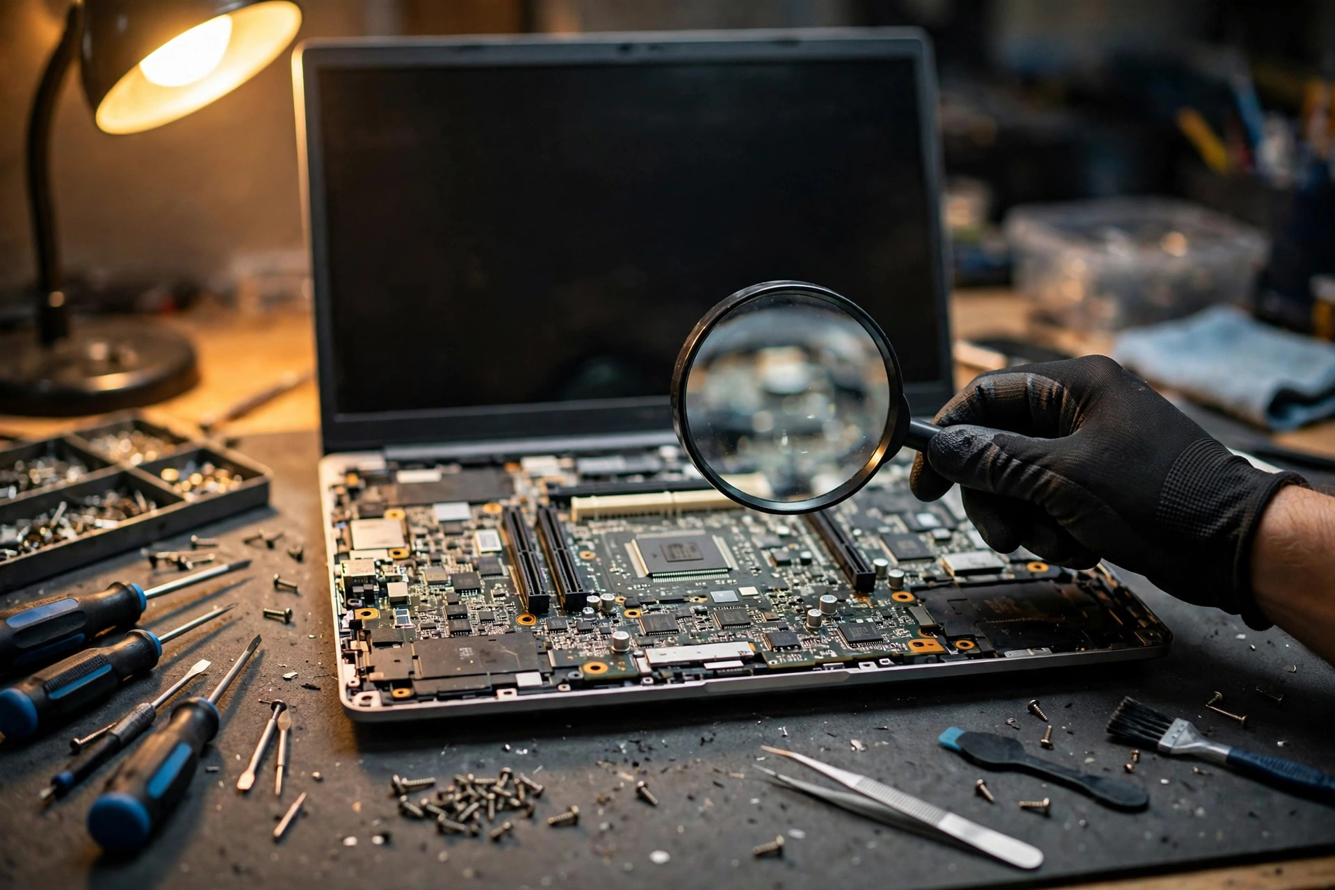
Boundary: this guide covers only the Super I/O functional layer, not the whole board
This guide covers only the Super I/O functional layer. Its scope is fan PWM control, hardware monitoring of temperature, voltage and fan speed, the legacy 8042 keyboard controller function, power-button debouncing and power-on signal handover, lid open and close sensing handover, and legacy serial I/O. Those six functional blocks are the whole main body of this guide. Every other area is mentioned only as a boundary reference and is never developed into a main chapter.
The key honesty point must be stated first. Many modern laptops have already integrated Super I/O functions into the embedded controller chip. For example, the ITE IT5570 series is an EC plus Super I/O combined design. This guide therefore talks about functional blocks, not about a separate Super I/O chip in every machine. Seeing one ITE, Nuvoton or ENE chip on a board does not prove it is a pure Super I/O chip. Not seeing a separate Super I/O chip does not prove the machine has no Super I/O functions. How the functions are distributed in a particular machine must be checked against that model's schematic and service manual.
The areas kept only as boundary references are the embedded controller itself, the platform controller hub, the charging integrated circuit, power sequencing, the processor voltage regulator module, BIOS and UEFI damage, ball grid array solder joints, board short circuits, the keyboard body itself, and a fan body that does not spin. Those areas each have their own dedicated guides. When this guide mentions them, it goes only as far as the handover or the exclusion boundary, and it never rewrites them as main text. When a reader sees a symptom, the first question should be which functional block it belongs to, and the second question should be which layer it belongs to, rather than attributing every symptom to Super I/O at once.
The whole article is limited to user-level external comparison and recording. It never teaches do-it-yourself disassembly, bottom cover removal, display removal, internal cable unplugging, inspection or chip replacement. Whenever words for disassembly appear, they appear only in the prohibiting sense of do not disassemble the machine yourself, hand it to inspection. Any confirmation involving the inside of the board is inspection work. The reader layer does observation, settings comparison, external comparison and recording only. For pricing scope, see pricing. For the inspection process, see diagnostic service.
Chapter 1: Super I/O is a set of functions, not a single part
The historical starting point of Super I/O was to gather a collection of slow, old, but still needed interfaces into one place. Early designs used ISA add-in cards, later designs became built-in board chips connected through the Low Pin Count bus to the chipset side, and newer platforms use the Enhanced Serial Peripheral Interface. That evolution already makes one point clear. The value of Super I/O is not speed, but concentration and compatibility. The things it handles are not fast, but without them, booting, fan control, keyboard input, monitoring, the power button and lid events each start to fail in their own way.
Super I/O must be understood in three layers. The first is the bus layer. Super I/O does not connect directly to the processor high-speed bus. It hangs off the chipset side through LPC or eSPI. If the bus breaks, or the chipset side fails, Super I/O functions can disappear as a group, but that does not prove the Super I/O functional block itself has failed. The second is the functional layer. One functional block can contain several logical devices at the same time, each of which can be enabled or disabled independently. One function failing does not prove the whole block has failed. The third is the firmware layer. In a laptop EC plus Super I/O combined design in particular, behaviour is largely decided by EC firmware. A wrong firmware setting, damaged firmware, or firmware that does not match the BIOS and ACPI tables can look exactly like hardware failure, yet replacing the Super I/O, subject to a written quotation after inspection, will not solve it.
Modern laptops have three physical forms, and they must be stated first, otherwise the whole guide would mislead. The first form is a separate Super I/O chip, seen in older designs and some older laptops: one chip dedicated to Super I/O functions, connected through LPC to the chipset side. In theory, judgement can target the functional block alone, but the bus and the power supply must still be excluded first. The second form is an EC plus Super I/O combined chip, one of the mainstream forms in modern laptops. For example, an ITE IT5570 series EC design carries EC, Super I/O and keyboard controller functions at the same time, and the Nuvoton NPCE and NPCX series also belong to the laptop input and output and EC controller families. Under this form, replacing the Super I/O, subject to a written quotation after inspection, may in practice mean replacing the EC chip, and a new chip often needs firmware written for that model. It is not a matter of soldering a blank chip and expecting it to work. The third form is functions integrated into the platform controller hub, the system on a chip, or another controller, so the Super I/O functional block is split apart. In that case, the number of chip markings must never be used to decide whether Super I/O functions exist. The model's schematic and service manual decide.
| Physical form | Structural character | What it means at user level |
|---|---|---|
| Separate Super I/O chip | One chip dedicated to Super I/O functions, connected through LPC to the chipset side | The functional block is relatively concentrated, but the bus, power and firmware must still be excluded first |
| EC plus Super I/O combined chip | EC, Super I/O and keyboard controller functions share one chip, and firmware is tied to the model | Replacing the Super I/O, subject to a written quotation after inspection, may mean replacing the EC chip, and the firmware source must be confirmed first |
| Functions dispersed into the chipset or system on a chip | Some functions are provided by the chipset or system on a chip side, and the block is split apart | Chip count never decides function ownership, and layering must follow the schematic |
Chapter 2: Why Super I/O failure is so hard to diagnose
The Super I/O functional layer spans four worlds that were originally separate. The first is the pre-boot world: the power button, power-on signal handover, and some platforms' boot sequence triggers, which happen before the operating system loads, and even before the BIOS display appears. The second is the firmware and ACPI world: the power button, lid opening and closing, fan curves, and temperature and voltage monitoring are notified to the operating system or system management programs through ACPI events. The third is the operating system world: the temperature, voltage and speed values read by monitoring software are all translated through Super I/O or EC registers. A wrong reading can be a sensor error, a circuit error, or a register setting error. It is not necessarily a dead chip. The fourth is the legacy world: the 8042 keyboard controller, serial ports and parallel ports are retained for compatibility with old software. A modern laptop may not expose those interfaces, but internal keyboard matrix scanning and boot keyboard logic may still pass through the same functional block.
The diagnostic principle is therefore a single sentence: layer first, blame later. Before the layer has been separated, nobody should say the Super I/O has failed and must be replaced. The layering order runs from outside inward. First comes the periphery and the body itself, including the fan body, the keyboard body, the button body, the lid magnet and Hall sensor, and cabling. Then comes the Super I/O functional block, including PWM output, speed input, temperature and voltage input, the 8042, general-purpose input and output, and serial ports. Then comes the bus and handover layer, including LPC and eSPI, the chipset side, EC firmware, and ACPI events. Then comes the power and reset handover layer, including Super I/O and EC standby power, reset, and the power-on signal chain. Only last comes the chip body and solder joint layer, including internal chip damage, solder joint fatigue and corrosion, and peripheral passive component short circuits. Skipping the outer layers and jumping straight to the last layer is the practice this guide criticises repeatedly.
Chapter 3: Mechanism layer, why it fails
Humidity and corrosion: the slow process closest to Hong Kong
Humid air plus ionic contaminants, such as flux residue, salts in dust, and liquid spill residue, can form an electrolytic environment between neighbouring live traces, with three consequences: insulation resistance falls and leakage appears, dendrite growth lets metallic filaments grow between traces until they short, and conductive anodic filament growth occurs. The Super I/O and EC surroundings contain many high-impedance, low-current signal pins, including general-purpose input and output, sensor inputs and button inputs. Leakage affects such signals far more than it affects high-current power rails. Slight leakage alone can make a temperature input drift, make a general-purpose input misjudge a press or a release, or make a lid state jump, while the power rail voltage can still look normal.
Corrosion is progressive. It does not change overnight from normal to completely dead. The typical progression is intermittent abnormality, then worsening with weather or environmental change, then fixed abnormality. That progression itself is diagnostic evidence. If the symptoms match a humidity or spill history, the corrosion check direction around the Super I/O and EC should be prioritised, rather than replacing a chip at once. The misconception after a spill must be stated clearly. Drying does not equal repair. After the liquid has dried, ionic residue remains, and corrosion continues once power is applied. Drying a machine in the air and using it again after liquid entry is not a safe practice. It should be sent for inspection as soon as possible.
Electrostatic discharge: invisible, immediate, or latent
The human body, clothing and tools carry static charge. On contact with a board, a cable or a connector, discharge can produce an instantaneous high voltage that breaks through a chip's internal gate oxide layer or protection structure. Electrostatic damage has two forms: immediate failure, where function disappears at once, and latent damage, where testing looks normal at the time, but failure arrives early later under normal voltage and temperature stress. Electrostatic damage usually leaves no visible mark, and afterwards it is very hard to prove by eye or by ordinary measurement that electrostatic discharge was the cause. A common situation in repair discussion is that a machine fails to boot after parts are replaced, and the failure is blamed on electrostatic discharge afterwards, when it could equally have been a cable not seated, a screw short, or a power abnormality. The honest wording is that electrostatic discharge is one possible cause, but it cannot be used as a proof-free universal explanation. Diagnosis must first exclude causes that can be measured. Electrostatic discharge can only be listed as a possible cause that has not been excluded, never written as a conclusion.
Power surges and abnormal power
An unstable adapter, a poor-quality third-party charger, a lightning surge arriving through the power cable, or a battery or board power rail short can make Super I/O and EC power pins bear a voltage or current beyond design. The standby power of Super I/O and EC stays live for a long time. Even when the machine is switched off, it does not disconnect. That characteristic makes abnormality on the standby rail especially damaging to Super I/O and EC. A surge occurring while switched off can still damage Super I/O and EC. The surge cause itself belongs to the power area. This guide goes only as far as saying a surge can damage the Super I/O functional block through its power pins, and it does not develop power design. Diagnosis must distinguish two directions: whether the Super I/O functional block itself was broken through by a surge, or whether a peripheral part on the power rail shorted first and dragged the Super I/O power pin voltage abnormal. The handling paths are completely different. Chip heating also has two directions: an internal chip short is the culprit, while an external short dragging the chip is the victim. Replacing a chip without segmenting the fault first can leave the replacement heating again.
Firmware and EC interaction: the false hardware failure that replacing hardware cannot solve
Super I/O and EC behaviour is defined by firmware, including fan curves, temperature thresholds, power-button handling, lid event handling, and keyboard matrix scanning tables. Damaged firmware, a firmware version that does not match the BIOS and ACPI tables, or a failed EC register initialisation can produce symptoms identical to hardware damage. Community documentation of ThinkPad EC firmware records several real EC firmware problem examples, including a fan control loop state not being initialised, a fan control loop making the fan pulse in an annoying pattern, and a tachometer register not being invalidated when leaving a mode. Those examples prove that fan behaviour abnormality can be purely a firmware problem. Replacing the fan or the chip cannot solve it. It needs a firmware update or an ACPI table handling. The division of labour between EC firmware and BIOS must also be separated. The EC runs its own firmware, which can be stored in internal flash or external flash, and every EC function depends heavily on its particular programming. The EC connects to the chipset side through LPC or eSPI. The same chip, written with different firmware, can behave completely differently. If firmware does not match when a chip is replaced, the replacement will still be abnormal. Any symptom that appears only after a BIOS or EC firmware update, or disappears after an update, must first be suspected at the firmware layer. Any case where symptoms stay the same after a chip replacement must go back to firmware and settings, rather than replacing another chip.
Solder joint ageing and peripheral passive parts: the most common but most easily overlooked layer
Components, boards and solder have different thermal expansion coefficients. Repeated temperature rise and fall makes solder joints bear cyclic stress, with creep as the main deformation mechanism. Tin-lead solder, even at room temperature, is already above half its melting point temperature, so creep continues through thermal cycling. Mechanical shock and vibration also cause solder joint fatigue. Repeated small-amplitude, high-frequency vibration accumulates damage. A large-area ball grid array device is more rigid, its joints sit under the package, and when the board is shocked or bent, the joints bear greater stress. A quad flat package gull-wing lead forms stress concentration at the heel and the toe of the lead. Super I/O and EC in laptops commonly use two packages: quad flat package leads are exposed and can be visually inspected, while very fine ball grid array joints sit under the package and cannot be seen by eye. Their failure appearances differ. A quad flat package joint crack can show clues through magnified inspection and light pressure testing. A ball grid array joint crack is almost invisible externally, and symptoms are mostly intermittent and affected by pressure or temperature. Such symptoms are most easily misjudged as chip failure or software problems. The deeper analysis of solder joints is only a boundary reference here. This guide goes only as far as saying solder joint ageing can interrupt Super I/O functions intermittently.
Peripheral passive part and circuit damage are equally important. A divider resistor, filter capacitor, pull-up resistor, protection diode, cable or connector around Super I/O and EC can make one Super I/O function channel fail through a value change, an open circuit or a short circuit, while the chip itself is completely normal. Typical examples include a temperature sensing channel divider resistor changing value and making temperature readings systematically high or low, a general-purpose input pull-up resistor opening and making a button or lid signal float and jump, and a fan tachometer line breaking and making the BIOS report a fan error while the fan body and the Super I/O are both normal. This layer is relatively low cost, does not require moving the chip, and must be excluded before chip replacement. Skipping this layer and replacing the chip directly is a misdiagnosis pattern this guide criticises in particular.
| Cause mechanism | What it acts on | Typical progression | User-level clue |
|---|---|---|---|
| Humidity corrosion | High-impedance signal pins, sensor inputs, general-purpose input and output | Progressive, intermittent becoming fixed, worse in humidity | Spill history, long damp storage history, seasonal worsening |
| Electrostatic discharge | Chip internal gates, protection structures | Immediate or latent, no visible mark | Appears after board or connector contact, but timing alone never proves it |
| Power surge | Standby power pins, peripheral power rails | Sudden, after a storm or a charger change | Charger change history, storm history, other power abnormalities at the same time |
| Firmware interaction | Fan curves, thresholds, button and lid events, scanning tables | Appears or disappears after an update | Firmware update timing, symptoms unchanged after chip replacement |
| Solder joint ageing and peripheral parts | Joints, resistors, capacitors, pull-up resistors, cabling | Intermittent, affected by temperature, pressure and vibration | Triggered by pressing the body, opening and closing the lid, or moving the machine |
Chapter 4: Functional block one, fan PWM control
Fan PWM control works by taking a temperature input and outputting a pulse-width modulation or direct-current control signal to adjust fan speed, while at the same time receiving the fan speed feedback and learning how fast the fan is actually turning. The Nuvoton NCT6779D product description states support for Smart Fan control systems, including Smart Fan first generation and fourth generation, up to five fan speed detections and five fan speed controls. The NCT6791D states six fan speed monitoring inputs, six fan speed controls, and pulse-width modulation and direct-current dual modes. Numbers differ by model. The channel count of one model must never be treated as a universal specification. The Linux kernel NCT6775 driver document for the same family further clarifies control modes: manual mode writes a control value directly, thermal cruise mode adjusts around a target temperature, and Smart Fan fourth generation mode calculates output from multi-segment slopes and multiple temperature and control value data points. That classification makes one point clear. The same set of control pins can behave completely differently according to settings. A wrong setting can make a fan run at full speed permanently, start and stop in jumps, or fail to spin at low temperature. The ITE IT8786E specification summary also states up to five fan speeds controlled through five sets of 256-step pulse-width modulation outputs, monitoring up to five fan tachometer inputs. Two hundred and fifty-six steps means the control value has 256 steps. It is not a two-state on or off control.
Pulse-width modulation and direct current are two different control methods. Pulse-width modulation keeps supply voltage stable and adjusts speed with duty cycle. Direct current adjusts supply voltage directly. Driving them the wrong way, for example driving a pulse-width modulation fan as a direct-current fan, or the reverse, can narrow the speed range, make starting difficult, or make speed feedback abnormal. That is a setting or matching problem, not necessarily a chip failure. What fan failure looks like at functional level, without inferring cause, can be listed as follows. A fan running at full speed permanently can mean control output stuck at a high duty cycle, or a control loop that receives no correct temperature or speed feedback and enters protective full speed. A fan speed that jumps, or starts and stops intermittently, can mean temperature input jumping, tachometer feedback breaking intermittently, or a control mode setting that does not match fan characteristics. A fan that does not follow load changes can mean control output not changing, or an output pin dragged by an external short or open circuit. A fan error reported immediately at boot can mean that some models' BIOS or EC checks tachometer feedback during self-test and reports an error when no feedback is received, but the fan body, cable, power supply or Super I/O input pin breaking at any point can produce the same report. The easiest misjudgement is confusing a fan body that does not spin with a failed Super I/O pulse-width modulation function. The layering key is to confirm the fan body, power, cable and tachometer line first, and only then discuss the Super I/O output and input layer. Without layering evidence, nobody should assign blame.
Chapter 5: Functional block two, the hardware monitoring sensing chain
Hardware monitoring collects board temperature, voltage and fan speed, compares them with thresholds, issues a warning when a threshold is exceeded, and supplies readings to the BIOS, EC firmware and operating system monitoring software. The Nuvoton NCT6779D states up to ten external voltage detection inputs, up to six temperature detection inputs, current-mode plus thermistor temperature sensing, and support for processor temperature forwarding, chipset temperature forwarding, and system management bus master control. The meaning is that temperature does not come from one source only. Processor internal temperature can arrive through forwarding, board temperature can be sensed through a thermistor or diode, and the two readings do not mean the same thing and cannot be compared directly. The NCT6791D states fourteen voltage inputs, six fan monitors, dual current source temperature sensing, programmable hysteresis and set points, and system management interrupt and over-temperature warnings for system protection when over-temperature occurs. The Linux kernel document adds that the same family can have up to twenty-five temperature monitoring sources, of which only up to six are direct sensor inputs, with the rest coming from processor forwarding, chipset and system management bus special sources. Depending on the model, only two to six temperature sources can be monitored and compared with minimum, maximum and critical temperatures. Voltage sensor counts range from eight to fifteen by model. The diagnostic value of that passage is large. A temperature shown by monitoring software is not necessarily a board physical sensor temperature. It may be a forwarded or relayed value. If the source is wrong, the whole overheating judgement will be wrong.
The hysteresis mechanism must also be explained. To prevent a fan starting and stopping frequently when temperature hovers near a threshold, monitoring logic sets a return difference range. A wrong hysteresis setting, or large temperature input noise, can make a fan start and stop frequently, while the chip itself may not be faulty. What hardware monitoring failure looks like can be listed as follows. Readings that freeze, jump or disappear can be caused by an input pin open circuit, short circuit, peripheral divider resistor value change, or sensor failure on one channel. A false over-temperature or over-voltage report that triggers throttling, switch-off or full fan speed can be caused by any one of threshold setting, sensor or input circuit being wrong. Monitoring software showing no fan or no temperature while the system actually operates normally is possible because the monitoring path and the control path are not the same path. Control may be done directly by EC firmware, while monitoring software only reads through another interface. Failing to read does not prove control has failed. The easiest misjudgement is treating a monitoring software reading as physical fact. The correct practice is to cross-check at the same time with a second method, such as the BIOS monitoring page, EC register readings, or actual voltage measurement, and first confirm the reading source, meaning which sensor and which channel. Replacing a chip on one program and one number alone is a typical misdiagnosis.
The sensing chain can be divided into four inaccuracy modes. The first is the ghost reading from an unwired input. One temperature, voltage or fan column stays extreme, frozen or jumps without pattern, while other columns stay normal, and changing monitoring software still shows the same column abnormal. The mechanism is that monitoring software lists every column the chip supports, which does not mean the board is wired for every column. The second is sensing element or divider chain drift. Readings show a systematic offset, staying high or low for a long time, rather than jumping randomly. When several related columns drift together, a shared reference voltage or shared circuit problem should be suspected first. A thermistor reading depends on a divider or current source circuit, and a series resistor, connector contact resistance, circuit corrosion or sensor characteristic drift can all change the converted result. The third is several programs polling at the same time and making the chip stop responding. Monitoring values freeze while running, and only restart restores them. Opening two monitoring, lighting or fan control programs at the same time makes this easier to occur. These are community cases. They cannot be applied directly to a laptop EC, but the mechanism justifies the exclusion step of closing repeated monitoring software before judging. The fourth is a fan strategy dragged by a wrong source. Fan behaviour does not match the heat a user feels. For example, the body does not feel hot but the fan runs at full speed, or the body feels very hot but the fan is slow to speed up. A multi-segment slope control such as Smart Fan fourth generation calculates output from the selected temperature source. If the selected source is an unwired input or a faulty sensor, the fan will follow the wrong temperature.
Chapter 6: Functional block three, the legacy 8042 keyboard controller function
The 8042 was originally the keyboard controller microcontroller of the IBM PC AT. It later became a logical function inside Super I/O and EC: handling keyboard scan codes, PS/2 keyboard and mouse where present, and historical system control functions. For input and output ports, the data port is hexadecimal 60, and the status and command port is hexadecimal 64. Reading and writing the same port address can map to different internal registers, depending on read or write direction. Community documentation of the 8042 lists the use of this port group in detail, including output port commands for reading the output port, writing the output port, and writing a particular value to trigger processor reset. The output port bit definitions include bit zero as the system reset output, which should normally stay at one, since pulling it low locks the system; bit one as the A20 gate output; bits two and three as the second PS/2 port clock and data; and bit four as the first PS/2 port output buffer full, corresponding to interrupt one. That table explains why a keyboard controller can affect booting. The A20 gate and system reset were originally carried by its general-purpose input and output pins as extra duties. The historical role of Gate A20 was to control whether the processor could access memory addresses above one megabyte, through the A20 address line. The old error message 8042 Gate A20 Failure meant the BIOS could not switch the processor into protected mode through the keyboard controller. Modern systems no longer rely on that path for daily operation, but boot self-test and compatibility layers may still touch the related logic.
Need a laptop repair expert?
Free diagnosis · Transparent pricing · No fix, no fee · 180-day warranty
The actual form in laptops must be stated clearly. A laptop built-in keyboard does not go through an exposed PS/2 port. It goes through keyboard matrix scanning into the EC and keyboard controller functional block. The ITE IT8510E EC specification catalogue shows keyboard scanning related registers, for example a keyboard scan input control register. That means a laptop keyboard problem can be a matrix scanning layer, EC firmware layer or cable layer problem. It must not be attributed to a failed 8042 in general. In modern laptops, the legacy 8042 function actually does four things. First, built-in keyboard matrix conversion: the EC reads the keyboard matrix directly, converts raw key positions into PS/2 scan codes, and hands them to the system through the data and command ports. Function keys are usually handled inside the EC and are not sent directly to the processor. Second, a PS/2 compatibility layer: even though the physical PS/2 socket has disappeared, the 8042 command interface still exists as a compatibility protocol between the BIOS, operating system drivers and the EC. USB keyboards and mice in some modes are simulated as PS/2 devices through that compatibility layer. Third, system control extra duties: reset and power event concepts historically derived from spare 8042 pins have evolved in the modern EC into more complete power, fan and battery management, but the command interface lineage is still 8042. Fourth, an early boot keyboard initialisation sequence: the BIOS performs keyboard initialisation through 8042 commands, with command details differing by BIOS, and they must not be written as a universal process.
What 8042 failure looks like can be listed as follows. A boot keyboard error or keyboard controller self-test failure belongs to the boot self-test stage, but it can equally be caused by the keyboard body, cable or EC firmware. Single key garbling, ghost keys, or a whole row or column of keys failing look more like matrix scanning layer characteristics than 8042 core damage characteristics. A system reset or A20 related boot abnormality is rare. Modern laptops seldom show such error messages directly, and when they appear, BIOS and EC firmware and the reset circuit must be excluded first. The easiest misjudgement is assigning anything with the word keyboard to Super I/O. The task boundary already states that the keyboard body itself is outside this guide's main body. The Super I/O functional layer covers only 8042 logic and scanning handover. Keyboard body, keycaps, membranes and cable damage must be excluded first. A distinguishing table can help readers layer the problem. Single keys failing, double-typing or one area failing look more like the keyboard body layer. A whole built-in keyboard with no response, while an external USB keyboard works, still requires excluding the built-in keyboard cable and connector first, before considering EC keyboard matrix scanning, the 8042 command interface, or an EC firmware state stall. A keyboard that responds at boot but not after entering the operating system, or the reverse, looks more like a BIOS initialisation and operating system driver handover problem. All function key combinations failing while ordinary letter keys work looks more like EC internal handling of function keys or a settings layer. Keyboard plus power button plus fan control failing together seldom points at a single keyboard, and looks more likely to point at a shared EC plus Super I/O functional block or EC standby power and state problem, although shared cabling and connectors must still be excluded. The writing red line is never to write that the keyboard failed because the 8042 failed. The correct wording is that built-in keyboard signals must pass through the 8042 compatible functional layer inside the EC, and the keyboard body, cable, EC functional layer and driver layer are all possible, so layering exclusion is required. It must also never be written that modern laptops have no 8042, because the command interface still exists. The correct wording is that the physical separate 8042 chip has been absorbed by the EC, but the 8042 command and port semantics remain a subset of the EC.
Chapter 7: Functional block four, power-button debouncing and power-on signal handover
The power button works by converting a mechanical button press into a clean, single, correctly timed power-on, wake or forced switch-off event, and handing it to the chipset and EC power state machine. A mechanical button contact bounces several times at the instant of pressing and releasing, producing a rapid series of opening and closing noise pulses. If those pulses were treated directly as several presses, the system would misjudge them as several switch operations. Debouncing is therefore a necessary logic: only after the signal has stayed stable for a period is it confirmed as one valid press. The Intel 800 series PCH datasheet description of the power button signal is the most concrete first-hand timing evidence in this guide. The power button signal operates as the fixed power button in the ACPI specification, with a 16 millisecond debounce on its input. If the debounce mode setting is zero, after any valid falling edge of the power button signal, the state transition only starts after 16 milliseconds of debouncing. If the debounce mode setting is one, the state transition starts immediately after the valid edge, and further falling edges within the following 16 milliseconds are ignored. In the G3 state, pressing the power button has no effect, because there is no power and the event is not latched. During G3 exit, the power button pin must stay not valid for at least 500 microseconds after the chipset reset release, and only a valid time of at least 150 microseconds afterwards is treated by the chipset as a valid wake event. If the power button stays pulled low for at least 4 seconds, after sampling through the debounce logic, the chipset unconditionally moves to the off state, even if the power-good signal is not valid. Because of internal chipset delay, up to about 1.3 seconds more after the 4 seconds may pass before the move to the off state starts. During sleep signal stretching, the power button timeout extends to 9 to 10 seconds, to avoid a user holding the button while waiting for wake and accidentally triggering forced switch-off.
Those numbers apply only to the chipset behaviour described in that Intel 800 series PCH datasheet. They cannot be treated as universal numbers for all laptops, all chipsets, or all EC designs. The EC side debounce time and power-on signal names differ by model and must be checked against that model's schematic. A universal laptop EC debounce time has not been verified, and this guide will not write one universal number. The handover chain concept is as follows: the power button, through EC or Super I/O general-purpose input and debouncing, through EC firmware judgement, through a power-on enable signal, through the chipset sleep and reset state machine, through processor reset release, and through BIOS execution. If any link in the chain breaks, the symptom can be pressing the button with no response, but the break point is completely different in each case. What power button failure looks like can be listed as follows. Pressing once with no response can mean debounce logic receiving no clean edge, a general-purpose input pin open circuit, button body poor contact, or a broken handover signal chain. Pressing once becoming several switch operations or automatic restart can mean failed debouncing, severe button contact bounce, or general-purpose input noise interference. A long press failing to force switch-off, or a single press switching off at once, can mean an abnormality in the forced switch-off logic input or the chipset side state machine, but that can also be a chipset layer problem beyond this guide's main body, and it should be handed to the related guide. Intermittent failure to boot, sometimes working and sometimes not, is hardest to separate among debounce edge conditions, unstable power, and connector poor contact, and it needs repeated testing under fixed conditions to separate them. The easiest misjudgement is confusing a faulty button body with failed Super I/O or EC debouncing. The mechanical button, cable and button small board are the outermost layer and must be excluded first. The chipset side power button behaviour and the EC side debouncing are two layers, and the chipset datasheet 16 milliseconds must never be used directly to assert the EC debounce time.
The textual distinction between debounce failure and button mechanical failure is where this chapter is easiest to write wrong. Button mechanical failure includes switch contact oxidation, wear, sticking, and cable breakage. Its characteristics are usually related to press feel: the press feels different, a particular angle is needed, or the machine only boots while the button is held down. Such problems need no chip damage to explain them. Debounce or general-purpose input failure can occur while the switch itself is normal, but bounce signals are not filtered, or the general-purpose input line is disturbed by noise, so the EC receives several edges. Its characteristics are usually one press triggering several events, or very short noise triggering switch operations, while press feel stays normal. The ITE IT8718F specification explicitly states that general-purpose input mode supports switch debouncing, which proves debouncing is part of Super I/O and EC general-purpose input function, not a purely software concept. Handover failure means the button event is correctly received, but the later signals the EC sends to the chipset and power circuits are not completed. Its characteristic is a button response, but a boot process stopping midway. At that stage, work should stop immediately and be handed to power sequencing, chipset and BIOS divisions. It must not be inferred in the Super I/O guide which signal pin has failed. The writing red line is never to write that a debounce capacitor has failed, as a specific component conclusion without schematic support. Unless a model's schematic states which capacitor handles debouncing, the wording can only be that the debounce and general-purpose input chain needs board-level inspection.
| Power button pattern | More likely distinguishing direction | What to record at user level |
|---|---|---|
| Pressing produces no response, no light, no fan sound, and the charging light is also abnormal | Button, cable, EC standby power, EC itself stalled, or a more upstream power problem | Charging indicator, mains versus battery behaviour, button feel |
| Pressing produces light, the fan spins briefly then stops, and then no picture | Handover has started but later signals or power have not completed | How long the fan spins, whether there is a picture, whether repeated boot attempts behave the same |
| One press boots, but one press easily becomes two actions | Button poor contact, cable poor contact, general-purpose input debounce setting or circuit noise | Press feel, whether the casing presses the button, whether it happens every time |
| A short press produces no response, but a long press produces a response, or the reverse | Easily confused with the 4 second forced switch-off mechanism, or an operating system power button action setting difference | How many short presses succeed once, and the operating system power setting |
| Plugging in mains switches the machine on at once, or it switches on without pressing | Do not say at once that the button is shorted; also consider BIOS mains recovery setting, wake events, and EC standby state abnormality | BIOS mains recovery setting, wake sources, whether the casing presses the button |
| Keyboard, charging indicator and boot fail together, and disconnecting power restores briefly | EC firmware or state stall is possible, but recovery after disconnection does not prove EC failure | How long recovery lasts, and how often it recurs |
Chapter 8: Functional block five, lid open and close sensing handover
Lid sensing works by detecting the laptop lid open and close state and notifying the operating system through an ACPI event to take the corresponding action, such as lid close sleep, lid open wake, or display switch-off. The ACPI specification lists the lid switch as a generic hardware event feature, limited to mobile systems, and provides a control method lid device and power and sleep button devices. Lid events, like power button events, belong to ACPI generic event logic, notified to the operating system through a system control interrupt, or in an older mode through a system management interrupt handled transparently to the operating system. The ACPI embedded controller interface specification further clarifies that EC firmware must be able to queue notification events, and the EC only places an event notification into the output buffer after receiving a query command from operating system power management or a system management interrupt handler. That means a lid event does not enter the operating system the instant the sensor changes. It must pass through EC detection, setting an event flag, operating system or system management interrupt query, EC reply to the query value, and operating system execution of the corresponding control method. Any link in that chain, including the sensor, EC input, EC firmware, ACPI table or operating system setting, failing can appear as no response to lid close or failure to wake on lid open.
At the sensor body layer, laptop lid sensing commonly uses a Hall sensor sensing a magnet inside the lid, or a mechanical switch. That layer belongs to the sensor body and magnet position, not to the Super I/O chip body. The Super I/O and EC functional layer only receives the sensor signal, mostly through general-purpose input, and converts it into an ACPI event. A universal lid sensor implementation has not been verified. Both reed switch and Hall sensor implementations exist, and which one a particular model uses must be checked against its service manual and schematic. This guide will not write one as universal. At the operating system setting layer, the lid close action, including sleep, hibernate, do nothing, or switch off, is an operating system setting, not a Super I/O hardware decision. If it is set to do nothing, the machine not sleeping on lid close is normal behaviour, not a fault. What lid failure looks like can be listed as follows. Lid close producing no sleep or no display switch-off can be caused by five causes with identical symptoms: the sensor not receiving the magnet, a general-purpose input abnormality, an EC firmware event flag abnormality, an ACPI table reply abnormality, or an operating system setting of no action. Lid open failing to wake, or waking and then sleeping again at once, can be a lid state report opposite to reality, sensor edge jitter, or repeated ACPI events. Intermittent automatic sleep or wake can be lid sensor edge conditions, magnet displacement, or cabling wear through the hinge area. The hinge area is a laptop-specific mechanical stress point and deserves special attention, but it belongs to the cabling and mechanical layer, not to the Super I/O chip layer. The easiest misjudgement is replacing the Super I/O, subject to a written quotation after inspection, or EC as soon as lid close produces no response. Before any Super I/O replacement, subject to a written quotation after inspection, the correct order is to check the operating system lid setting first, then the sensor body and magnet, then the general-purpose input and EC event chain, and only last consider the chip layer.
Sleep states must be explained first, because different sleep states have different wake paths. The working state includes low-power idle, where the processor is in a power-saving state and the chipset can take extra power-saving actions, but the system has not entered traditional sleep. Traditional sleep is suspend to memory, where processor state is not retained, memory state is retained, and wake restores the pre-sleep state. Hibernate is suspend to disk, where neither processor nor memory state is retained, state is written to disk and then switched off, and wake must restore from disk. Soft off is a state where state is not saved, only the logic needed for restart is retained, and a full boot is needed to recover. Mechanical off is a state where everything except the real-time clock is disconnected, and no wake event is possible. ACPI also defines sleep and wake control methods, including preparing for sleep, transitioning to a state, system wake, and system wake source, so the operating system can determine which event caused entry into the working state. When writing, the wake source concept can be used as the main distinguishing axis: which event actually woke the machine.
Four confusion patterns form the core of this chapter. The first is a lid falsely reporting closed. The machine sleeps or blacks out for no reason. While typing, moving the machine, or pressing the palm rest, the screen suddenly blacks out for one to two seconds and then recovers, or enters sleep directly, without closing the lid. The mechanism is a sensor falsely triggered by magnetic interference, a loose sensor, poor cable contact, or body bending changing the sensing distance, so the EC misjudges the lid as closed and issues an ACPI lid event. The distinguishing method is to set the operating system lid close action temporarily to do nothing and see whether the blackout or sleep disappears, check for nearby magnetic items including magnetic watch straps, bag magnetic clasps and magnetic stands, and check whether the screen frame magnet position has shifted or the hinge is loose. That test can only prove the lid event is the trigger source. It cannot prove whether the sensor or the EC is faulty. The second is a lid falsely reporting open. The machine wakes itself or sleeps unstably. The lid is clearly closed and nobody touches the machine, yet the machine wakes from sleep by itself, or gets warm and drains power inside a bag. The mechanism is a lid sensing signal toggling repeatedly at its threshold, or other wake sources being mistaken for a lid problem. The distinguishing method is to check the operating system wake record and disable suspicious wake sources one by one, including USB wake, Bluetooth wake, network wake and wake timers, and see whether the problem disappears. The third is a lid really closed, but the machine does not sleep or switch the display off. Possible directions include the operating system lid close action set to do nothing, an external display or power setting overriding the lid close action, a sensor with no response at all, or the operating system not receiving an ACPI lid event. The distinguishing method is to check the operating system lid setting first, with mains and battery set separately, then check the external display setting, and only last suspect the sensing chain. The fourth is a lid opened but the machine does not wake. The screen stays black after opening, but fan sound, drive light or keyboard light suggests the machine may still be running. Pressing the power button also produces no response, or a long press is needed to switch off and boot again. Possible directions include a lid open event not delivered correctly, a stalled wake process, a display output problem, which is already beyond the Super I/O range and should be handed to the display guide, or an EC wake handover problem. The distinguishing method is to test with an external display, separating whether the machine did not wake or the built-in display did not show, check the wake record, and record whether the machine was in traditional sleep or low-power idle before closing, because the two sleep wake paths differ and must not be mixed.
Chapter 9: Functional block six, legacy serial I/O
Legacy serial I/O exists for compatibility with old devices and for debugging, retaining serial ports, parallel ports, infrared and other low-speed interfaces. Many modern laptops no longer expose those interfaces, but the Super I/O functional block may still retain the related logical devices, and the BIOS settings page may still show a Super I/O Configuration option. The Nuvoton NCT6779D supports two serial ports, a parallel port, infrared receive and transmit and learning and wake functions, and general-purpose input and output. The ITE IT8718F has two 16C550 serial ports, a parallel port, forty-eight general-purpose inputs and outputs, and SmartGuardian automatic fan control. The 16C550 is a classic compatible serial port model with transmit and receive buffers, and that detail explains the compatibility basis of serial port function. The ITE IT8786E has six 16C550 serial ports. Serial port counts differ by model. Never assume Super I/O means two communication ports.
For bus evolution, ISA was followed by LPC, and then by eSPI. The Intel eSPI base specification states at the outset that before eSPI, the EC, baseboard management controller and Super I/O connected to the chipset through LPC. eSPI provides a migration path moving LPC devices to the new interface, and carries EC and baseboard management controller out-of-band messages as in-band messages through eSPI, replacing the system management bus in that use, and eSPI also supports runtime flash sharing. Manufacturer technical notes also state that eSPI is intended to replace the LPC host interface completely, with advantages including fewer pins, support for 1.8 volt input and output, more efficient coordination with high-speed transmission, and fewer sideband signals. The laptop reality is that even when a modern laptop retains Super I/O and EC serial port logic, the physical communication port is mostly not exposed. Serial ports are used more for internal debugging, production testing, or particular expansion uses. A communication port not appearing is therefore mostly not a fault in a laptop, but a design that never exposed it.
What legacy failure looks like can be listed as follows. A Super I/O option disappearing from the BIOS settings page, or being impossible to enable, can be a Super I/O logical device not enumerated correctly, an LPC or eSPI bus abnormality, or damaged BIOS settings, and those three must be separated. An external serial device not being recognised requires separating serial port settings, address and interrupt conflicts, drivers, and circuits into four layers. Laptops expose communication ports very rarely, and when such a complaint appears, the first step is to confirm whether that model itself has an exposed interface. An interruption of serial output for debugging belongs to production or repair debugging scenarios, beyond ordinary user scenarios, and debugging use must not be written as an ordinary user function. The easiest misjudgement is treating no communication port as Super I/O failure. A modern laptop with no exposed communication port is a normal design, not fault evidence. Another layer to separate is that the chipset itself also provides serial input and output controllers, which are a different layer from the traditional Super I/O serial ports, and they must not be confused.
| Legacy function | Actual meaning in a modern laptop | User-level misjudgement |
|---|---|---|
| Serial port logical device | Compatibility, debugging, production testing, EC communication, physical port mostly not exposed | Treating no exposed port as a fault |
| Parallel port logical device | Old device compatibility, physical port very rarely exposed in modern laptops | Treating no option on the settings page as chip damage |
| Logical device enable and disable | Each logical device can be enabled or disabled individually; when disabled, input is suppressed, clock is stopped, and output is high impedance | Treating a disabled setting as hardware failure |
| LPC to eSPI migration | Old devices connect through the new interface, and out-of-band messages become in-band messages | Applying an LPC era description directly to an eSPI platform |
Chapter 10: Symptom pattern comparison table, one symptom can map to several cause layers
The reading method is that one symptom can map to several cause layers, and the priority exclusion order in the table is the key point. Do not read only the first row and assign blame. The table contains no incidence numbers, because the related statistics have not been verified. The core technique of user-level comparison is to record the affected list and the unaffected list at the same time, and hand both lists to inspection. Handing only the affected list forces inspection to spend extra time asking for the unaffected list. When both lists are complete, the layering direction becomes much clearer.
| Symptom pattern | Possible functional block | Priority exclusion order, outside inward | Most easily misjudged as |
|---|---|---|---|
| Pressing the power button produces no response at all, no light, no fan, no action | Power-button debouncing and power-on signal handover | Button body, cable and button small board, standby power reaching EC and Super I/O, power-on signal chain, chipset and power sequencing handover, chip layer | Immediately asserting that Super I/O or EC has burnt out |
| One press boots, but booting intermittently fails, sometimes works and sometimes not | Power-button debouncing and power-on signal handover, solder joints and connectors | Button contact bounce and poor contact, cable and connector contact, standby power stability, solder joint intermittency | A software or BIOS problem |
| Fan runs at full speed permanently, not following load changes | Fan PWM control, hardware monitoring | Cross-check whether the temperature input reading is real, fan body and speed feedback, control mode setting, EC firmware fan curve, Super I/O control output layer | The fan body itself failing |
| Fan speed jumps, or starts and stops intermittently | Fan PWM control, hardware monitoring | Temperature input noise and sensor, speed feedback intermittency, hysteresis setting, EC firmware problem, solder joints and cabling | A cooling system problem, replacing the cooling module without layering |
| Boot immediately reports a fan error | Fan PWM control, speed monitoring | Fan body, cable and power, speed line, BIOS and EC speed check logic, Super I/O speed input layer | Immediately replacing the fan or the chip as a two-choice gamble |
| Monitoring software temperature or voltage readings freeze, jump or disappear | Hardware monitoring | Reading source, meaning which sensor and which channel, a second reading method for cross-checking, sensor and divider resistor, Super I/O input layer and bus | Processor or board overheating, asserted from a single reading |
| False over-temperature report triggers throttling or automatic switch-off | Hardware monitoring, fan control | Temperature source and threshold setting, sensor and divider resistor, EC firmware threshold, a real cooling problem handed to the cooling area | Immediately replacing the Super I/O, subject to a written quotation after inspection |
| Single keys garble, ghost keys, or a whole row or column fails | 8042 and keyboard matrix scanning handover | Keyboard body, membrane and cable as boundary, matrix scanning table and EC firmware, 8042 logic | A failed 8042 chip |
| Boot reports a keyboard error or keyboard controller self-test failure | Legacy 8042 function | Keyboard body and cable, EC firmware initialisation, 8042 logic and reset circuit | A failed BIOS, rewritten without layering |
| Lid close produces no sleep or no display switch-off | Lid open and close sensing handover | Operating system lid close setting, lid sensor body and magnet position, hinge-area cabling, EC event chain and ACPI reply, chip layer | Failed Super I/O or EC |
| Lid open fails to wake, or wakes and then sleeps again at once | Lid open and close sensing handover | Operating system sleep and wake settings, whether the lid state report is opposite to reality, sensor edge jitter, ACPI event chain | A display or sleep system problem, without layering |
| Super I/O options disappear from the BIOS settings page | Legacy serial I/O, bus | Damaged BIOS settings and version, LPC and eSPI bus, Super I/O logical device enumeration | A failed board, as a blanket blame |
| An external serial device cannot be recognised, only for models with an exposed communication port | Legacy serial I/O, serial port | Confirm whether that model itself has an exposed interface, serial port address and interrupt setting, driver, circuit | Failed Super I/O |
| A group of Super I/O functions disappears together, fan plus monitoring plus keyboard plus boot all abnormal | Bus, power, chip layer | Standby power, LPC and eSPI bus, EC firmware, chip layer | Replacing parts function by function, treating the head for a headache |
| A Super I/O or EC chip heats abnormally | Chip layer, peripheral short circuit | Which power rail is shorted through peripheral capacitors and switching parts, chip power pin voltage, internal chip short considered last | Replacing the chip from heating alone, which may heat again after replacement because the culprit is in the periphery |
Chapter 11: Layered exclusion process, outside inward, without skipping levels
Level zero is history taking and recording. It involves no internal operation, and everyone should do it first. When did the symptom start, was it sudden or progressive, and was there a prior cause such as a spill, a drop, a storm, a charger change, or a BIOS or EC firmware update. Is the symptom fixed or intermittent, and is it related to temperature, humidity, pressing the body, opening and closing the lid, or plugging and unplugging power. Which functions fail together, and which functions still work. Group disappearance and single function abnormality point in completely different diagnostic directions. Photograph or write down the exact error message wording, such as a fan error or keyboard error code, the BIOS version, and the EC firmware version if it can be queried, and hand them to inspection together.
Level one is periphery and settings exclusion, without involving the inside of the board. An external keyboard and mouse test: if an external keyboard works while the built-in keyboard fails, the problem is more likely in the built-in keyboard body, cable, or matrix scanning layer than in the 8042 core. Operating system settings check: lid close action, sleep and wake settings, and fan mode software settings, such as silent and performance modes in the manufacturer control centre, to exclude a false fault caused by a setting of no action. BIOS settings check: test again after loading BIOS defaults, noting that original settings must be recorded before loading defaults, and settings must not be changed randomly without knowing the consequences. Firmware version check: compare with the manufacturer website to confirm whether the BIOS and EC firmware is a version known to have a problem. If symptoms appeared after an update, that timing association must be recorded explicitly. Keep only one hardware monitoring tool, close other monitoring, lighting and fan control resident programs, and observe whether the problem disappears. That step can exclude freezing caused by several programs polling at the same time.
Level two is mechanical and external interference exclusion. Power button feel: whether it sticks, rebounds poorly, or needs a particular angle. Magnetic items near the lid: magnetic watch straps, bag magnetic clasps, magnetic stands, and other magnets. Hinge looseness, screen frame magnet displacement, and palm rest pressure. Cable connector looseness is limited to persons with repair experience following the model manual. This guide will not teach readers to handle internal cables themselves. Level three is sensing chain cross-comparison. For the same temperature or speed, compare two independent sources, such as processor internal temperature against the Super I/O temperature column, or a BIOS display against operating system monitoring software. Look at trends, not single points. The change range between idle and load is more meaningful than a single number. A frozen column, an extreme column, or a column that does not change with load should first be suspected as an unwired input or a setting error. If fan behaviour and readings do not match, for example readings saying very hot but the fan not responding, one link between the sensing chain and the control chain must be broken.
Level four is the power and lid event chain comparison. Use the operating system wake record to distinguish wake sources, including lid, power button, USB, Bluetooth, network and timers. Set the lid close action temporarily to do nothing, to distinguish whether the lid event is the trigger source. Follow the model manual for the correct EC and power reset procedure, record how long recovery lasts after reset, and only consider board-level inspection if it recurs repeatedly. Distinguish traditional sleep from low-power idle, because their wake paths differ, and experience from one sleep type must not be used to judge a machine of the other type. Level five is firmware and settings layer verification. Compare with that model's schematic and service manual to confirm whether Super I/O and EC logical device enable settings, fan mode settings and temperature threshold settings are reasonable. If EC firmware damage or version mismatch is suspected, update or rewrite firmware only through the manufacturer's official route. Firmware from an unknown source must not be used, because wrong firmware can brick a whole board. If symptoms disappear after a firmware update, the conclusion should be written as a firmware layer problem, not as a repaired Super I/O hardware failure. Level six is board-level inspection, and this guide goes only this far. It confirms architecture from the schematic, checks standby power, crystal, reset signals, general-purpose input pull-ups, sensor circuits and cable connector surroundings, and confirms chip model, revision, firmware source and programming need before any quotation can be made. Operations after level six do not belong to reader self-operation. The guide must state clearly that at this point the machine should be sent for inspection, and readers must not be taught to handle board chips themselves or to program EC firmware themselves.
Only when the following conditions hold at the same time can Super I/O replacement, subject to a written quotation after inspection, be considered. Power has been confirmed normal. Peripheral passive parts, cabling, sensors and the button body have been excluded. The bus and chipset side have been excluded or handed to the related guide. The firmware and settings layer has been verified. Inspection evidence points at one Super I/O functional block input or output layer abnormality, rather than a group abnormality without distinction. Even at this level, a quotation must still state that Super I/O replacement is subject to a written quotation after inspection, and the following limits must be stated in advance, including chip source, firmware handling, the follow-up plan if replacement still fails, and the risk of rework to surrounding parts. For pricing scope, see pricing. For the inspection process, see diagnostic service.
Chapter 12: Common misdiagnoses and traps
Trap one is attributing USB problems to Super I/O. Some second-hand blog articles claim Super I/O handles USB ports, and list USB failure as a Super I/O failure symptom. That claim is misleading for modern laptops. USB controllers are mainly provided by the chipset or system on a chip side. The Super I/O functional layer is not the main USB controller. Attributing USB failure to Super I/O sends diagnosis in the wrong direction and delays investigation of the real causes, including the chipset, the USB physical layer, power, and drivers. When writing, that claim must be corrected, not copied from second-hand blogs.
Trap two is treating a monitoring software reading as physical fact. Temperature, voltage and speed shown by monitoring software can come from several paths, including processor forwarding, chipset, system management bus, and direct sensors. A single program, a single reading and a single moment can never be evidence for chip replacement. Cross-checking is required. Trap three is replacing a chip immediately from chip heating. Chip heating has two directions: an internal chip short is the culprit, and an external short dragging the chip is the victim. Replacing a chip without segmenting the fault first can leave the replacement heating again, wasting a chip and a rework risk. The IT8987 discussion thread in community repair discussion is an instance teaching example for this trap, where several replies pointed out that the rail and the peripheral part shorted must be confirmed first, and heating alone must not assign blame.
Trap four is ignoring that a blank chip needs firmware. The ITE IT8987 repair discussion points out a key reality: some EC and Super I/O chips contain programs, and a new chip may not be directly usable. Some repair workers said a same-board source chip was needed, while some suppliers claimed a particular version could replace directly, and the claims were inconsistent. IT5571VG product information also states clearly that after assembly, corresponding firmware has to be programmed through a specified interface according to board architecture before the system cycle can start. The conclusion is that replacing a chip does not mean only replacing hardware. Firmware source, version and writing method must be clarified before quotation, otherwise a replacement that still fails to boot becomes a dispute over responsibility. Trap five is treating no communication port as a fault. A modern laptop with no exposed communication port is a normal design, not Super I/O failure. A BIOS settings page showing no Super I/O option can also mean that model simply has no exposed related logical device, not chip damage. Trap six is treating a settings problem as a hardware problem. Fan mode software settings, operating system lid close settings, and BIOS fan curve settings can all produce symptoms identical to hardware failure. Replacing parts without checking settings is the most expensive misdiagnosis.
Trap seven is treating intermittent symptoms as software problems, or the reverse. Intermittent symptoms have three common roots: solder joint fatigue affected by temperature and pressure, connector poor contact affected by vibration and opening and closing, and corrosion leakage affected by humidity. Their triggering conditions differ, and history taking must ask clearly under which conditions symptoms appear or disappear, rather than writing vaguely that they sometimes work and sometimes do not. Trap eight is applying desktop Super I/O experience directly to laptops. Desktop experience with NCT6779D, NCT6791D and IT87 series, including separate Super I/O chips and exposed communication ports, cannot be applied directly to a laptop EC plus Super I/O combined design. Packages differ, firmware storage methods differ, and keyboard connection methods differ, so diagnostic methods must be adjusted accordingly. Trap nine is over-interpreting boot self-test error codes. Old boot self-test errors, such as 8042 Gate A20 Failure and keyboard controller self-test failure, appearing on a modern laptop must not be judged directly against a manual from decades ago. The definition of that error code in that model's service manual and the field replaceable unit replacement order must be confirmed first. A manufacturer service manual symptom to field replaceable unit index lists replacement order by most likely cause first, and replacing in the wrong order wastes time and parts. Trap ten is treating a chip marking prefix as a model conclusion. Different revisions in the same series can have completely different firmware and programming needs, and community discussion shows suppliers disagreeing on whether IT8987 has preloaded programs. Trap eleven is treating brief recovery after disconnecting power and reconnecting as a confirmed EC failure. Recovery can only prove a state can be reset. It cannot prove which hardware is damaged. Only repeated occurrence has board-level inspection value. Trap twelve is treating an old 8042 function table as a modern fault list. Old functions such as A20 and the computer speaker have changed roles in modern laptops and must not be copied as they are.
Chapter 13: Hong Kong context, humidity, commuting vibration, local parts and end-of-life reality
Hong Kong humidity is a long-term background factor, together with condensation caused by temperature differences between air-conditioned rooms and outdoors, keeping boards in a high humidity environment for a long time. Engineer forum experience sharing notes that in a non-air-conditioned Hong Kong warehouse environment, silver-plated radio frequency parts without dry packaging could turn black within weeks, that ENIG boards are relatively more durable, but non-wiping contacts can still show poor contact after long idle periods. That is only individual experience sharing, not Hong Kong statistics, and this guide will not write it as statistics or ranking. The specific meaning for Super I/O is that high-impedance signal pins around Super I/O and EC are most sensitive to leakage. Slight leakage from humidity can already make temperature readings drift, general-purpose inputs misjudge, and lid states jump, while power rails may still look normal. Symptoms worsening in humid seasons and easing in dry seasons are important history taking clues. User education points include not storing a long-unused laptop near windows, near bathrooms, or in a storage room without air conditioning; not relying on air drying alone after liquid entry, and sending it for cleaning inspection as soon as possible; and watching for condensation risk when moving from an air-conditioned room outdoors. This guide provides no specific temperature difference numbers, because the related numbers have not been verified.
For commuting vibration and daily carrying, laptop daily use includes backpack carrying, subway commuting, opening and closing the lid, and holding one corner of the body with one hand. Those actions bend boards, wear hinge-area cabling, and accumulate solder joint fatigue. Solder joint fatigue literature notes that portable electronic products, because they are small, light and easy to slide, are more likely to collide and drop in use, and repeated small-amplitude, high-frequency vibration causes vibration fatigue. The specific meaning for Super I/O is that lid sensor cabling passes through the hinge area and long-term opening and closing can wear it, power button cabling and keyboard cabling connectors can loosen under vibration, and Super I/O and EC solder joints can show intermittent poor contact under board bending. Those are all peripheral layer problems, with far lower handling cost and risk than chip replacement, and they must be excluded first. History taking points include whether the machine has been dropped, struck, kept under pressure at the bottom of a backpack for a long time, or habitually held by one side with one hand. That history is important for judging solder joint and cable layer likelihood.
Local parts and end-of-life reality are described honestly in this guide. Super I/O and EC chips are mostly model specific. Within one family, firmware and pin layouts of different models and different version codes may not be interchangeable. Repair discussion has already noted that different suppliers disagree on whether a particular version can replace directly, and the model's schematic and physical markings must govern. For end-of-life and source chip reality, original new chips for old models may already be discontinued, and what circulates on the market may be source chips, stock parts, or compatible parts with unclear markings. A source chip firmware may belong to another model and may not work after replacement. A blank new chip may need firmware written before it can be used. Those realities must be explained to the user before quotation, and nobody should promise that a brand new original part must be available. The quotation principle is restated: Super I/O replacement is subject to a written quotation after inspection. Before quotation, layered exclusion must be completed, and chip source, firmware handling, the follow-up plan if replacement still fails, such as a board replacement assessment, and repair risk must be explained. For local inspection practical considerations, Super I/O and EC layer work belongs to board-level work, requiring schematics, rework equipment, an electrostatic protected environment, and firmware writing tools. It is not ordinary parts replacement work. Before deciding to send a machine in, a user should back up data if the machine can still boot, and understand that repair time may lengthen because of parts searching. This guide provides no specific repair day count, because the related numbers have not been verified. Hong Kong local parts stock, supply time and repair charge numbers have all not been verified, and none are written in this guide.
Common wrong handling by Hong Kong users must be included as reminders: switching on immediately to test after liquid entry, which speeds corrosion and short circuits; blowing a board with high heat by oneself, where uncontrolled temperature can damage surrounding parts and joints; buying a same-named chip online and replacing it by oneself, ignoring firmware and version problems; and treating one high temperature reading from monitoring software as a burnt board and deciding at once to replace the board. All four practices belong to things that should not be done. This guide mentions them only in a prohibiting sense and provides no operation details.
Chapter 14: Repair, replacement and upgrade decision framework
This framework covers only decision logic. It provides no prices, no success rate promises, and no lifespan predictions. Prices for all repair options are always subject to a written quotation after inspection. Ask four questions first. First, have the symptoms been layered. Without layering, any replacement decision is a gamble. Second, is the machine itself still worth board-level repair. Factors include machine age, overall condition, including battery, display, keyboard and solid state drive health, data value, and user dependence on that model. Those are subjective user judgements. The repair side only provides technical facts and must not decide for the user. Third, are chip and firmware both ready. Chip source, version and firmware writing method are three items, and work must not start if any one is missing. Fourth, if replacement still fails, what is the backup plan. It must be stated in advance, not after replacement.
| Path | When it applies | Advantage | Risk and limit |
|---|---|---|---|
| Cleaning and peripheral part work | Corrosion, peripheral part value change, cable and connector problems | Relatively low cost, no chip movement, relatively low risk | If the chip itself is already damaged, cleaning cannot solve it; a severely corroded board may have hidden damage and fail again later |
| Firmware and settings repair | Firmware problems, setting errors, version mismatch | No hardware movement, relatively reversible | Wrong firmware can brick the machine; the manufacturer official route must be used |
| Super I/O replacement, subject to a written quotation after inspection | Layered exclusion conditions all hold, and chip plus firmware are ready | Direct repair for chip layer damage | Needs rework equipment and skill; a blank chip needs firmware written; a source chip firmware may not match; rework itself carries surrounding damage risk; old model parts may be hard to find |
| Board replacement or machine replacement assessment | Damage beyond the chip layer at several places, parts discontinued with no reliable source, board corrosion at several places, or repair cost approaching the reasonable boundary of machine replacement, judged by the user from the written quotation | Solves several problems at once | Highest cost; data migration, system reinstallation and other follow-up work; an original board for an old model may also be discontinued |
Chapter 15: Symptom log suggestions and inspection preparation
A symptom log is not enough if it only says sometimes works and sometimes does not. A good log lets inspection staff layer the functional block and the layer at first sight. A log template includes the following fields: date and time, mains or battery, whether an external display is connected, whether an external keyboard and mouse are connected, operating system power settings and lid close settings, what was done before the symptom, including opening and closing the lid, pressing the power button, moving the machine, plugging and unplugging power, updating firmware, changing chargers, spills, and drops; the symptom itself, including which functions fail, which functions work, the exact error message wording, the monitoring software name and abnormal columns, and whether other columns are normal; how long the symptom lasts, whether it recovers by itself, whether restart restores it, and how long recovery lasts after reset; and repeated test results, including how many times testing was done under fixed conditions, how many succeeded, how many failed, and what the failed attempts had in common. A log should write facts, not inferences. Write that the speed column shows zero but the fan is visibly turning, not that the fan is faulty. Write that the display stays on after closing the lid, not that the sensor is faulty. Write that pressing the power button succeeds once in three attempts, not that the button is faulty. Facts and inferences separated make a log trustworthy for inspection.
When sending a machine in, bring this log, the machine and the original power adapter with its charging cable, and write the exclusions already done and their results on the inspection form. Before sending it in, if the machine can still boot, data should be backed up first. When sending it in, describe the use environment honestly, including damp, drops, liquid entry, charger changes and firmware updates, without hiding anything, because hiding only sends inspection in the wrong direction. After sending it in, wait for a written quotation before deciding, and do not authorise any large action beyond Super I/O replacement, subject to a written quotation after inspection, before layering and before chip and firmware sources are confirmed. The shop details are only the following set: Room 1209, Dali Plaza, Shek Mun, Shatin, telephone +852 2186 8010, WhatsApp +852 6558 6806, opening hours 12:00-19:00. For pricing scope, see pricing. For the inspection process, see diagnostic service. The core judgement of this guide is restated one last time: separate the functional block first, then separate the layer, and only last discuss the chip. Fan, monitoring, keyboard controller, power button, lid, and serial I/O each have their own inputs, outputs, settings and handover chains. Whether a symptom range is local or grouped, fixed or intermittent, or settings related or mechanical related is itself layering evidence. The clearer the record, the faster inspection layering goes, and the lower the chance of misdiagnosis.
Supplement: how to make a first classification from symptom range
First classification needs no internal operation, only a sheet of paper and three questions. First, does the symptom affect only one function, or several functions at the same time. A single function abnormality concentrates suspicion on that function's input, output, settings and sensing chain. A grouped abnormality raises suspicion to the shared layer, including shared power, shared bus, and shared firmware state. Second, is the symptom fixed, or intermittent. A fixed abnormality is easier to compare against settings and sensing chains. An intermittent abnormality needs its triggering actions recorded in particular, including pressing the body, opening and closing the lid, moving the machine, plugging and unplugging power, and temperature change, because the triggering action itself is a layering clue. Third, is the symptom related to settings. If the problem disappears or clearly improves after changing operating system settings, closing repeated monitoring software, or loading BIOS defaults, settings layer suspicion rises. If changing settings produces no change at all, and several hardware functions fail together, do not keep circling in the settings layer. Hand the machine to inspection for layering. The answers to those three questions, together with the affected list and the unaffected list, written into the symptom log, let inspection staff judge which layer to check first at first sight, without starting from zero and asking one by one. The earlier classification is done, the lower the chance of misdiagnosis, because many misdiagnoses do not happen because symptoms are too hard, but because conclusions were jumped to before classification.
16. Frequently Asked Questions
Q1: What is Super I/O? Does every laptop necessarily contain a separate Super I/O chip?
No. Super I/O, abbreviated SIO, is a collection of low-speed input and output and environmental monitoring functions, including fan control, hardware monitoring, the keyboard controller, general-purpose input and output, and serial I/O. In older designs these functions could sit on one separate chip; in many modern laptops the functions have been integrated into the embedded controller chip, for example the ITE IT5570 series is an EC plus Super I/O combined design. This guide therefore talks about functional blocks, not about a separate Super I/O chip in every machine. Seeing one ITE, Nuvoton or ENE chip on a board does not prove it is a pure Super I/O chip, and not seeing a separate Super I/O chip does not prove the machine has no Super I/O functions. Which architecture a particular machine uses must be checked against that model's schematic and service manual, never guessed from brand, year or appearance.
Q2: If one Super I/O function fails, does that mean the whole Super I/O block has failed?
No. One functional block can contain several logical devices, each of which can be enabled or disabled independently. One function failing does not prove the whole block has failed, and a whole group of functions failing together does not prove the chip itself has failed either: it can be a shared power supply, a shared bus, a shared firmware state, or a shared cable and connector layer. At user level the important record is which functions fail together and which functions still work, because local versus grouped is itself layering evidence. Diagnosing a whole chip from one failing function is the most common form of jumping a level.
Q3: My fan runs at full speed all the time but the machine does not feel especially hot. Is the fan faulty, or is the Super I/O faulty?
No, on both counts. A fan running at full speed can be a protection mode after control is disabled, a control mode set to manual or disabled, a temperature source wrongly selected so the fan follows a faulty temperature, or a tachometer feedback interruption that makes the control loop keep pushing output higher. The fan itself, fan power, cabling, the temperature sensing chain, the control mode setting and the EC firmware fan curve can all produce full speed. At user level record whether the fan is at full speed under every load, whether it is at full speed from power-on, and whether it becomes full speed only after a particular action, together with whether the monitoring columns are abnormal at the same time. Full speed alone never justifies replacing a part.
Q4: Monitoring software shows one temperature very high, or a speed of zero. Does that mean the machine really is that hot, or the fan has stopped?
No. Every column shown by monitoring software must first be asked whether a real sensor is wired behind it. Monitoring software lists every column the chip supports, which does not mean every column is wired on the board; an unwired input can show an extreme, frozen or jumping value. A temperature column can also come from different sources, including a direct sensor, processor internal temperature forwarding, or chipset forwarding, and different sources do not mean the same thing and cannot be compared directly. A speed column showing zero does not prove the fan has stopped; first look at whether the fan is actually turning, and separate the control output chain from the tachometer feedback chain. One program, one column and one moment in time can never be evidence for replacing a chip.
Q5: A whole row or column of built-in keys has failed. Does that mean the 8042 keyboard controller has failed?
No. A whole row or column of keys failing looks more like a keyboard matrix scanning layer, keyboard body layer or cable layer characteristic than a damaged 8042 core. In modern laptops the 8042 has been absorbed by the EC: the command and port semantics still exist, but a separate 8042 chip is no longer the mainstream form. The distinguishing question is range: single keys failing, a row failing, the whole built-in keyboard failing, and whether an external keyboard works are four different levels of signal. If an external USB keyboard works while the built-in keyboard fails, the problem is more likely in the built-in keyboard body, its cable, or the matrix scanning layer than in the 8042 core. The keyboard body itself is only a boundary reference in this guide and its repair is not developed here.
Q6: The power button does nothing at all when pressed. Does that mean the Super I/O or EC has burnt out?
No. A completely dead button can be button body contact failure, a cable or button small board problem, standby power not reaching the EC or Super I/O functional block, a broken power-on signal handover chain, a firmware state stall, or a more upstream power problem. The power button itself is only a momentary switch; after it is pressed, the event must pass debouncing, EC firmware judgement, a power-on enable signal, the chipset power state machine and processor reset release before the machine boots. Any link in that chain breaking can look like pressing the button does nothing, but the break point is completely different in each case. At user level record whether the button feel has changed, whether the charging indicator lights, whether mains and battery behave the same, and whether short and long presses behave differently. Never jump straight to a burnt chip.
Q7: A short press of the power button cannot switch the machine off, and only a long press works. Is the long-press function faulty?
No. Forced switch-off by holding the button is a design, not a fault. In the behaviour described in the Intel 800 series PCH datasheet, after the power button signal stays valid for a period, the chipset unconditionally moves to the off state, even if other power-good signals are not valid; that is an override mechanism so a stalled system can still be switched off. Those numbers apply only to that PCH series and cannot be treated as universal numbers for all laptops. What really needs distinguishing is the short-press event delivery chain: a short press should trigger an operating system graceful switch-off or sleep, depending on the operating system setting. If a short press produces no operating system response but a long press can force switch-off, the problem may be in the operating system power setting, the EC event reporting, or the short-press signal chain, not in the long-press function itself.
Q8: Closing the lid does not put the machine to sleep. Is the lid sensor faulty, or is the Super I/O faulty?
No. What happens after closing the lid is decided first by the operating system setting: closing the lid can be set to sleep, hibernate, switch the display off, do nothing, or switch off, and mains and battery can be set separately. If it is set to do nothing, the machine not sleeping on lid close is normal behaviour, not a fault. After settings are excluded, there are still the sensor body, magnet position, hinge-area cabling, the EC event chain and the ACPI table reply to consider. The correct user-level order is to check the operating system lid setting and the external display setting first, then record what the display, fan and indicator actually do after closing the lid. Never skip the settings check and talk about hardware.
Q9: My machine wakes itself after the lid is closed, or gets warm inside a bag. Must it be the lid sensor?
No. Wake sources are many, including a lid open event, the power button, USB device wake, Bluetooth wake, network wake and wake timers. A lid sensing signal hovering at its threshold and toggling repeatedly can wake the machine, but other wake sources can produce exactly the same surface symptom. The distinguishing method is to check the operating system wake record and disable suspicious wake sources one by one, then see whether the problem disappears. The sleep state itself must also be distinguished: traditional sleep and low-power idle have different wake paths, and experience from one must not be used to judge a machine using the other. Before the wake record has been checked, nobody should say it must be the lid sensor.
Q10: Fan, monitoring, keyboard and power button are all abnormal together. Should all the parts be replaced at once?
No. Grouped failure is actually the signal to pause. Because fan, keyboard, power button and temperature monitoring share one EC plus Super I/O functional block, grouped failure can point at the shared block, but it can also point at shared standby power, a shared bus, a shared firmware stall, or shared cabling and connectors. Replacing parts function by function is treating the headache by treating the head: after one replacement other failures remain, and it will look as if the wrong part was replaced. The correct approach is to record the full list of affected functions together with the list of functions still working, and hand both lists to inspection so the shared layer can be layered properly instead of replacing items one by one.
Q11: How should Super I/O replacement pricing, subject to a written quotation after inspection, be understood? How do the confirmed starting prices differ from a Super I/O quotation?
Starting prices are not Super I/O prices, and that distinction must be kept clear. The only confirmed starting price categories are four: battery from HK$580, which does not represent the price for this topic; display from HK$1,280, which does not represent the price for this topic; board-level chip work from HK$880, which does not represent the price for this topic; keyboard from HK$480, which does not represent the price for this topic. Those four starting prices belong only to their own categories and must never be applied to Super I/O work, nor used as a reference or estimate for Super I/O work. Any Super I/O replacement is always subject to a written quotation after inspection, and any invented price, estimated range or approximate figure is invalid. Before a quotation, inspection must first confirm whether the architecture is a separate Super I/O or an EC plus Super I/O combination, the chip model and revision, the firmware source and programming need, and whether the peripheral layers have been excluded; if any item is unconfirmed, the price can only be a written quotation after inspection.
Q12: What can readers do, what must they never do, and what should they bring for inspection?
Everything a reader can do belongs at user level: external observation and recording, including symptom patterns, triggering actions, affected and unaffected function lists, operating system setting screenshots, monitoring software screenshots with the software name, wake records, error message wording, firmware versions, and prior causes such as damp, drops, liquid, charger changes and firmware updates. Things that must never be done include do-it-yourself disassembly, removing the bottom cover, removing the display, unplugging internal cables, inspecting or replacing chips yourself, deliberately running stress tests to force the machine to fail, repeatedly forcing power on and off to prove a point, changing power limits or voltages for testing, deliberately shaking or striking the machine, cleaning the board with liquid yourself, or blowing the board with high heat yourself. If there is a burning smell, abnormal heat, a swollen battery, smoke, sparks or a melted connector, stop using the machine immediately and send it for inspection. When sending it in, bring this log, the machine and the original power adapter with its charging cable, and write the exclusions already done and their results on the inspection form. The shop details are Room 1209, Dali Plaza, Shek Mun, Shatin, telephone +852 2186 8010, WhatsApp +852 6558 6806, opening hours 12:00-19:00. For pricing scope see pricing; for the inspection process see diagnostic service.
Need Professional Laptop Repair?
Laptop King has 15+ years of repair experience in Shek Mun, Sha Tin. Free diagnosis, transparent pricing, no fix no fee. 180-day warranty for your peace of mind.