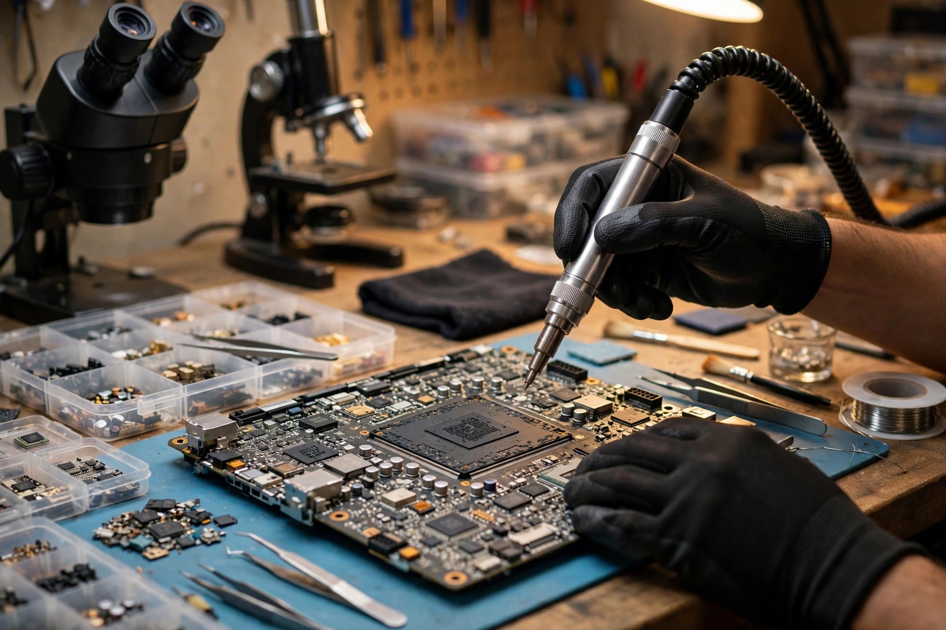
1. Scope First: Only the PCH Chipset Layer
The scope is one situation: a laptop that boots into the system, then loses a whole group of peripherals together, loses them intermittently, slows down and drops connections, or loses a group of peripherals after booting or after waking from sleep, and you want to understand how the chipset layer fails, how outside observation narrows suspicion, how to avoid common misdiagnoses, and what to record before inspection. PCH means Platform Controller Hub. It is not the CPU, not the graphics card, and not memory. It is the I/O hub between the CPU and peripheral devices. When a machine fails to recognise a device, the PCH is only one possible layer, not the only answer.
The following layers appear here only as boundary comparisons and are never expanded into the main subject: the charging layer, the power-sequencing layer, the CPU power layer, the embedded-controller layer, the firmware-corruption layer, the solder-joint layer, the board short-circuit layer, the USB-C power-delivery protocol layer, the memory-instability layer, and the antenna layer. Each appears in section 10 as a single comparison sentence, with no specification or handling detail. Device, driver, system, and BIOS-setting layers appear in the exclusion steps, because the purpose of exclusion is to separate which layer failed first, not to call every recognition failure a chipset failure.
The hard boundary comes first, because the whole value of this approach rests on it. At reader level, only outside observation and recording are in scope: swapping ports, cables, devices, and computers, reading Device Manager and System Information, matching Event Viewer entries by time, and keeping a symptom log. Internal condition is always left to inspection. Never open the machine yourself, remove a base cover or screen, unplug an internal cable, inspect or replace a chip yourself, measure a board, reflow solder, change firmware settings, or rewrite firmware with an unofficial method. Finding an answer from inside the machine is outside reader-level observation.
The safety line also comes first. If you notice a burning smell, abnormal heat, a swollen battery, smoke, sparks, a melted port, or liquid getting inside, stop using the machine at once and send it for inspection. Do not keep booting it to test, and do not keep plugging and unplugging devices to prove a point. The data line matters just as much: if an internal hard drive or SSD suddenly disappears, the first step is always to stop. Do not repeatedly reinstall the system or format anything. Think about backup order and inspection order first.
2. What the PCH Is: From Northbridge and Southbridge to One Chipset
The old architecture used two chips: a northbridge for memory and display paths, and a southbridge for USB, SATA, audio, firmware, and other slower I/O. From the Intel 5 series onward, northbridge functions moved into the CPU, and the remaining work was concentrated into one PCH. Intel describes PCH functions as including ACPI power-management logic, PCIe, a built-in SATA host controller, a USB xHCI host controller, DMI, SPI, eSPI, GPIO, SMBus, audio, and Serial I/O. In other words, the PCH is not one controller. It is a set of controllers sharing one chip, one upstream link, and one set of clock and power domains.
Modern laptops have two physical forms, and they must not be confused. A discrete PCH is a separate chipset chip on the board, connected to the CPU through DMI. An on-package PCH is packaged together with the CPU in the same package, connected through OPI. The difference matters in practice: the layering logic and the handling options for the two forms are completely different, and replacing the PCH fixes it is not a general conclusion. Handling depends on that model design and is left to inspection. Southbridge is only the old name; modern Intel documents use PCH throughout, and PCH is used throughout, so readers do not mistake two names for two chips. AMD platforms also have an equivalent single-chipset role, formerly called Fusion Controller Hub, but AMD I/O division cannot be swapped with Intel division. Intel PCH is the main architecture, and the Intel controller list is not a general list for AMD machines.
| Layer | Responsibility | Boundary the reader should keep |
|---|---|---|
| Processor | Compute cores, memory controller, high-speed PCIe for display, some direct I/O, depending on platform | Not all PCIe belongs to the PCH; display high-speed lanes generally do not pass through the PCH |
| PCH | Remaining I/O: USB, SATA, PCH PCIe, GbE, audio, Serial I/O, SMBus, GPIO, RTC and clocks, SPI and eSPI firmware interfaces, power-management logic | PCH PCIe is PCH PCIe, a different path from CPU-direct PCIe |
| Embedded controller | Connected to the PCH through eSPI, handling keyboard, fan, and power-button embedded control | eSPI is the interface between the PCH and the embedded controller; a fault in the controller itself is another layer |
| Firmware flash chip | Connected through SPI, holding the platform firmware image, including PCH soft-strap settings | Damage to the flash chip itself and damage to the PCH itself are two layers and must not be confused |
3. Upstream Links and Lane Allocation: DMI, OPI, and Flexible I/O
The high-speed link between a discrete PCH and the processor is called DMI. The link inside the package for an on-package PCH is called OPI. All I/O through the PCH must finally travel upstream to the CPU through DMI or OPI, so if the upstream link itself fails, the affected range is all PCH I/O, not one device. The link layer also has signal-integrity requirements, including lane reversal, polarity inversion, clock requests, reference clocks, and reset signals. A link-layer fault can appear as intermittent disconnection, throttling, or devices appearing and disappearing, rather than instant total death.
DMI width varies by SKU, and any number here must be tied to a generation and SKU, never treated as a general number for all laptops. The purpose of the table below is only one thing: to prove that port counts and lane counts depend on the SKU. The actual configuration is decided by the laptop maker, which may leave lanes unused and may assign lanes to different interfaces. The device list shown in Device Manager is the actual configuration of that machine.
| Generation and SKU example | Upstream link | SATA ceiling example | PCIe ceiling example | USB 2.0 total example |
|---|---|---|---|---|
| 800 series H810 | DMI Gen 4 x4 | Up to 4 | PCIe Gen4 up to 8 lanes | 10 |
| 800 series Z890 | DMI Gen 4 x8 | Up to 8 | PCIe Gen4 up to 24 lanes | 14 |
| 600 series H610 | DMI x4 | Up to 4 | PCIe Gen3 up to 8 lanes | Depends on SKU |
| 600 series Z690 | DMI x8 | Up to 8 | PCIe Gen3 up to 16 lanes, Gen4 up to 12 lanes | Depends on SKU |
| 500 series mobile UP3 | OPI x8 | Up to 2 | PCIe Gen3 up to 12 lanes, up to 6 root ports | Depends on SKU |
| 500 series mobile UP4 | OPI x8 | 0 | PCIe Gen3 up to 10 lanes, up to 5 root ports | Depends on SKU |
Flexible I/O is another key concept. Intel high-speed I/O lanes can be configured as GbE, PCIe, xHCI USB, or AHCI SATA. The 800 series lists 42 flexible high-speed lanes, and the 600 series also has flexible lane configuration, with ceilings varying by SKU. The configuration is static: it is selected by soft straps, and the platform designer is responsible for configuring it correctly. When configurations conflict, hardware behaviour is undefined. For readers, this concept has three meanings. First, the same physical slot recognising different devices is not necessarily a fault; for a dual-mode slot, which device type is recognised depends on the static configuration and the inserted device type, not a setting users can change at will in the system. Second, a fault in one high-speed lane can affect only the interface type that lane was configured as, without affecting other lanes, so one dead position with other positions still working can be a lane-level issue, not necessarily a whole-PCH death. Third, a wrong soft-strap setting or a mismatched firmware image can look like a hardware fault on the surface, but soft-strap settings are not user-level settings, and readers must not change them.
4. PCH Controllers, One by One
Each controller below follows the same order: what it does, what the user sees, how it conceptually behaves when faulty, the layer most easily confused with it, and the reader-level comparison. Each controller carries the reservation that a symptom does not necessarily mean the PCH is faulty, and no single symptom amounts to a conviction.
For USB, the PCH provides a USB 3.2 xHCI host controller and a dual-role xDCI device-side controller. The xHCI handles the host side for all USB ports, while xDCI is a device-mode role that everyday users rarely see directly. Speed grades depend on generation: the 800 series xHCI supports USB 3.2 Gen 2x2, while mobile on-package PCH parts list Gen 2x1. Every speed claim is tied to a generation; the highest rate is not the speed of every PCH USB port. What users see is the USB host controller, root hub, and USB devices under Universal Serial Bus controllers in Device Manager. Conceptually, an xHCI-layer fault can appear as several USB ports under the same controller failing to recognise devices together, devices repeatedly connecting and disconnecting, transfers breaking midway, or a device appearing only at USB 2.0 speed while high-speed mode fails. The most easily confused layers are an external hub, a USB cable, the device itself, USB selective-suspend power settings, driver problems, and wear on a single interface, all of which can mimic xHCI symptoms and must be narrowed with the four-swap comparison in section 9. A special reminder: some USB-C ports on a laptop may come directly from the CPU or from a separate controller, and do not necessarily pass through PCH xHCI, so a faulty USB-C port with other USB-A ports normal cannot be blamed directly on PCH xHCI, and the reverse also holds. Check the maker specification first for which port takes which path, and never assume every USB port is PCH.
USB 2.0 and USB 3.x signal paths differ. Inside one USB socket, the high-speed differential pairs and the older signal lines are separate physical paths, so a USB 2.0 device being recognised while a USB 3.x device is not, or the reverse, can be a single signal-path layer rather than a dead host controller. Intel errata also prove that a controller layer can show abnormal behaviour on one port: the 800 series Specification Update records that, under a specific timing when a full-speed device is unplugged, the USB 2.0 function of that port can become temporarily unresponsive until the host controller resets. This example shows that a port temporarily failing to recognise a device does not necessarily mean permanent hardware damage, but it also shows that errata apply only to the listed stepping and cannot be generalised to all PCH parts.
For SATA, the PCH has a built-in SATA host controller supporting SATA 3.2, with a per-port top specification rate of 6 Gb/s. That rate is a specification grade only, not a measured speed on the reader machine. AHCI is the SATA host-controller interface specification set by Intel. In essence it is a data-moving engine between system memory and SATA devices, supporting command queuing, hot-plug, and native SATA power management. What users see is the SATA AHCI controller under IDE ATA/ATAPI controllers in Device Manager, and whether the system lists an internal hard drive at boot. At reader level, only whether it is listed is observed. Conceptually, a SATA-controller-layer fault can appear as an internal SATA hard drive disappearing intermittently, being recognised on some boots and not others, transfer errors increasing midway, or the system failing to boot from the drive while other peripherals stay normal. Note that many modern laptops have moved to PCIe NVMe SSDs, so a missing SSD is only a SATA question for models that still have SATA devices. Not every missing SSD is a SATA problem. The most easily confused layers are the drive itself, a changed SATA mode setting, driver problems, and storage-driver problems after a system update. A special reminder: changing the SATA mode from AHCI to RAID, or the reverse, can leave the system unable to boot. That is a setting-layer problem, not proof that the controller is faulty. At reader level, only record the mode name, and never change modes casually to test. In the SATA layer, not recognised and recognised but unable to read data are two different things. The first points toward detection, link, or controller layers, while the second may point toward the device itself, the file system, or cable signal quality. The two must not be collapsed into one sentence saying the hard drive is faulty.
For PCIe root ports, the PCH provides a set of PCIe root ports, connected upward through the root complex and DMI or OPI to the CPU, and downward to PCIe peripherals such as NVMe SSDs, wireless modules, card readers, or wired-network chips, depending on maker design. The 800 series PCIe specification is Base Specification Revision 5.0, with lane counts varying by SKU from 8 to 24. The 600 series mixes Gen3 and Gen4 depending on SKU, and the 500 series desktop PCH uses Revision 3.0. Root ports are a limited resource: the 700 series documents list up to 16 PCIe root ports, and enabling GbE reduces the usable root-port ceiling by one. That example only explains that the maker must allocate ports. What users see is PCIe root ports and PCI devices under System devices in Device Manager. Conceptually, a PCH PCIe-layer fault can appear as a whole class of devices under PCH PCIe disappearing together, a device showing a warning mark or an error code, a device appearing on some restarts and disappearing on others, or transfer speed falling abnormally. This section speaks only in concepts; no specific throttling figure serves as a diagnostic threshold. The most easily confused layer is a CPU-direct PCIe path fault, which can look like a PCH PCIe problem. The key distinction is whether the missing device hangs off the CPU or the PCH, judged against the maker block diagram and the Device Manager hierarchy display. At reader level, only record the hierarchy relationship, and never infer a lane number from it.
For audio, the PCH provides an Intel HD Audio controller and Intel Smart Sound Technology, supporting I2S, MIPI SoundWire, and DMIC interfaces. What users see is audio devices under Sound, video and game controllers in Device Manager, and SST-related devices under System devices. Conceptually, a PCH audio-layer fault can appear as the built-in speaker plus headphone jack plus built-in microphone disappearing as a group, because they share the same audio controller and codec path, while a USB headset or Bluetooth headset still works, because those take USB or Bluetooth paths rather than PCH HD Audio. This contrast, built-in audio dead as a group while USB audio works, is a useful reader-level clue, but it is still not a diagnosis, since audio drivers, codec settings, and system volume settings can mimic it. The most easily confused layers are the speaker itself, the headphone jack, audio drivers, system audio settings, and application exclusive mode, which must first be excluded with a USB or Bluetooth audio comparison. Controller not recognised and speaker silent are two separate layers; the audio controller and the speaker are not the same thing.
For wired networking and wireless interfaces, the PCH provides a built-in GbE controller, connected through a data link to an Ethernet connection chip, and a CNVi link that integrates part of wireless-module function into the PCH while the rest stays on the external wireless module. What users see is Ethernet and wireless devices under Network adapters in Device Manager. Conceptually, a GbE-layer fault can appear as a wired network port failing as a group, links dropping intermittently, or speed behaving abnormally. A CNVi-layer fault can appear as a wireless device disappearing from Device Manager, rather than merely weak signal. Weak signal, failure to find a particular Wi-Fi network, or slow speed look more like antenna, radio, or router layers, and must not be treated directly as CNVi failure. The most easily confused layers are the network cable, the router, drivers, power-management settings that put the network card to sleep, flight mode, and BIOS settings that switch network devices off. Comparison must start with swapping cables, swapping router ports, and checking whether Device Manager shows a device at all, rather than only checking whether the network connects. A missing wireless device does not equal CNVi failure. A missing wireless device can also be a driver, setting, module, or lane-allocation problem, so record the two different patterns, missing versus signal problem, separately.
For Serial I/O, the PCH provides I2C, UART, and GSPI controllers, plus newer-generation I3C controllers, and a touch host controller for touch interfaces. These controllers handle low-speed peripherals other than the keyboard: sensors, parts of touchpad or touchscreen interfaces, and embedded-device communication, depending on maker design. What users see is I2C and Serial I/O devices under System devices or Human Interface Devices in Device Manager, and the appearance state of the touchpad or touchscreen. Conceptually, a Serial I/O-layer fault can appear as a touchpad, touchscreen, or sensors failing as a group or intermittently, while a USB mouse still works, because a USB mouse takes the xHCI path. This contrast helps separate the USB layer from the Serial I/O layer, but it is still not a diagnosis, since drivers, settings, and the touchpad itself can mimic it. The most easily confused layers are touchpad drivers, system touch settings, a touchpad on-off key, function-key switches on some models, and interference from an external mouse. First record whether an external USB mouse works normally as the comparison. Not every touchpad problem is a PCH Serial I/O problem. The touchpad itself, its cable, and its driver are common other layers.
For firmware and low-speed channels, the PCH provides LPC or eSPI interfaces, connecting the embedded controller, TPM, and trusted-platform devices, plus an SPI interface connecting firmware flash memory. The 800 series documents state that SPI0 supports two flash devices, with a third chip-select dedicated to a TPM on SPI, and require a flash device with a valid descriptor on the first SPI0 chip-select. Ordinary users will not see an eSPI controller name directly in Device Manager. Reader-level clues are indirect: whether boot settings can be saved, whether TPM and device-encryption status display normally, and whether embedded devices list normally. eSPI and LPC reader-level clues are indirect, and readers must not use any tool to read eSPI signals. Conceptually, a fault in this layer can appear as boot settings repeatedly lost, TPM-related functions behaving abnormally, or embedded devices disappearing intermittently, but these symptoms can also be setting, driver, or firmware-version problems, and must be read together with section 7 on firmware interfaces, never convicted on one symptom alone. Internal signals, timing, chip-selects, and descriptor structures for LPC, eSPI, and SPI are only concept nouns here. Measurement, wiring, and rewriting methods are all outside reader level.
For SMBus, GPIO, and the sensor hub, the PCH provides an SMBus controller supporting SMBus Specification Version 2.0, GPIO for maker-designed switches, indicators, and control signals, and an integrated sensor hub that gathers sensor data. What users see is the SMBus controller and GPIO-related devices under System devices, and the appearance state of sensors in the system. Conceptually, a fault in this layer can appear as sensors failing as a group or system-management information reading abnormally or missing, but reader-level monitoring software readings can themselves be affected by drivers and settings, so never treat a monitoring reading directly as a hardware measurement. SMBus has a conceptual link to charging and battery communication, but only the PCH SMBus controller role is within scope. The charging layer and battery layer themselves are not expanded into main subjects.
| Controller | Where users see it | Conceptual group-failure behaviour | Most easily confused other layers |
|---|---|---|---|
| USB xHCI | Universal Serial Bus controllers | Several USB ports under one controller failing to recognise devices together, repeated disconnection | External hub, cable, device, power-saving settings, driver, single-interface wear |
| SATA AHCI | IDE ATA/ATAPI controllers | Internal SATA device disappearing intermittently, recognised on some boots only | Drive itself, SATA mode setting, driver, system update |
| PCH PCIe root ports | Root ports and PCI devices under System devices | One class of devices under PCH PCIe disappearing as a group, warning marks | CPU-direct PCIe path, driver, setting |
| HD Audio and SST | Sound, video and game controllers | Built-in speaker plus headphone jack plus microphone disappearing as a group, USB audio normal | Speaker itself, headphone jack, driver, audio setting |
| GbE and CNVi | Network adapters | Wired port failing as a group, or wireless device disappearing from Device Manager | Cable, router, driver, power-saving sleep, setting switch-off |
| Serial I/O and touch | System devices, Human Interface Devices | Touchpad, touchscreen, sensors failing as a group, USB mouse normal | Touchpad itself, driver, touch setting, function-key switch |
| LPC, eSPI, SPI | Indirect clues mainly; Device Manager does not show the controller name directly | Boot settings repeatedly lost, TPM functions abnormal, embedded devices disappearing intermittently | Setting, driver, firmware version |
| SMBus, GPIO, sensor hub | System devices | Sensors failing as a group, system-management information missing | Driver, setting, monitoring-software reading error itself |
5. Clocks, Real-Time Clock, and Power-Management Logic
The PCH has a built-in integrated clock controller that generates and distributes system clocks. The 800 series system-clock section lists clock-request signals, crystal inputs and outputs, and clock outputs. The real-time clock is also a PCH function, handling time recording before boot and wake events. Clocks are a shared precondition for all high-speed interfaces: USB, SATA, PCIe, and DMI all need correct reference clocks before link training and data transfer can happen. If a clock source or clock distribution fails, the affected range can span several controllers, looking on the surface like the whole PCH has died, while the actual layer is the clock layer. No clock-frequency threshold, clock-jitter figure, or figure for how much clock deviation breaks a link applies generally, because those figures vary by platform and signal.
The PCH provides ACPI power-management logic support, coordinating system power states. The power-management controller and CSME are firmware engines inside the PCH that take part in power-state transitions and platform management. Power-management-layer symptoms often appear only at a transition, for example sleeping normally but failing to wake, or failing to boot again after shutdown. That pattern, failing only at the moment of transition, is a different clue from a persistent fault where a device is never recognised. The 500 series Specification Update records CSME and power-management-controller power-state transition errata as fixed, which shows that power-state transition is itself a separate fault surface and cannot be simplified to the PCH being faulty.
The PCH does not have a single power domain. It has a standby domain that stays powered in standby, handling wake, the real-time clock, and part of power-management logic, and a main domain powered only in the main working state, handling high-speed I/O controllers. The two domains differ in supply source, enable timing, and failure behaviour. If the standby domain is normal and the main domain is abnormal, symptoms can be a response to power, a light when the power button is pressed, but failure to enter the system or total I/O loss. If the standby domain itself is abnormal, symptoms can appear earlier, such as no response to wake events or abnormal real-time-clock state. The two cannot be separated by a single light signal. No general PCH power-rail voltage figure, current figure, or table of what each rail should read applies, because those figures vary by platform, SKU, and power design, and one wrong figure would mislead the whole layering. PCH power domains must be established in order, and reset signals must be released at the correct timing, before initialisation can complete. That timing layer belongs to the power-sequencing topic, so only the precondition stands: PCH initialisation needs correct power domains and reset timing; no timing table is within reader-level scope.
Inside the PCH, high-speed peripherals travel upstream to the CPU through DMI or OPI, while low-speed peripherals take another low-speed control path. This division explains why a whole group of high-speed peripherals slowing down or disappearing, and a low-speed function behaving abnormally, can be different layers rather than one story. Clocks and power domains are a third invisible path: different controllers can belong to different power domains, so a fault in one domain can make the controllers in that domain behave abnormally together, while controllers in other domains stay normal. At reader level, only which group fails together can be observed. Which domain failed cannot be measured from outside.
6. Why It Fails: Eight Mechanism Lines, Each Independent, None a Substitute for Another
The first line is power-domain abnormality. PCH power domains are supplied by board power circuits. Abnormal output from a supply circuit, for example a rail in one domain falling outside its working range, excessive ripple, or an abnormal enable signal, can leave the corresponding PCH function unit unable to initialise or resetting intermittently, while functions in other domains stay normal. That is why partly working I/O with partly dead I/O can be a power-domain layer, not necessarily a PCH-body layer. Another form is domains dragging each other down: an abnormal load in one domain can pull down a shared rail and make several controllers abnormal together, looking on the surface like the whole PCH has died, while the actual layer is load or supply, to be separated against that model circuit diagram. When talking about supply, name which domain, rather than speaking generally about supply. General talk about a supply problem makes readers think swapping the power adapter fixes it, while a PCH power-domain problem and an adapter problem are two layers.
The second line is firmware state and power state locking each other. The 600 series errata record that, after a real-time-clock reset and within a specific firmware-version range, a PCH debug subsystem can enter an unsupported state, and the system may stall when leaving the mechanical off state, needing the system firmware image to be written again before recovery. This example proves that firmware state plus power state can lock each other, rather than a single permanent hardware fault. Another class of examples is the 500 series Specification Update, which records CSME and power-management-controller power-state transition, deep-sleep entry conversion, and deep-sleep entry with GbE enabled errata, some fixed and some listed as unfixed. Any citation must state which stepping, which state, and what the fix status is, and one erratum must never be treated as a problem in all PCH parts. Intermittent faults tied to power-state transitions, for example appearing only after one sleep or only after one complete power removal, cannot be lumped together as the PCH being burnt. The difference between a locked state and permanent damage lies in whether recovery follows a state reset, and whether the fault only recurs on a specific transition path.
The third line is clock abnormality. High-speed interfaces need accurate reference clocks before link training. An abnormal clock source, clock-distribution path, clock-request signal, or internal clock gating can leave one or several controllers unable to establish links. A verified clock-gating example is the 600 series errata record that, when all SATA ports are idle or disabled, a SATA enclosure-management LED message may fail to be sent because of an internal clock-gating problem, making the LED state wrong. The impact in that example is only the LED state, not data transfer itself, and citation must not inflate it into clock gating killing SATA. The distinguishing feature of the clock layer is qualitative: clock problems usually affect several interfaces sharing one clock source, and symptoms can be intermittent, such as links working sometimes, throttling, or succeeding only after retries, rather than one port permanently dead. Clock-layer and controller-layer symptoms can mimic each other, so final layering must rest on that model design.
The fourth line is heat. The PCH itself has a thermal-sensing function. Rising temperature inside the machine shifts chip internal characteristics, narrows signal margins, and makes high-speed links more likely to retry errors. Sustained high temperature also speeds ageing of nearby passive components and solder joints. An important distinction is that PCH heat and CPU heat are two different things. A normal CPU temperature reading does not mean a normal PCH temperature, because they are different chips on different cooling paths, and a CPU temperature reading is not PCH temperature evidence. In symptom pattern terms, heat-related faults usually follow a cold-normal, hot-faulty, cool-again-normal time pattern, or a cumulative pattern of failing only after a period under heavy load. But failing only when hot can also be other heat-sensitive layers, so a time pattern alone cannot be used to declare the PCH body overheated. No PCH temperature threshold, thermal-shutdown temperature, or cooling-design figure applies generally, because they vary by product.
The fifth line is humidity and corrosion. The mechanism chain is qualitative, with each step independent, and must not be treated as inevitable causation: in a humid environment, condensation or long-term dampness inside the machine, then corrosion products on metal contacts, solder joints, and trace surfaces, then rising contact resistance, falling insulation resistance, and even unexpected leakage paths, then falling high-speed signal integrity, inaccurate sensing signals, and intermittent contact. A second-level source comparison notes that white or green residue from liquid damage is one common cause of complex faults and can bridge traces into short circuits. That statement only supports the concept that corrosion can cause short circuits or leakage, not evidence that Hong Kong humidity necessarily causes PCH faults. Corrosion is a slow process. Dampness at one moment may show no symptom at all, with intermittent symptoms only gradually appearing as corrosion products accumulate, and only later becoming persistent. So a machine that got wet months ago and only fails now cannot have the corrosion layer excluded by the time gap alone, and cannot have it declared as the layer by the time gap alone either.
The sixth line is electrostatic discharge. A GIGABYTE FAQ for old-generation southbridge ICH4 and ICH5 states that a southbridge chip could be damaged when connecting a USB device, with three possible causes: static accumulated on a person transferring to the southbridge when connecting a USB device, the connected USB device itself having no electrostatic protection, and a front-panel USB port not being properly grounded. That example belongs to the old ICH generation and cannot be applied directly to all modern PCH USB faults. Modern PCH I/O design, protection levels, and processes differ, and any citation must note the generation limit. In mechanism terms, electrostatic discharge is a nanosecond-scale high-voltage transient entering through a connector shell or signal pin, capable of directly damaging USB transceiver structures. Damage can be immediately catastrophic, with that channel dead at once, or latent, with internal structure damaged but still operating at the time, failing only gradually later. High-speed ports usually have added electrostatic-protection components, with design points including parasitic capacitance, clamping voltage, channel coverage, and grounding path. Failure of a protection component itself, incomplete protection coverage, or too-high clamping voltage can let electrostatic energy strike PCH I/O units directly. Electrostatic faults usually follow a plug event, for example a port dying after a particular device was plugged in, but appearing after plugging does not mean that device necessarily has a problem, and does not mean static is necessarily the cause, because plugging also involves mechanical contact, power transients, and driver enumeration. Latent electrostatic damage is the hardest class to separate: testing normal at the time, then failing intermittently later. Normal testing at the time does not prove static is unrelated.
Need a laptop repair expert?
Free diagnosis · Transparent pricing · No fix, no fee · 180-day warranty
The seventh line is the firmware-interface layer. Very early in boot, before BIOS or software intervention, the PCH reads soft-strap data through the SPI device to configure specific PCH and processor functions, with strap data managed by platform firmware-image tools. The consequence of a configuration conflict is that the platform designer is responsible for configuring lane multiplexing and soft straps correctly, without conflicts. When a conflict exists, hardware behaviour is undefined, and undefined means symptoms can vary wildly, so no symptom can be used to work backward to which strap is wrong. A firmware-image version mismatched with PCH stepping and platform design can look on the surface like some I/O disappearing for no reason or some functions failing to enable, but that layer belongs to firmware or platform design, not to a problem a user can fix in system settings. Readers must not change straps, write firmware, or use unofficial tools to flash firmware.
The eighth line is ageing and mechanical stress. Long-term thermal cycling, from powering on and off and from hot and cold load changes, stresses solder joints and contacts through expansion and contraction. Commuting, backpack squeezing, opening and closing, and force on the body can bend the board slightly. Both can shift contact condition gradually, from fully normal to intermittent contact, then to persistent poor contact. For the PCH layer, the meaning is that the PCH body may be undamaged, while changes in its connection to the board or in nearby signal-path contact can still appear as PCH I/O abnormality. That layer belongs to solder-joint topics, so only the concept stands: connection-layer drift can mimic a PCH-body fault; solder mechanisms are outside reader-level scope. How many openings or how many years cause failure cannot be converted into a life figure. Thermal-cycle counts, stress magnitudes, and material properties vary by machine, and any conversion would be invented.
7. Firmware Interfaces: Management Engine, CSME, Flash Regions, BIOS Settings, and Chipset INF
Intel PCH documents state that, in descriptor mode, SPI flash is divided into regions: region 0 for the flash descriptor, region 1 for BIOS, region 2 for CSME, region 3 for GbE, region 8 for the embedded controller, and region 10 for the Silicon Security Engine. Only four kinds of controllers may access these regions: the main processor running BIOS code, built-in GbE, CSME, and the embedded controller. This division explains why a firmware problem is not a single-file problem: the BIOS region, CSME region, descriptor, and GbE region each have their own job, and an abnormality in one region can make the corresponding group of peripherals behave abnormally while other regions stay normal. At reader level, these regions cannot and should not be read or modified by users. The division concept is the limit; reading, backup, rewriting, or clearing CSME methods must not be attempted by readers. The descriptor role is only described as data used at boot to divide regions and access rights, without descriptor structure or modification methods.
CSME is a small low-power subsystem built into Intel chipset platforms, handling security and management functions. CSME firmware lives in the CSME region of SPI flash and runs early in boot. Abnormal CSME version or state can make the system behave abnormally, but readers cannot judge CSME state from outside appearance. The management-engine interface device state under System devices in Device Manager is only one indirect clue, not a diagnosis of CSME itself. Clearing CSME, disabling the management engine, or flashing CSME methods must not be attempted by readers, and methods for exploiting CSME security issues are likewise excluded. Security issues appear only as one background sentence: Intel has published a security white paper and mitigation measures for CSME, and maker firmware updates are the official handling path. Vulnerability detail is not part of the background. Reader-level comparison is limited to recording whether the management-engine interface device appears in Device Manager, whether it shows a warning mark, and the driver provider and version, judged against the maker driver page, plus whether a maker firmware update happened before the problem appeared. Hand those records to inspection, and never judge CSME faulty yourself.
For the BIOS-setting layer, which settings affect PCH peripherals is explained only by direction of effect, never as instructions to change settings casually. Every item in the table below carries the reminder to record, not to change settings casually. Any suggestion to change a setting must rest on maker documents or inspection advice, with a reminder to record the original setting and back up data first.
| BIOS setting category, names vary by maker interface | How it conceptually affects PCH peripherals | What readers may do at reader level |
|---|---|---|
| USB controller switch, xHCI mode, Legacy USB support | Switching a USB controller off or changing mode can make a group of USB ports unrecognised or run only in low-speed mode | Record the current setting name and state, and never toggle items by feel to test; after a setting is reset, first compare what changed before and after the update or power loss |
| SATA mode, SATA controller switch | Changing mode or switching a controller off can make SATA devices disappear or leave the system unable to boot | Record the current mode name; never change mode without backup and without understanding the consequence |
| PCIe settings, ASPM power saving, root-port switches | Switching a root port off or tightening power-saving settings can make devices on that port disappear or behave intermittently | Record whether a related setting was changed before the device disappeared; for power-saving intermittent problems, first compare power plans |
| HD Audio and SST switches, built-in device switches | Switching an audio controller off can make built-in audio disappear as a group, while USB audio still works | Record the switch state; use USB audio comparison to separate a controller switch from a speaker problem |
| Built-in network or wireless switches, CNVi-related switches | Switching a network device off can make wired or wireless devices disappear from Device Manager | Record the switch state; missing device and signal problem are two different things |
| TPM and security switches, boot order | Abnormal TPM state can affect device encryption and boot verification functions | Record how TPM displays in the system, and never clear TPM or change security settings casually to test |
| Maker firmware version | Firmware version can affect peripheral initialisation, compatibility, and the fixed state of known problems | Record the version number, update date, and whether symptoms changed before and after the update; updates only through the path the maker provides for that exact model |
At the boundary between driver layer and firmware layer sits chipset INF. Intel chipset device software installs Windows INF files. An INF is a text file that gives the operating system hardware information, so Device Manager can display the correct hardware name. Dell driver documentation also states plainly that INF files provide hardware information and let Device Manager display correct names, and that chipset software does not install drivers for USB, nor can it solve USB port problems. This distinction matters greatly: many users think installing chipset drivers equals fixing USB or SATA, but INF only renames and identifies. It is not a functional driver for USB or SATA. Device Manager changing from unknown device to a correct name does not mean that controller function has recovered. Conversely, a correct device name with abnormal function does not mean INF is faulty. Reader-level comparison is to record three items: whether the device name is unknown or correct, whether a warning mark appears, and whether the driver provider is Microsoft or the maker. Hand those to inspection. Driver installation only ever uses the laptop maker driver page for that exact model, never a third-party driver-aggregation tool.
8. Which Layer Failed: Single Channel Versus Multiple Channels Failing Together
The PCH is internally layered: single ports or lanes, then single controllers, then shared power or clock domains, then the upstream link, then whole-PCH initialisation. As the affected range widens from narrow to broad, the suspected layer rises accordingly. This principle is not a diagnostic rule, but a suspicion ranking: a broad range does not necessarily mean the upper layer is definitely faulty, since a shared power-domain fault can mimic an upper-layer fault, and a narrow range does not necessarily mean the lower layer is definitely faulty, since a single-port logic fault in an upper controller can affect only one port. Layering uses rising or falling suspicion language; words such as proves or definitely do not establish a conclusion for any layer. Conclusions can only be judged at inspection level against that model information.
| Affected range | Example symptoms, qualitative | Layer whose suspicion rises, direction only | Why it cannot be concluded directly |
|---|---|---|---|
| Single port or single lane | One USB port fails to recognise a device while other USB ports work; one SATA position fails to recognise a drive while other positions work | That port physical layer, connector, cable, that lane configuration | A single port can also be that port controller single-port logic abnormality, or that lane HSIO configuration problem |
| All ports of one controller | All devices of one class fail together, for example all USB ports fail to recognise devices, but SATA and networking work | That controller itself, for example xHCI, that controller power or clock domain, that controller driver or setting | Driver layer, BIOS setting switching that controller off, or power-management wake failure can all mimic a dead controller |
| Several controllers abnormal together | USB plus SATA plus audio and other device classes fail together, but booting and CPU operation are broadly normal | Shared power domain, shared clock domain, PCH internal interconnect, partly abnormal upstream link | Shared-layer abnormality and upstream-link abnormality look similar on the surface and need that model design to separate; a system layer can also affect several device classes at once |
| All PCH I/O abnormal together | All peripherals through the PCH disappear or cannot be enumerated together, but CPU-direct devices, for example display, still show a picture | Upstream link, PCH initialisation, PCH main power domain | Normal CPU-direct devices only prove the CPU and display path are broadly normal, not that the PCH body is definitely damaged; a firmware-interface layer can also cause a similar total loss |
| Boot or wake layer abnormal | Cannot boot, stuck in the boot process, all peripherals lost after waking, cannot boot again after shutdown | PCH initialisation, power-state transition, RTC and power-management controller, firmware-interface layer | Boot-layer abnormality involves embedded controller, power sequencing, firmware, and other layers; the PCH is only one of them, and boot symptoms alone cannot be used to declare a PCH fault |
For DMI and OPI distinction, four principles apply. First, CPU-direct normal plus a whole PCH group abnormal raises suspicion toward the PCH layer or the DMI or OPI layer, but driver, setting, and shared external-device layers must still be excluded. Second, CPU-direct abnormal plus PCH normal looks more like a CPU layer or CPU-direct path problem, and is not a PCH fault. Third, both abnormal together looks more like a whole-system layer or multiple problems, and must not be explained by the PCH alone. Fourth, only one PCH peripheral abnormal with other PCH peripherals normal looks more like a single device, single interface, or single controller problem, and must not be upgraded directly to a whole-PCH fault. The Device Manager hierarchy display can help users record which device sits under which root port, but hierarchy display does not equal lane numbers. Readers must not infer lanes or chip positions from hierarchy numbers.
Bandwidth bottleneck and link failure are two concepts that must not be confused. A bandwidth bottleneck is a normal design limit: when several PCH high-speed peripherals transmit at full speed at once, total demand may exceed the DMI or OPI upstream bandwidth ceiling, appearing as a whole group of peripherals slowing together, while devices still appear, with no error codes, and normal behaviour returning at idle. That is a design limit, not a fault. Slow does not equal faulty. Link failure is a suspected fault direction: PCH peripherals disappearing as a group, error codes, intermittent disconnection, and appearing on some restarts but not others, with no clear relationship to load, disappearing even at idle. Only that pattern is worth suspecting for a link or PCH layer, and it still needs inspection confirmation. Reader-level comparison records slow versus missing as step one, idle versus loaded as step two, and whether CPU-direct parts are affected at the same time as step three. Only with all three steps complete can a suspicion direction be stated. Missing any step means no conclusion should be drawn. On-package PCH models are harder to separate: with the PCH and CPU in the same package, readers cannot tell from outside appearance which die is faulty, and the options for PCH handling versus CPU or board handling are conceptually tied together, because package and board design vary by model. Reader-level comparison on on-package models can only say that PCH-connected peripherals fail as a group; it cannot say that the PCH die is definitely faulty or that the CPU is definitely faulty.
9. Symptom Patterns and Layer-by-Layer Exclusion: From Outside In, From Soft to Hard
Symptom patterns must first be divided by how many devices are affected, then by when the fault appears, then by how it changes after restart or sleep, then by whether CPU-direct parts are affected. Only with all four dimensions complete can a suspicion direction be stated. Missing any dimension means only that information is insufficient to separate layers.
| Pattern | Affected range | Time character | PCH suspicion change, direction only, not diagnosis | Next comparison |
|---|---|---|---|---|
| Single-port failure | 1 port or 1 device | Persistent or intermittent | Lower | Swap port, cable, device |
| Whole-group failure | Whole group under one controller | Persistent or missing from boot | Rises, driver, setting, and hub must be excluded | Complete affected list plus unaffected list |
| Intermittent failure | Single group or cross-group | Sometimes normal, sometimes missing | Cannot be convicted on intermittency alone, look at the pattern | Symptom log plus wake and restart comparison |
| Missing from boot | Single or grouped devices | Missing on every boot | Rises, separate BIOS present versus Windows present | BIOS list plus Device Manager plus System Information, three layers of records |
| Cross-group failure | Different controllers | Persistent or intermittent | Higher, first confirm CPU-direct state | Affected versus unaffected comparison table plus DMI and OPI distinction |
| Slower but not missing | Whole group of high-speed peripherals | Slow under load, normal at idle | Looks more like a bandwidth bottleneck, not link failure | Record load versus idle comparison, do not treat it as a fault |
A whole-group failure example is all USB-A ports failing to recognise devices together, while a USB-C port, which may be CPU-direct depending on model, works normally; all SATA devices disappearing together; or the built-in speaker plus headphone jack plus built-in microphone disappearing together. The suspicion direction is that suspicion toward one PCH controller layer rises, because the symptom matches a shared-controller pattern, but driver, setting, shared external hub, and power-management layers must still be excluded. Reader-level comparison is to record the complete affected list, which ports and which device classes, and the unaffected list, which ports still work normally. Handing both lists to inspection is far more useful than only saying USB is completely broken. Whole-group failure does not equal a faulty PCH. Whole-group failure can also be chipset INF missing, BIOS switching a controller off, a shared hub fault, or a driver crash.
An intermittent failure example is a wireless module unrecognised on three out of ten boots, a USB device disconnecting while in use and working again after replugging, or a group of peripherals lost after waking from sleep and restored after restart. An intermittent pattern by itself does not point to one layer. PCH, lane, power-management, driver, and device layers can all cause intermittency. The value of an intermittent pattern lies in recording the pattern, not in intermittency equalling any particular layer. Common intermittent traps include USB selective suspend, PCIe ASPM power saving, network-card power-saving sleep, and instability after a driver update. These power-saving layers especially like to appear as failing after wake and normal after restart, so a wake-after failure is not directly a PCH fault.
A missing-from-boot example is a PCH device absent from Device Manager on every boot, and absent from the BIOS or UEFI device list. The suspicion direction is that missing from boot is more worth suspecting for controller, lane, setting, or firmware-initialisation layers than a device that drops while in use, because the device never passed the enumeration stage. But BIOS switch-off, missing drivers, and device faults must still be excluded. Reader-level comparison is to record three layers of appearance state: whether the BIOS or UEFI list shows it, whether Device Manager shows it, and whether System Information shows it. Only when all three are absent is a deeper layer worth suspecting. If BIOS shows it but Windows does not, the pattern leans more toward driver or system layers. Absence from BIOS does not equal a faulty PCH. BIOS list display varies by maker interface, and some devices are never listed in BIOS lists by design, so maker documents are the standard.
A cross-group failure example is USB plus SATA plus audio plus networking failing together, while CPU-direct display and the main SSD stay normal. The suspicion direction is that cross-group failure is more worth suspecting for a shared upstream layer, shared power or clock domain, or whole-PCH layer than single-group failure, but it can also be a system, firmware, or power whole-system problem, so first confirm whether CPU-direct parts are affected. Reader-level comparison is a simple affected versus unaffected comparison table handed to inspection, never a vague description such as all peripherals on the whole machine are broken. Cross-group failure does not equal the whole board being broken. Handling options for cross-group failure depend on model, parts supply, and quotation, and must not be pre-judged in the symptom section.
Exclusion principles belong at the start of the exclusion section. The order principle is to exclude the easiest-to-change, least-destructive variables first, external devices, cables, drivers, and system settings, then move to harder-to-change variables, BIOS settings and lane comparison, and only last to board-level judgement. Reversing the order, for example suspecting the board at once, misjudges many software or external problems as hardware faults. The single-variable principle is to change only one variable at a time, for example only one device, only one port, or only one setting, and record the result after the change. Changing several variables at once leaves no way to tell which change mattered. The recording principle is that recording trigger conditions is more valuable for layering than recording that something is broken, including which device type, which port, how long after boot, cold or hot machine, plugged in or on battery, after waking or after booting, and whether it appears only after a particular power-state transition. These records are only reader-level observation, not internal inspection steps. The proof-ceiling principle is that reader-level layering can only rank suspicion, never diagnose. No normal test result at any layer proves that layer is definitely faultless, and no abnormal test result at any layer proves that layer is definitely faulty.
The first layer is external devices. Reader-level observation only: swap in a known-good device on the same port, move the same device to another port of the same type, swap a cable, check whether the device itself needs extra power, and note whether the fault only appears after connecting one particular device. What can be excluded is that if symptoms follow the device after swapping devices or ports, meaning whichever port connects that device fails, suspicion tilts toward the device layer. If symptoms follow the port, meaning whichever device connects to that port fails, suspicion tilts toward that port or lane layer. What cannot be proved is that swapping devices and still failing does not mean definitely a PCH problem, since driver, system, BIOS-setting, controller, and power-domain layers are still unexcluded. The first layer is only a starting point, not an endpoint.
| Test | Method, outside operation only | If the result is this | How suspicion changes |
|---|---|---|---|
| Swap port | Same device, same cable, to another port of the same type | Swapping ports fixes it at once | Leans toward the original port, original lane group, or original port setting |
| Swap cable | Same device, same port, another known-good cable | Swapping cables fixes it at once | Leans toward a cable problem, and the PCH should no longer be suspected on that evidence |
| Swap device | Same port, same cable, another known-good device of the same type | Swapping devices fixes it at once | Leans toward the original device itself |
| Swap computer | Plug the suspected device into another computer | The other computer also fails | Leans toward the device itself; the other computer works, leans toward the original machine port, controller, driver, or setting, needing the two views below |
| Swap hub or dock | Remove an external hub or dock, plug directly into a body port | Direct plugging fixes it at once | Leans toward the hub or dock, or its power or driver problem, and the PCH should not be suspected directly |
| Swap power situation | Run the same test plugged in and on battery, observation only, without changing power ceilings | Only fails in one power situation | Leans toward a power-management setting layer, and the power-plan name must be recorded |
| Swap boot situation | Record cold boot, restart, and sleep-wake behaviour separately | Only fails after waking | Leans toward a power-saving or wake layer, and the wake method must be recorded |
The second layer is drivers and the system. Reader-level observation only: note the controller or device state in Device Manager, for example whether a warning mark appears, whether it is not listed at all, or whether it appears intermittently; note whether symptoms began after a particular system update or driver update; and note whether symptoms appear only under a particular power plan or usage pattern. What can be excluded is that if symptoms follow the driver version, for example appearing after a driver update and disappearing after rolling the driver back, suspicion tilts toward the driver layer. If symptoms still recur stably after system-level changes, driver-layer suspicion falls, but cannot fall to zero, because drivers can change load patterns and make hardware gaps appear intermittently. What cannot be proved is that reinstalling the system and still failing does not mean definitely a hardware problem. Reinstalling the system does not change BIOS settings, firmware state, or lane configuration, so reinstalling without effect is not hardware diagnosis evidence. Driver layer and PCH layer mimic each other: a driver error can leave a controller in an abnormal state for a long time, looking like a dead controller, and a PCH controller abnormality can leave a driver unable to enumerate a device normally, looking like a broken driver. The two must be separated by which variable symptoms follow, never judged from one screen alone.
The third layer is BIOS settings. Reader-level observation only: enter the BIOS setting screen, note whether a related controller is set to disabled, whether the SATA mode setting matches the mode at system installation, and whether USB-related settings are switched off. Note whether settings were reset after a power loss, a real-time-clock state change, or a firmware update. What can be excluded is that if a controller is disabled in BIOS settings, its complete absence from the system is expected behaviour, not a fault. If the setting is clearly enabled but the system still does not list it at all, suspicion tilts toward controller, firmware-interface, or power-domain layers. What cannot be proved is that the BIOS setting screen only shows setting values, not hardware state. Enabled does not mean hardware is definitely normal, and disabled does not mean hardware is damaged. Setting and state are two separate concepts. The third layer only reaches the observation level of noting whether a setting is enabled. Readers must not change soft straps, flash firmware, use unofficial tools to change firmware settings, or change any advanced BIOS setting involving voltage, clocks, or lane configuration. All of those belong to non-reader-level risky behaviour and must not be attempted by readers.
The fourth layer is single-lane versus multi-lane comparison, the practical application of section 8. The task is to organise first-to-third-layer results into a comparison table: which ports and device classes fail, which stay normal, and whether failures belong to one controller, one power domain, one clock domain, or span several controllers. A single port failing with other ports of the same type normal concentrates suspicion on that port or lane layer. All ports of one controller failing with other controllers normal concentrates suspicion on that controller, driver, or setting layer. Several controllers failing together tilts suspicion toward shared power-domain, clock-domain, or upstream-link layers. All PCH I/O failing with CPU-direct devices normal tilts suspicion toward upstream-link or initialisation layers. Boot or wake layer failure tilts suspicion toward initialisation, power-state transition, or firmware-interface layers, while keeping embedded-controller, power-sequencing, and firmware possibilities open. A comparison table can only rank suspicion, never diagnose. In particular, several lanes failing together does not mean the PCH body is definitely faulty, because shared power domains, shared clock domains, firmware-interface layers, and system layers can all cause several lanes to fail together.
The fifth layer is the board layer, meaning inspection-level judgement, not reader-level steps. Reaching this layer means the first four layers are complete, symptoms still recur stably, and the range comparison already points toward PCH-related layers. Remaining layering needs that model circuit diagram, service manual, and platform datasheet as its basis, and is judged at inspection level. Layering stops at this point. Board-layer questions are listed as questions only, without methods: is it the PCH body, a PCH power domain, a PCH clock domain, a PCH firmware interface, or a connection or load layer around the PCH; is it the whole PCH, a single controller, or a single lane; is it a persistent fault or an edge or intermittent fault? Observation records a reader can prepare include the symptom comparison table, trigger-condition records, which changes and results came from the first three layers, and data importance. These records can help inspection layer faster, but they cannot replace inspection judgement. At the fifth layer, internal inspection steps, measurement steps, steps involving handling inside the machine, chip-replacement steps, and heating or rework steps are all outside reader level and must not be attempted. Any of those would break the hard boundary.
For Device Manager reading, the public method is to press the Windows key plus R, type devmgmt.msc, and press Enter. Dell official documentation also uses this method to open Device Manager, and notes that problem devices are usually marked with a yellow warning mark, listed under Other devices, and marked as an unknown device. Which nodes to look at, matched to PCH controllers: Universal Serial Bus controllers for xHCI, IDE ATA/ATAPI controllers for SATA, System devices for PCIe root ports, SMBus, GPIO, Serial I/O, and the management-engine interface, Sound, video and game controllers for HD Audio and SST, Network adapters for Ethernet and wireless devices, and Other devices or Unknown devices, which usually mean missing drivers or INF, not hardware failure. Four items must be recorded for each device: the device name, whether it is a correct name, an unknown device, or completely absent; the state, normal, warning mark, or error-code wording, copied in the original wording, never translated or inferred by the reader; the hardware identifier, copying the first line for inspection comparison, never treating an online lookup as a diagnosis, with hardware-identifier format such as vendor identifier plus device identifier, where 8086 stands for Intel; and the driver provider and version, recording the provider name and version number. Error codes only represent a state category, such as a device cannot start or a driver is not installed, not a hardware-layer cause. An error code is only a state, not a cause. Microsoft official discussion records note that an unknown device with a particular hardware identifier may relate to Intel chipset or management-engine components, but the handling method remains obtaining the corresponding driver from the maker support page, not convicting a layer from the identifier alone. Disabling and re-enabling, or uninstalling and reinstalling, are not routine diagnostic test steps. Those operations can change driver state and distort records. At reader level, only look and record. Changes are left to inspection advice.
For System Information reading, the public method is to press the Windows key plus R, type msinfo32, and press Enter. System Information lists system summary, hardware resources, components, and software environment nodes. Which nodes to look at include the system summary for system model, processor, BIOS version and date, and installed physical memory, recorded only, never used as diagnosis; components for storage devices, USB, audio devices, network adapters, and display, compared with Device Manager appearance state for consistency; and hardware resources for conflicts or sharing and IRQ, recording only whether anything displays abnormally, never interpreting IRQ allocation by the reader. The meaning of two-view consistency is that if Device Manager shows a device but System Information does not, or the reverse, the pattern leans more toward a system or driver enumeration problem. Only when both show nothing is a deeper layer worth suspecting. Both showing nothing still does not mean the PCH is faulty, since BIOS switch-off and device faults must still be excluded. System Information readings are not hardware measurements, and no System Information value should ever be treated as a PCH health indicator.
For Event Viewer observation, open Event Viewer, then Windows Logs, then System. When filtering, look at sources related to device enumeration, USB, and storage, for example Kernel-PnP and USB-related sources, and match them by time to the moment symptoms happened. The observation method is to first record the exact time symptoms happened, then look in Event Viewer for warnings or errors around the same time, and look at three items, source, event identifier, and description text, copying the original wording, never copying only the event identifier. The rules are: a single event does not convict, since one event identifier can be triggered by several layers, so seeing a particular event does not equal a PCH fault; time matching matters first, since only events matching symptom time are worth recording, and old events that do not match in time must not be used to explain the current symptom; frequency and pattern matter, since for intermittent problems, whether an event appears every time symptoms appear or only once matters, and a pattern appearing every time is more informative than a single event, but still not a diagnosis; and Event Viewer records themselves can be distorted by system problems, since abnormal shutdowns, wrong time, and log overwriting can distort records, so never over-rely on one record. No table mapping any event identifier to PCH failure exists, because no maker source supports such a general mapping. Reader level is limited to how to look, how to record, and how to hand records to inspection.
| Field | How to fill it, observation only, never inference |
|---|---|
| Date and time | The exact date and time symptoms happened |
| Boot situation | Cold boot, restart, sleep wake, plugged in or on battery |
| Affected devices | Which ports and which device classes, listed one by one |
| Unaffected devices | Which ports and which device classes still work normally |
| Device Manager state | Device name, warning mark, error-code wording, hardware identifier |
| System Information state | Whether System Information shows the device |
| Event records | Source, event identifier, and description around the same time |
| Cross-test results | Swap port, cable, device, and computer results, recorded one by one |
| Change after restart | Whether restart or waking again restored function |
| Prior changes | Updates, setting changes, software installation, drops, liquid exposure, recorded as facts only |
| Data impact | Whether files are unbacked-up, whether an internal drive has disappeared |
10. Boundary Comparisons: Ten Layers, One Sentence Each
Charging layer: charge management, adapter detection, and battery charge and discharge paths belong to the charging layer. Charging-layer faults usually affect charging, booting, and battery state, while PCH-layer faults usually appear in I/O layers after supply is established and the system is running. Power-sequencing layer: rails established in order and power-good signals released belong to the sequencing layer. Sequencing-layer faults usually appear as failure to boot or getting stuck in a power state, while PCH-layer faults usually appear as booting normally but I/O failing. CPU power layer: CPU core supply rails belong to the power layer. Core-supply abnormality usually appears as throttling, crashes, or restarts, while PCH-layer faults usually appear as I/O devices disappearing or disconnecting, so the symptom areas differ. Embedded-controller layer: the embedded controller handles power-button logic, keyboard, fan, and other control, and belongs to the control layer. Embedded-controller abnormality usually appears as power-button logic abnormality, while PCH-layer abnormality usually appears as I/O-controller-layer symptoms. Firmware-corruption layer: damage to the firmware image itself belongs to the firmware layer. Firmware-layer faults usually appear as getting stuck at boot, failing to complete the boot process, or lost settings, while PCH-layer faults usually appear as I/O failing only after entering the system. Solder-joint layer: chip solder joints and package soldering belong to the soldering layer. Soldering-layer faults usually follow temperature cycling and mechanical stress, while PCH-layer faults follow I/O controller or lane ranges. The two can affect each other, but their cause layers differ. Board short-circuit layer: board short circuits to ground belong to the short-circuit layer. Short-circuit layers usually pull the input main rail down and trigger protective shutdown at boot, and PCH-layer faults cannot be lumped together with them from the word short circuit alone. Separation must rest on that model circuit diagram. USB-C power-delivery protocol layer: USB-C charging negotiation, display output, and dock negotiation belong to the protocol layer. Protocol-layer faults usually follow charging, display, or dock negotiation, while PCH-layer faults usually follow PCH controller ranges. Memory-instability layer: memory instability belongs to the memory layer. Memory-layer faults usually appear as blue screens, crashes, or memory errors, while PCH-layer faults usually appear as I/O devices disappearing or disconnecting, so the symptom areas differ. Antenna layer: antennas, feed lines, and signal coverage belong to the radio layer. Antenna-layer faults usually appear as weak signal or disconnection with the device still listed, while PCH-layer faults usually appear as the device itself disappearing or failing to enumerate.
11. Common Misdiagnoses and Traps
First, treating not recognised as directly meaning the PCH is faulty. The device itself, cables, connectors, drivers, BIOS settings, controllers, power domains, clock domains, and firmware-interface layers can all cause not recognised. Convicting the PCH body from one symptom is the largest misdiagnosis in this topic. Second, treating swapped devices and swapped cables with no change as hardware diagnosis. Swapping devices only excludes the first layer, while driver, system, BIOS-setting, controller, and power-domain layers remain unexcluded. First-layer results are not endpoint conclusions. Third, treating reinstalling the system without effect as hardware diagnosis. Reinstalling the system does not change BIOS settings, firmware state, or lane configuration. Symptoms persisting after reinstalling only prove the problem is not in the system installation itself, not that it is definitely the PCH. Fourth, treating Device Manager showing nothing at all as proof that a controller is definitely dead. BIOS settings switching that controller off, drivers failing to enumerate, power-management wake failure, and firmware-interface abnormality can all leave a controller unlisted. Not listed is only a state, not a cause. Fifth, treating one dead port as a dead whole controller. A single-port layer, single-lane layer, or connector layer can affect only one port. Only a range comparison can decide which layer suspicion should concentrate on, and local symptoms must not be inflated into whole conclusions. Sixth, treating several device classes dying together directly as the whole PCH dying. Shared power domains, shared clock domains, firmware-interface layers, and system layers can all cause several device classes to fail together. A broad range is only a suspicion-ranking clue, not PCH-body diagnosis. Seventh, treating normal CPU-direct devices as proof that the PCH is definitely faulty. Normal CPU-direct paths only exclude CPU-direct paths. The PCH layer must still be divided into controller, power-domain, clock-domain, firmware-interface, and upstream-link sublayers, and cannot jump in one step to a body conclusion. Eighth, treating BIOS settings looking normal as proof that the firmware layer is definitely faultless. The BIOS setting screen only shows setting values, not firmware-image state, soft-strap state, or PCH initialisation state. Normal settings do not mean a normal firmware-interface layer. Ninth, treating a changed listing pattern after a SATA or USB mode change as a hardware fault. Mode settings themselves change how the system lists devices. Listing patterns before and after a setting change cannot be compared directly, and the setting must first be confirmed as matching the mode at system installation. Tenth, treating throttling or disconnection as proof that a device itself is faulty. Throttling can be link-layer active protection, signal-integrity edges, power-management state transitions, or heat accumulation narrowing margins. Still usable but slower or often disconnecting does not mean the device is faulty, and does not mean the PCH is faulty. Eleventh, treating cold-normal and hot-faulty directly as the PCH being burnt by overheating. Many layers are heat-sensitive, including supply sensing, clocks, contacts, solder joints, and nearby components. A time pattern is only a suspicion clue, and cannot be used from the time pattern alone to declare which chip overheated. Twelfth, treating failure after plugging in a particular device directly as that device burning the PCH. A plug event involves mechanical contact, power transients, driver enumeration, and static at the same time. Symptoms following a device only prove that the combination of that device and that port has a problem, not the direction of causation. Thirteenth, applying the old-generation southbridge static example directly to modern PCH parts. The GIGABYTE ICH example belongs to an old-generation design, and modern PCH I/O design, protection levels, and processes differ. Citing the old example must note the generation limit, and all PCH USB ports are not just as easily damaged by static. Fourteenth, treating a discontinued model as definitely unrepairable or definitely repairable. Discontinuation is only the state of the maker ordering path, not a repairability conclusion. Parts matching, stepping, platform design, and remaining whole-machine value must be considered together, and no conclusion follows from the word discontinued alone. Fifteenth, one faulty USB port treated as the whole PCH being faulty, with the same correction as the fifth trap: complete the three swaps of port, cable, and device before stating a suspicion direction. Sixteenth, an unknown device in Device Manager equalling hardware failure, with the correction that unknown devices mostly mean missing drivers or INF. First record the hardware identifier and driver state, hand them to inspection for comparison, and never convict from a warning mark. Seventeenth, installing chipset INF and thinking USB or SATA is fixed, with the correction that INF only provides hardware identification information. A name becoming correct does not mean function has recovered. After installing INF, functional testing is still required, whether the device really works and whether transfer is normal, never only looking at the name. Eighteenth, a missing SSD or hard drive equalling a faulty drive, ignoring SATA or PCIe controller layers, with the correction that the drive itself, SATA controller, PCH PCIe controller, driver, and setting can all cause disappearance. The distinguishing key is the disappearance pattern, missing from boot versus intermittent, single device versus group, CPU-direct SSD versus PCH-connected SSD, not the word missing. Record the disappearance pattern plus the affected list, stop, never format or reinstall the system, and hand it to inspection for separation. Nineteenth, all USB ports slowing down equalling a faulty DMI, ignoring bandwidth bottleneck, with the correction that DMI or OPI upstream bandwidth is limited, and several high-speed peripherals transmitting at full speed at once can slow down as a normal design limit. Link-failure patterns are disappearance, error codes, and intermittent disconnection, not mere slowness. Record slow versus missing, loaded versus idle, and single device versus group, three items, and never equate slow with faulty. Twentieth, silent built-in audio equalling a faulty speaker, ignoring the HD Audio controller layer, with the correction that built-in speaker plus headphone jack plus built-in microphone disappearing as a group is more worth suspecting for the HD Audio and SST controller layer, while a single silent speaker leans more toward the speaker or a setting problem. Compare with a USB headset or Bluetooth headset: if USB audio works normally while built-in audio disappears as a group, only then is a controller layer worth suspecting. If USB audio is also silent, the pattern leans more toward system audio settings or driver layers. Twenty-first, a missing wireless device equalling a faulty router, ignoring CNVi, driver, and setting layers, with the correction that missing device and signal problem are two layers. The first is more worth suspecting for controller, driver, or setting layers, while the second leans more toward antenna, radio, or router layers. First check Device Manager for whether a device exists, then check signal. The comparison methods for the two patterns are completely different and must not be mixed. Twenty-second, peripherals disappearing after a BIOS update equalling a faulty PCH, ignoring settings being reset, with the correction that a firmware update can reset BIOS settings to maker defaults, switching off controllers that were previously switched on. That situation is a setting-layer problem, not hardware failure. Record setting changes and firmware version numbers before and after the update, hand them to inspection to check settings, and never change settings one by one casually to test. Twenty-third, peripheral abnormality after a Windows update equalling hardware failure, ignoring the driver layer, with the correction that system updates can change drivers, power-management settings, and device enumeration behaviour, making peripherals behave abnormally. Driver-layer problems characteristically match the update time point, with changes after rolling drivers back or using maker drivers, while hardware-layer problems less often match the update time point exactly. Record the update date, symptom changes before and after the update, and driver provider and version, hand them to inspection for separation, and never use a third-party driver-aggregation tool to update all drivers at once as a test. Twenty-fourth, peripherals lost after waking from sleep equalling a faulty PCH, ignoring the power-saving layer, with the correction that USB selective suspend, PCIe ASPM, and network-card power-saving sleep especially like to appear as failing after wake and normal after restart. That pattern leans more toward a power-management layer, not a PCH-layer exclusive. Record the complete pattern of cold boot normal, failing after wake, and restored after restart, hand it to inspection, and never only say intermittent disappearance. Twenty-fifth, a CPU-direct USB-C port problem equalling a faulty PCH USB layer, with the correction that some USB-C ports come directly from the CPU or from a separate controller and do not pass through PCH xHCI. The distinguishing key is the interface path in maker specifications, not the interface shape. First confirm that port path against maker specifications, then compare whether other PCH USB ports work normally. If other PCH ports work normally, PCH xHCI suspicion should fall, not rise. Twenty-sixth, a single Event Viewer entry or single error code convicting a layer, ignoring time matching and frequency, with the correction that event identifiers and error codes are only state categories that several layers can trigger. What matters is a pattern matching in time and appearing every time symptoms appear. A single event by itself has no convicting power. Use the symptom log for time matching, record frequency and pattern, hand them to inspection, and never treat a single event screenshot as a diagnosis report. Twenty-seventh, any one of idle normal, no burn appearance, normal software readings, or reinstalling without effect, treated as proof excluding a PCH fault, or as hardware diagnosis evidence. Each of those four only excludes a very narrow layer, not all layers. Twenty-eighth, describing the PCH as one all-powerful chip responsible for everything, or assigning all USB, all drives, and all networking to the PCH without qualification. Some models have third-party controllers or CPU-direct lanes, so the depending-on-model-design condition applies whenever a general statement is made.
12. Hong Kong Context: Humidity, Commuting Use, Local Parts, and Discontinued-Model Reality
For Hong Kong climate background, Hong Kong Observatory 1991 to 2020 climatological normals show an annual mean relative humidity of 78%. Monthly normals from 1971 to 2000 show monthly mean relative humidity from 81% to 84% for March to August, with lower values in winter months. Any inference must use possible wording: under long-term high humidity, if condensation, dampness, or corrosion products accumulate inside the machine, contact resistance, insulation resistance, and signal integrity may be affected. But Hong Kong humidity therefore making PCH parts necessarily more likely to fail is an inference without a source. There are no Hong Kong laptop PCH fault statistics, so Hong Kong high humidity is only a background factor worth noting, never a causal conclusion or a fault-rate comparison. The correct wording is that condensation risk inside the machine is higher in humid seasons, and dampness itself does not directly change controller logic, but it can expose contact or signal weaknesses that were already at the edge earlier. For usage-situation inference, frequent movement between air-conditioned rooms and humid outdoors, with larger inside-outside temperature differences, carries higher condensation risk, but whether condensation really happens, where it happens, and which signal path it affects all vary by machine, and they are not an inevitable process. Liquid ingress and long-term humidity are separate topics. Peripheral abnormality after liquid ingress requires stopping use at once and sending the machine for inspection, never using a hair dryer, air drying, or continued boot testing as handling methods. Everyday measures for long-term humidity are reader-level measures from outside only, for example keeping the body dry, avoiding leaving the lid open for long periods in humid environments, and backing up regularly, never handling inside the machine.
For commuting use, the mechanism chain has separate steps; daily commuting therefore causing failure is not a valid chain. Commuting, backpack squeezing, opening and closing, and force on the body, then slight board bending, connector wear, and accumulating plug cycles, then signal-path contact drift and falling high-speed signal integrity, then intermittent disconnection, throttling, and devices appearing and disappearing. Each step in this chain has its own mechanism support, but Hong Kong commuting causing PCH failure as a whole causal chain has no direct statistical support, so the steps remain separate. A special reminder on plug wear is that USB and SATA connector plug wear first affects connector and cable layers, not the PCH body. The connector layer comes first, then the PCH layer. Reversing that order misleads readers into thinking frequent plugging burns the PCH. A structural reminder for thin models is that thinner bodies leave smaller board-bending margins, so bending stress under the same external force may take a larger share, but thin machines necessarily failing PCH parts more easily is likewise unsourced. Only a structural direction can be stated, never a brand or model ranking. After commuting, if a fault appears, record whether a device was just plugged or unplugged before the fault, whether the machine just moved from an air-conditioned environment outdoors, and whether the fault appeared only after taking the machine in and out of a bag. Those records help inspection separate interface layers from controller layers, but readers cannot diagnose from records alone.
For local parts and discontinued-model reality, two verified discontinuation facts are stated. An Intel product change notification dated 7 April 2025 states that 600 series mobile PCH parts, including WM690 and HM670, have entered discontinuation, with a last order date of 24 October 2025 and a last shipment date of 24 April 2026, after which no further orders are accepted. Another verified discontinuation fact is an Intel product change notification dated 6 January 2026 stating that some 600 series desktop PCH parts, including H670, B660, and Z690, have entered discontinuation, with a last order date of 24 July 2026 and a last shipment date of 22 January 2027. The meaning for Hong Kong handling decisions is qualitative, with no price figures. First, discontinuation does not mean parts are immediately unavailable. The market may still hold stock or other sources, but source, stepping, and whether the SKU matches completely must rest on that model design. A similar model prefix alone cannot be treated as a substitute. Second, PCH model, stepping, package, and platform design must all match together. A nearly similar model is not a substitution reason, and no table of which PCH model can substitute for which exists. Third, handling decisions for discontinued models must consider parts availability and remaining whole-machine value together. The harder parts are to match, the higher the uncertainty at inspection level, and decisions must rest on a written quotation after inspection, not on model-prefix guessing. For Hong Kong local reality, the Hong Kong handling market may use boards and chips from the second-hand market as sources, but source quality, stepping matching, and firmware-image matching are all variables. Whether Hong Kong definitely can or cannot find a particular PCH cannot be asserted, and no local parts-supply statistics exist, since those figures have no source.
Hong Kong readers often equate not recognised with a faulty device or a faulty cable. Section 8 range comparison reminds readers that a single-device problem and several device classes failing together are two layers, and swapping devices or cables is only the first layer, not the endpoint. Hong Kong readers also often equate reinstalling without effect with definitely a hardware fault. Section 9 proof-ceiling principle reminds readers that reinstalling does not change BIOS settings, firmware state, or lane configuration, so reinstalling without effect is not hardware diagnosis evidence. Hong Kong readers also often treat the whole PCH dying as the only explanation. The eight mechanism lines in section 6 remind readers that power-domain, clock-domain, firmware-interface, corrosion, and static layers can all mimic a PCH-body fault, and none of those lines is the only cause.
13. Repair, Replacement, and Upgrade Decision Framework, and Inspection Preparation
Five questions must be answered before a decision. First, the range question: is the fault a single port, a single controller, several controllers, or all PCH I/O? Range decides the suspected layer, and also decides how many layers inspection must separate. Second, the stability question: are symptoms persistent or intermittent? Intermittent faults carry higher handling uncertainty, so decisions must leave room for judgement only after layering, and must not promise a handling direction before layering. Third, the data question: does the machine hold irreplaceable data? Data importance changes decision order. When data comes first, any handling that may affect storage-device enumeration must consider data risk first, and data risk must not be raised in order to test whether handling works. Fourth, the parts question: do that model PCH model, stepping, and platform design still match obtainable parts sources? Discontinued models carry higher parts-matching uncertainty, so decisions must rest on a written quotation after inspection, never on model-prefix guessing. Fifth, the whole-machine question: besides the PCH layer, does the machine have other known problems, such as battery, screen, keyboard, or other board-layer problems? The more whole-machine problems exist, the lower the marginal value of single-layer handling, and the higher the relative reasonableness of upgrade or replacement.
| Situation | Decision direction | Why this thinking follows |
|---|---|---|
| Single port or single lane fails, other I/O normal | First complete first-to-fourth-layer layering, confirming the range really is limited to that lane; inspection then judges whether it is a lane layer, connector layer, or controller single-port logic | A narrow range should not be treated as a whole-PCH problem from the start; handling options for local problems differ completely from whole problems |
| All ports of one controller fail, other controllers normal | Focus layering on that controller, driver, setting, and that controller power or clock domain; inspection then judges whether it is a controller layer or a shared layer | A medium range means decisions must keep both controller-layer and shared-layer possibilities open, and must not settle before layering |
| Several controllers fail together, or all PCH I/O fails | Focus layering on shared power domains, shared clock domains, upstream links, initialisation, and firmware-interface layers; when deciding, compare written quotations for both board-layer handling and whole-machine replacement directions | A broad range means higher handling layers and higher uncertainty; written quotation comparison is the decision basis, not guessing from range |
| Boot or wake layer fails, or symptoms are too intermittent to reproduce stably | First narrow possibilities with trigger-condition records and range comparison, then leave judgement to inspection; when deciding, give special weight to layering uncertainty itself, meaning layering inspection may be needed before a quotation can be stable | Intermittent or boot-layer problems are hardest to settle at once; rushing to promise a handling direction easily builds decisions on unproven assumptions |
Handling is not definitely cheaper than replacement, and replacement is not definitely better than handling. Comparison between the two depends on a written quotation after inspection and whole-machine condition, with no general answer. No PCH handling price, estimate range, or about-how-much figure applies. PCH charges always rest on a written quotation after inspection. Never apply the four confirmed starting prices below to PCH items, or imply PCH charges are close to any of them. Handling success, repair-rate, and life-guarantee claims are excluded. The decision framework can only discuss dimensions and questions, never outcome guarantees. Decision order must follow order, without skipping steps: symptom log, using the section 9 template to record a period of complete patterns, confirming whether the pattern is single-port, whole-group, intermittent, missing from boot, or cross-group; outside comparison, completing the four swaps and two views, confirming how far driver, setting, and external-device layers have been excluded, and organising records into an affected versus unaffected comparison table; data handling, if an internal storage device has ever disappeared or important files are unbacked-up, handling data order first, stopping, backing up, and sending for inspection, never repeatedly booting to test; inspection, handing the log, comparison table, Device Manager state, firmware version, and model architecture, two-chip or on-package, to inspection together, with inspection confirming which layer, which controller, and which handling option applies; written quotation, obtaining a written quotation after inspection, which should state the inspection conclusion, handling options, the split between parts and labour, the schedule, and data-handling arrangements, judged against the quotation document itself, with no quotation content preset; and four-dimension comparison, comparing repair, replacement, upgrade, and deferral options against the dimensions above before deciding.
Handling is one option only when inspection confirms a PCH-layer problem, parts are available, and the quotation is reasonable. Handling is not definitely cheaper, definitely better, or definitely without after-effects. Replacing the board or the machine is one option only when inspection confirms handling options are limited, parts are unavailable, or the quotation approaches whole-machine value. Replacement is not definitely better than handling. If replacement is decided, specifications should be re-evaluated by use first, including processor, memory, storage, and interface counts, never looking at one specification alone. Upgrading the PCH or replacing it with a higher-specification PCH is not a viable option. Laptop PCH specifications depend on the original machine design and are not user-upgradable parts. Deferring a decision while continuing to record symptoms is one option only if missing peripherals can be temporarily replaced by external devices, data is backed up, symptoms are stable, and core work is unaffected. Deferral does not mean ignoring the problem. When symptoms worsen, from single-group to cross-group, from intermittent to persistent, or from peripheral loss to boot failure, the machine must be sent for inspection again. Handling price, replacement price, and schedule figures are not part of the decision comparison. PCH-related charges always rest on a written quotation after inspection. To understand the pricing range first, see Pricing. To understand the inspection process, see Diagnostic service.
Questions to ask clearly before inspection can be used directly: what layer does the inspection conclusion point to, PCH controller, DMI or OPI, setting, driver, or the device itself, and is there a written record; what handling options exist, chip-level, board replacement, or other, and what is the parts-supply situation for each option; what items does the quotation include, inspection, parts, labour, and data handling, and are there any extra charge items; how is handling verified afterwards, which ports and which device classes must be tested one by one as normal; if handling options are not workable, how is data handled, and are there backup suggestions; and is the model a two-chip or on-package architecture, and does architecture affect handling options?
For prices and shop information, the four items below are confirmed starting prices for the whole site. Each item below is followed by a not-PCH-pricing statement, and they must never be applied to the PCH. Battery HK$580 and up, not PCH pricing; Screen HK$1,280 and up, not PCH pricing; Board-level chip work HK$880 and up, not PCH pricing; Keyboard HK$480 and up, not PCH pricing. The non-application statement is repeated once more: the four starting prices above belong only to their own items, and must never be applied to PCH handling, nor used as a reference or estimate for PCH charges. PCH charges always rest on a written quotation after inspection, and no invented PCH price, estimate range, or about-how-much figure applies. To understand the pricing range first, see Pricing. To understand the inspection process, see Diagnostic service. When sending a machine for inspection, bring this log, the machine, and the original adapter with its charging cable, and write on the inspection form which exclusions have already been done and with what results. Shop information is Room 1209, Daly Plaza, Shek Mun, Sha Tin, in Chinese as 沙田石門達利廣場 1209 室, telephone +852 2186 8010, WhatsApp +852 6558 6806, hours 12:00-19:00. To compare the pricing range again, see Pricing. To compare the inspection process again, see Diagnostic service. One final reminder: everything readers can do belongs at reader level, outside observation and recording, including plugged-in versus battery comparison, power-plan and usage-situation records, system-log observation, and temperature and monitoring-value observation and recording, plus writing a symptom log from the template above. Things readers must never do include opening the machine themselves, removing a base cover or screen themselves, unplugging internal cables themselves, inspecting or replacing chips themselves, deliberately running stress tests to force a crash for testing, repeatedly forcing power on and off to prove a point, changing power ceilings or voltages to test supply, and deliberately shaking or hitting the machine. If a burning smell, abnormal heat, a swollen battery, smoke, sparks, or a melted port appears, stop using the machine at once and send it for inspection. Do not keep booting it to test, and do not keep using load to prove a point. To understand the pricing range first, see Pricing. To understand the inspection process, see Diagnostic service.
14. Frequently Asked Questions
Q1: Is the PCH the same as the CPU? If a machine fails to recognise a device, does that mean the PCH is faulty?
No. The PCH is not the CPU, not the graphics card, and not memory. It is the I/O hub between the CPU and peripheral devices, containing a set of controllers including USB, SATA, PCH PCIe, audio, networking, and Serial I/O. When a machine fails to recognise a device, the PCH is only one possible layer. The device itself, cables, connectors, drivers, BIOS settings, controllers, power domains, clock domains, and firmware-interface layers can all cause failure to recognise. Convicting the PCH body from one symptom is the largest misdiagnosis in this topic.
Q2: One USB port is dead while other ports work. Does that mean the whole PCH is dead?
No. A single port failing with other ports of the same type normal concentrates suspicion on that port or lane layer, leaning toward a single interface, single device, single cable, or single driver problem, with PCH-layer suspicion lower. A single lane group can also affect only one port, but readers cannot separate that, so it stands as lower suspicion, still needing inspection exclusion. Reader-level comparison is swapping port, cable, and device. If swapping ports fixes it at once, the problem leans toward the original port or cable.
Q3: All USB ports fail to recognise devices together. Does that mean the PCH is faulty?
No, suspicion rises but that is not a diagnosis. A whole group under one controller failing matches a shared-controller pattern, so suspicion toward one PCH controller layer rises, but driver, setting, shared external hub, and power-management layers must still be excluded. Whole-group failure can also be chipset INF missing, BIOS switching a controller off, a shared hub fault, or a driver crash. Readers should record the complete affected list and the unaffected list, and hand both lists to inspection.
Q4: USB plus SATA plus audio plus networking fail together. Does that mean the whole PCH is dead?
No. Cross-group failure is more worth suspecting for a shared upstream layer, shared power or clock domain, or whole-PCH layer than single-group failure, but it can also be a system, firmware, or power whole-system problem. First confirm whether CPU-direct parts are affected: CPU-direct normal plus a PCH group abnormal raises suspicion toward the PCH layer or the DMI or OPI layer, while both abnormal together leans more toward a whole-system layer. Cross-group failure does not equal the whole board being broken, and handling options depend on model, parts supply, and quotation.
Q5: A whole group of peripherals slows down but devices still appear. Does that mean DMI is faulty?
No. Slower but not missing leans more toward a bandwidth bottleneck, not link failure. A bandwidth bottleneck is a normal design limit: when several PCH high-speed peripherals transmit at full speed at once, total demand may exceed the DMI or OPI upstream bandwidth ceiling, appearing as a whole group slowing together, while devices still appear, with no error codes, and normal behaviour returning at idle. Slow does not equal faulty. Link-failure patterns are disappearance, error codes, and intermittent disconnection, with disappearance even at idle. Readers should record slow versus missing, loaded versus idle, and whether CPU-direct parts are affected at the same time, three items.
Q6: After a BIOS update, a group of peripherals disappears. Did the update damage the PCH?
No, it is very likely a setting-layer problem. A firmware update can reset BIOS settings to maker defaults, switching off controllers that were previously switched on. That situation is a setting-layer problem, not hardware failure. The correct reader-level action is to record which setting changed before and after the update and the firmware version number, and hand them to inspection to check settings, never changing settings one by one casually to test. The BIOS setting screen only shows setting values, not firmware-image state, soft-strap state, or PCH initialisation state, so normal settings do not mean a normal firmware-interface layer.
Q7: After installing chipset drivers, device names become correct. Does that mean USB or SATA is fixed?
No. Chipset INF is only a text file that gives the operating system hardware information, so Device Manager can display correct hardware names. Chipset software does not install drivers for USB, nor can it solve USB port problems. A device name becoming correct does not mean that controller function has recovered. Conversely, a correct device name with abnormal function does not mean INF is faulty. After installing INF, functional testing is still required, whether the device really works and whether transfer is normal, never only looking at the name. Driver installation only ever uses the laptop maker driver page for that exact model.
Q8: An internal hard drive disappears. Does that mean the drive is faulty? Reinstalling the system did not help. Does that mean it is a hardware fault?
Neither sentence holds. The drive itself, SATA controller, PCH PCIe controller, driver, and setting can all cause disappearance. The distinguishing key is the disappearance pattern: missing from boot versus intermittent, single device versus group, CPU-direct SSD versus PCH-connected SSD. When an internal drive disappears, the first step is always to stop. Do not repeatedly reinstall the system or format anything. Think about backup order and inspection order first. Reinstalling the system does not change BIOS settings, firmware state, or lane configuration. Symptoms persisting after reinstalling only prove the problem is not in the system installation itself, not that it is definitely the PCH.
Q9: One USB-C port has a problem while other USB-A ports work. Does that mean PCH USB is faulty?
No. Some USB-C ports may come directly from the CPU or from a separate controller, and do not necessarily pass through PCH xHCI, so a faulty USB-C port with other USB-A ports normal cannot be blamed directly on PCH xHCI, and the reverse also holds. The distinguishing key is the interface path in maker specifications, not the interface shape. First check the maker specification for which port takes which path, then compare whether other PCH USB ports work normally. If other PCH ports work normally, PCH xHCI suspicion should fall, not rise.
Q10: After waking from sleep, a group of peripherals disappears, but restart restores them. Does that mean the PCH is faulty?
No. USB selective suspend, PCIe ASPM power saving, and network-card power-saving sleep especially like to appear as failing after wake and normal after restart. That pattern leans more toward a power-management layer, not a PCH-layer exclusive. PCH power-management logic coordinates system power states, and intermittent faults tied to power-state transitions, for example appearing only after one sleep or only after one complete power removal, cannot be lumped together as the PCH being burnt. Readers should record the complete pattern of cold boot normal, failing after wake, and restored after restart, and hand it to inspection.
Q11: A port died after a particular device was plugged in. Did that device burn the PCH? Hong Kong is so humid. Did humidity damage the PCH? Is a discontinued model definitely unrepairable?
None of the three sentences holds. A plug event involves mechanical contact, power transients, driver enumeration, and static at the same time. Symptoms following a device only prove that the combination of that device and that port has a problem, not the direction of causation. The old-generation ICH static example belongs to an old-generation design and cannot be applied to all modern PCH USB faults, and any citation must note the generation limit. For Hong Kong, Hong Kong Observatory 1991 to 2020 climatological normals show an annual mean relative humidity of 78%, but that figure is only outdoor climate background. Humidity is only a background factor worth noting, never a causal conclusion or a fault-rate comparison. For discontinuation, 600 series mobile PCH parts have a last order date of 24 October 2025 and a last shipment date of 24 April 2026, and some desktop PCH parts have a last order date of 24 July 2026 and a last shipment date of 22 January 2027, but discontinuation is only the state of the maker ordering path, not a repairability conclusion. Parts matching, stepping, platform design, and remaining whole-machine value must be considered together.
Q12: How should charges be understood? What is the difference between confirmed starting prices and a PCH quotation? What can readers do, and what should they bring for inspection?
A starting price is not a PCH quotation, and that sentence must be kept clear. The confirmed starting-price categories are only four: Battery HK$580 and up, not PCH pricing; Screen HK$1,280 and up, not PCH pricing; Board-level chip work HK$880 and up, not PCH pricing; Keyboard HK$480 and up, not PCH pricing. The four starting prices above belong only to their own items, and must never be applied to PCH handling, nor used as a reference or estimate for PCH charges. PCH charges always rest on a written quotation after inspection, and no invented PCH price, estimate range, or about-how-much figure applies. Everything readers can do belongs at reader level: outside observation and recording, including swapping port, cable, device, and computer comparisons, Device Manager and System Information reading, Event Viewer time matching, and a symptom log. Things readers must never do include opening the machine themselves, removing a base cover or screen themselves, unplugging internal cables themselves, inspecting or replacing chips themselves, deliberately running stress tests to force a crash for testing, repeatedly forcing power on and off to prove a point, changing power ceilings or voltages to test, and deliberately shaking or hitting the machine. If a burning smell, abnormal heat, a swollen battery, smoke, sparks, or a melted port appears, stop using the machine at once and send it for inspection. When sending a machine for inspection, bring this log, the machine, and the original adapter with its charging cable, and write on the inspection form which exclusions have already been done and with what results. Shop information is Room 1209, Daly Plaza, Shek Mun, Sha Tin, in Chinese as 沙田石門達利廣場 1209 室, telephone +852 2186 8010, WhatsApp +852 6558 6806, hours 12:00-19:00. To understand the pricing range first, see Pricing. To understand the inspection process, see Diagnostic service.
Need Professional Laptop Repair?
Laptop King has 15+ years of repair experience in Shek Mun, Sha Tin. Free diagnosis, transparent pricing, no fix no fee. 180-day warranty for your peace of mind.