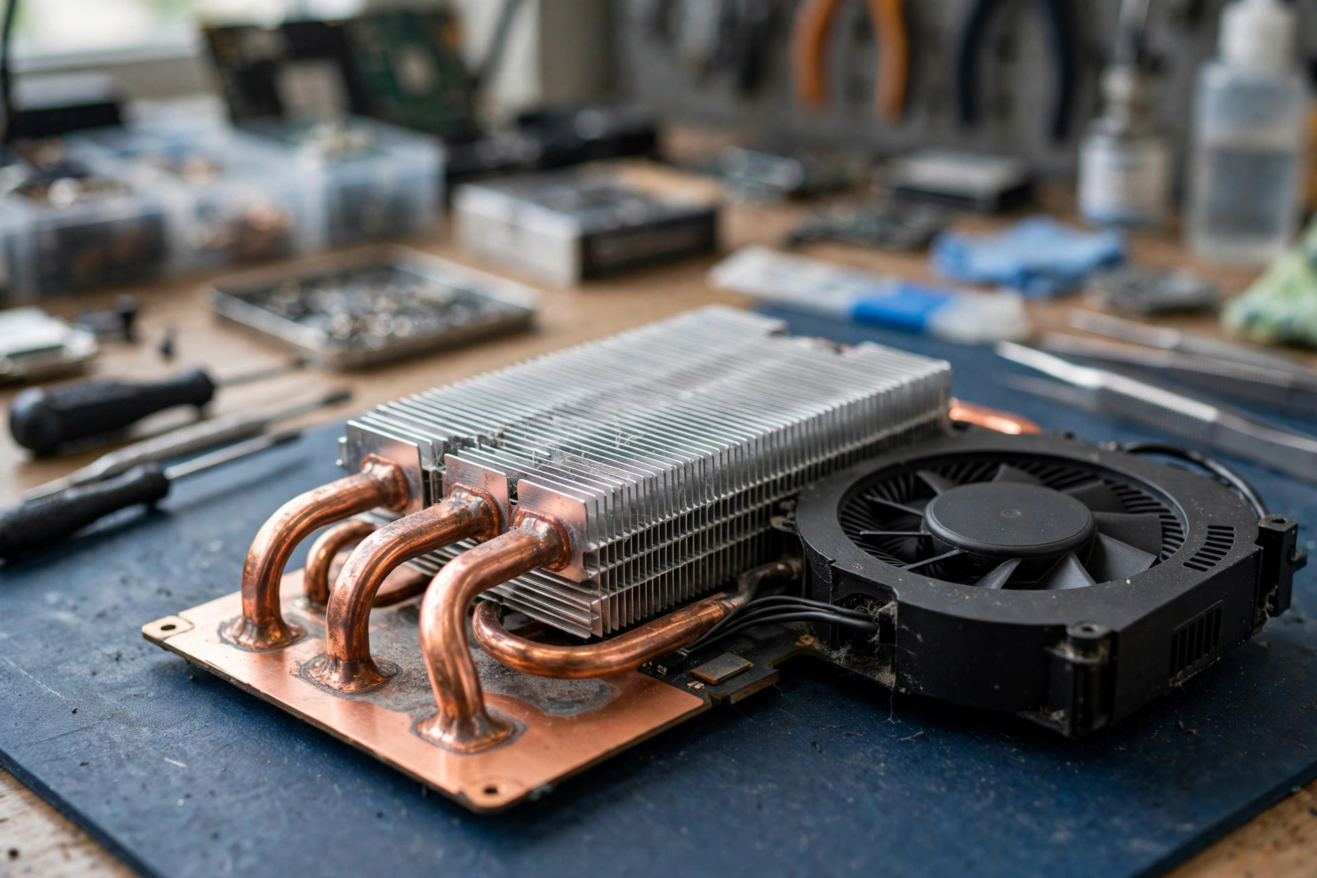
Scope: this guide covers only the thermal module, heat pipes, vapor chamber, fins, air duct, and interface layer
This guide covers only the laptop thermal module itself and its heat transfer chain, including the thermal interface layer, the copper base, heat pipes, the vapor chamber, the fin stack, the air duct and airflow path, and the way each link in that chain fails, with its externally observable symptoms, temperature distribution features, time curves, and layered exclusion logic. The following layers are mentioned only as contrasts and are not developed in this guide: the fan motor and bearing mechanical layer, which belongs to batch 92; the pulse width modulation control and speed feedback layer, which belongs to batch 91; the temperature sensor itself, which belongs to batch 90; and the motherboard power layer, which appears only by layer name in the layered comparison table and whose power mechanism and circuit judgment are not developed here. Readers of this guide only perform user-level safe observation and pre-inspection external checks, including listening to sound, noting the general region of surface warmth, recording when symptoms appear and under what load, recording whether symptoms change when placement changes, and noting airflow strength and exhaust warmth in general terms, and then handing those records to professional inspection for reference. All internal inspection is left to professional inspection. Readers must never disassemble the machine and must never open the chassis to handle internal parts. Any inspection, judgment, or handling that involves the inside of the machine is left to professional inspection, and readers must not diagnose which link has failed from any single sentence in this guide. The number of heat pipes, pipe diameter, wick type, fluid charge, fan curve, throttling threshold, and thermal module part number for a particular laptop model are, unless supported by that model's factory service manual or part specification, marked as unverified or model-dependent throughout this guide. Mechanism descriptions drawn from factory general technical documents or general engineering literature appear only after their source character and applicable conditions are noted, and numbers from desktop cooling or general heat pipes are never applied directly to a particular laptop.
The single question that drives this guide is where heat gets stuck. Laptop cooling is a series chain. Heat from a chip must pass through the thermal interface into a copper base or a vapor chamber evaporation zone, then be carried by two-phase transfer inside a heat pipe or vapor chamber to a fin stack, then be handed by fin surfaces to air flowing across the fins, and finally be exhausted through an outlet into room air. Heat pipes and vapor chambers do not manufacture cold air. They only move heat from one place to another. What actually removes heat from the machine is fin surface area together with air flowing across it. This distinction decides the whole diagnostic direction. Hot fins do not necessarily mean a healthy heat pipe, and cool fins do not necessarily mean a failed fan. Heat may never have reached the fins, or air may never have flowed across the fins. Advanced diagnosis does not rest on one temperature number. It rests on whether four groups of signals agree with each other: temperature, reported speed, perceived airflow, and temperature distribution.
Series thermal resistance is the second premise. Interface resistance, heat pipe equivalent resistance, and fin convection resistance add together. When any one of them worsens, chip temperature rises, but the rise curve, the fan response, the exhaust temperature, and the location of surface warmth differ. When the interface worsens, the temperature difference between chip and base widens, while the temperature distribution beyond the middle of the heat pipe may remain comparatively continuous. When the heat pipe itself fails, the difference between evaporation end and condensation end widens steeply, and the fins stay relatively cool. When fins are blocked or the duct leaks, heat reaches the fins but cannot be removed, so fins and exhaust stay warm while perceived airflow weakens. These three patterns can already be separated in broad terms at the external observation level, but they are only directions of suspicion, not diagnoses. Confirmation requires professional inspection under controlled load, with multi-point temperature comparison and sustained load retesting, and the test conditions must be recorded, including load type, duration, posture, and ambient temperature range. Without recorded conditions, a claim that a machine has been repaired cannot be verified by a third party. For pricing, see the pricing page, and for inspection arrangements, see the diagnostic page.
Chapter One: the thermal module is not one part but a chain
A laptop thermal module is normally a set of interlocking parts: a copper base or vapor chamber evaporation zone that contacts the chip, heat pipes or a vapor chamber cavity that extend from the base to the fin stack, a fin stack welded or pressed onto the condensation end of the pipes, a fan that pushes air across the fins, a duct cover and sealing foam that define the airflow path, a retention mechanism and screw set that fixes base pressure and position, a thermal interface that fills microscopic gaps between chip and base, and thermal pads that fill larger gaps between auxiliary components of uneven height and the module. A change in the geometric tolerance, contact pressure, weld state, or aging state of any one of these parts changes the resistance of the whole chain, yet symptoms often collapse into the same result: heat, slowness, noise, throttling, or sudden shutdown. Equating a symptom directly with one failed part is the shortcut this guide repeatedly corrects.
Compensation in a series chain has a ceiling. Raising fan speed can partly compensate for rising resistance and hold temperature below a throttling threshold, at the cost of noise, power draw, and fan load. Throttling itself can bring temperature down, at the cost of performance. A temperature number seen by a user is therefore often already a compensated result, not a direct measure of original resistance. Symptom records must therefore include load state, fan sound change, and the moment when performance drops, rather than a single temperature reading. Software temperature readings also carry error and sensor placement limits. When a sensor is not located on the hot spot, a reading can understate the true peak. The sensor itself belongs to batch 90, so this guide notes the effect only as a contrast and does not develop sensor structure.
| Chain link | How heat enters | Main function | Tendency when it fails |
|---|---|---|---|
| Thermal interface layer | Fills microscopic gaps and excludes air | Lets chip heat enter the base smoothly | Chip hot, base difference widened, short improvement after interface replacement |
| Copper base or vapor chamber evaporation zone | Solid conduction plus two-phase spreading | Spreads a small-area heat source | Local hot spot, one zone unusually hot when contact fails |
| Heat pipe or vapor chamber interior | Evaporation, vapor transport, condensation, capillary return | Moves heat from evaporation end to condensation end | Evaporation end extremely hot, condensation end cool, steep gradient |
| Fins and weld interface | Welded or pressed transfer plus convection | Spreads heat over a large surface for air | Uneven fin temperature, fins cool when detached from pipe |
| Air duct and outlet | Defined airflow path | Forces cool air across fins and exhausts hot air | Fan loud but exhaust weak, exhaust not hot while chip is hot |
| Fan layer as contrast | Pushes air | Provides airflow | Contrast only, mechanical layer belongs to batch 92 |
| Sensing and control layer as contrast | Commands and feedback | Decides fan speed and throttling timing | Contrast only, control belongs to batch 91 and sensor belongs to batch 90 |
| Motherboard power layer as contrast | Supply and limit signals | Decides usable power ceiling for the chip | Contrast only, power mechanism not developed here |
Chapter Two: how a heat pipe works, sealed envelope, wick, and a small charge of working fluid
A typical electronic heat pipe consists of three indispensable parts. The first is a sealed envelope. Laptop pipes are usually copper tubes, flattened to fit a thin chassis and sealed at both ends by welding. The envelope must remain gas-tight over the long term, because any micro-leak changes internal fluid quantity and vacuum level. The second is a wick, a porous structure lining the inner wall that draws condensed liquid back to the evaporation end. Wick type decides capillary force, permeability, and posture sensitivity, as discussed in Chapter Three. The third is a small charge of working fluid. Laptop heat pipes commonly use deionized water, subject to compatibility with a copper envelope. The tube is evacuated before a small quantity of liquid is charged, so that the fluid can boil and evaporate at a lower temperature. The word small matters. Fluid does not fill the whole tube. It just wets the wick and leaves a vapor passage. Too much fluid floods the condensation zone, and too little fluid leaves the evaporation end prone to dryout. Charge quantity is itself a design parameter, model-dependent, with no verified universal value.
The phase-change cycle has four steps and is passive, with no pump and no moving parts. The first step is evaporation. Chip heat enters the tube wall through the base, and liquid working fluid inside the wick absorbs heat and vaporizes, absorbing latent heat. Latent heat is the key. For the same mass of fluid, phase change carries far more heat than simple temperature rise, and that is the physical root of a heat pipe's equivalent conductivity being far higher than that of a solid copper rod. By how many times it is higher depends on pipe diameter, length, working fluid, and temperature, and this guide gives no universal multiplier, because no single multiplier applies everywhere. The second step is vapor transport. Vapor flows along the tube center from the high-pressure hot end toward the low-pressure cold end. In theory this section does not exchange heat with the outside, although in practice a small heat leak remains. The third step is condensation. Vapor meets the cooler tube wall in the fin zone, condenses, releases latent heat to the wall, and the wall hands that heat through fins to air. The fourth step is liquid return. Condensed liquid is drawn back to the evaporation end by capillary force in the wick, completing the loop. If any of the four steps breaks, the whole pipe degrades into a hollow copper tube. The solid copper envelope still conducts heat, but its cross-section is small and its path is long, so transfer capability falls sharply, appearing as an extremely hot evaporation end with a relatively cool condensation end and fin stack. That pattern is one of the most discriminating signals available to professional inspection.
Evacuation of the tube does not create suction. Its purpose is to lower the boiling point of the working fluid, so that the fluid can sustain an evaporation and condensation cycle within the chip's working temperature range, and evacuation also removes air from the tube, preventing air from occupying the condensation zone. Conversely, any process that lets air or non-condensable gas into the tube directly erodes effective condensation area. Non-condensable gas is treated separately in Chapter Six, because it is the quietest failure mode and the hardest to notice from outside. The first intuition readers should build is that heat pipe failure does not mean the copper has broken. It means the two-phase loop has broken. The copper envelope remains, but the phase-change cycle is no longer complete. That intuition explains why heat pipe failure symptoms are often sudden rather than linear.
| Phase-change step | Location | Energy form | Tendency when interrupted |
|---|---|---|---|
| Evaporation and heat absorption | Liquid inside the wick at the evaporation end | Liquid absorbs latent heat and becomes vapor | Evaporation end temperature jumps, local dry patches spread |
| Vapor transport | Tube center transport section | Vapor flows from high pressure to low pressure | Abnormal mid-pipe distribution, gradient changes when transport is obstructed |
| Condensation and heat release | Tube wall in the fin zone | Vapor releases latent heat and becomes liquid | Fins stay cool, heat cannot be handed to fins |
| Capillary return | Wick lining the inner wall | Capillary force draws liquid back to the evaporation end | Repeated dryout at the evaporation end when return is insufficient |
| Vacuum maintenance | Whole sealed tube | Lower boiling point, air excluded | After micro-leak, boiling conditions change and gas occupies condensation zone |
| Solid copper envelope as contrast | Tube wall itself | Solid conduction | After loop failure, only inefficient solid conduction remains and temperature difference widens |
Chapter Three: three wick families, sintered, grooved, and mesh trade-offs
A wick must satisfy three contradictory requirements at once. Capillary radius must be small, because finer pores give stronger capillary suction and can pull liquid back against gravity. Permeability must be high, because more open passages give lower liquid return resistance and higher flow. Thermal conduction must be good, because the wick layer itself must not become an insulating layer, or transfer from tube wall to liquid at the evaporation end will be obstructed. The three families are three different compromise points, and no family wins on all counts. Selection is decided jointly by heat flux density, transport distance, posture requirements, and thickness limits, and it is model-dependent.
A sintered powder wick is a porous layer formed by sintering copper powder at high temperature. Its pores are fine and numerous, its capillary force is high, and its permeability is relatively low, because fine pores mean high resistance. Its gravity and posture sensitivity are relatively low, it can work against gravity, and it suits arbitrary postures. It is the most common orientation for thin machines that change posture often, but a sintered layer is vulnerable to crush damage and to repeated freeze and thaw damage. A mesh wick is several layers of copper mesh rolled against the inner wall. Its capillary force is moderate, its permeability is moderate, and its gravity sensitivity is moderate, relying more on gravity assistance or horizontal use. Its cost is lower. When a laptop is used mainly horizontally it can still work, but its against-gravity margin is smaller. A grooved wick is axial grooves cut into the inner wall, with liquid returning along the grooves. Its capillary force is lower, because groove width means a larger capillary radius, its permeability is high, because groove passages are open, and its gravity sensitivity is high, making it most sensitive to posture, performing better horizontally or with gravity assistance. Laptops rarely use grooves alone. Grooves are commonly combined with mesh or sintering to balance suction and flow. A composite wick is the practical compromise in real designs, for example mesh over grooves, where grooves provide low-resistance passages and mesh provides a finer capillary radius. It would be wrong to write that sintered is always best. The correct statement is that, for the same diameter and length, sintered usually gives the strongest capillary force and the widest posture tolerance, but permeability and manufacturing cost are the price.
| Wick structure | Description | Capillary force | Permeability and flow | Posture sensitivity | Meaning for laptops |
|---|---|---|---|---|---|
| Sintered powder | Copper powder sintered into a porous layer | High | Relatively low | Relatively low | Common orientation for thin machines that change posture often, but vulnerable to crush damage |
| Mesh metal screen | Several layers of copper mesh lining the wall | Moderate | Moderate | Moderate | Works for mainly horizontal use, smaller against-gravity margin |
| Grooved | Axial grooves in the inner wall | Lower | High | High | Rarely used alone in laptops, common in composite wicks |
| Composite wick | Grooves covered by mesh or sintering | Balanced | Balanced | Between the two parents | Compromise design, actual behavior model-dependent |
| Vapor chamber wick layer | Porous layer inside a planar cavity | Depends on design | Depends on cavity thickness | Depends on design | Extremely thin cavity more sensitive to collapse and contamination |
Wick degradation is usually not a single overnight event but the sum of several degradations. Sintered layer micro-cracking or detachment can follow repeated thermal expansion and contraction, vibration, and freeze and thaw cycles. A factory question-and-answer document on vapor chambers notes that repeated freeze and thaw can damage wick structure and reduce performance, and that designs must leave margin for expected freeze and thaw cycles. In Hong Kong indoor use, freeze and thaw are not a daily scenario, but the edge case of long storage in a cold environment followed by reuse deserves a cautious mention, and it must not be exaggerated into a common Hong Kong failure. Corrosion products, working fluid impurities, and reaction products from non-condensable gas can deposit inside wick pores, shrinking effective pore size and reducing permeability, so capillary force and flow suffer together. A high-temperature water heat pipe life study notes that incompatibility leads precisely to corrosion products blocking part of the wick and preventing normal operation. Crush damage permanently reduces porosity and cannot be recovered by dust removal or interface replacement. That distinction matters for decisions. A crushed wick layer belongs to module failure, and its handling direction is whole module replacement rather than repeated interface work.
Chapter Four: five performance limits, a heat pipe does not move unlimited heat
A heat pipe transfer ceiling is not a fixed nameplate power rating. It is, under given working temperature, posture, length, bending, and flattening conditions, whichever of five limits is reached first. The same pipe has a different ceiling in a different posture or ambient temperature, so discussing a ceiling without its conditions is meaningless. Understanding this set of limits explains why the same pipe can fail suddenly under some loads instead of degrading linearly.
The capillary limit is the most common limit in practice. Capillary pressure difference must offset the sum of liquid return pressure drop, vapor flow pressure drop, and gravity head. Once evaporation rate exceeds capillary return capability, liquid supply at the evaporation end falls short, local dryout occurs, and thermal resistance jumps. The boiling limit occurs when local heat flux density at the evaporation end is too high. Bubbles nucleate inside the wick, push liquid away, and block return, so the wick dries locally. Unlike the capillary limit, the boiling limit is about heat being too concentrated. Even when total power is within limits, a local hot spot can trigger it. The entrainment limit occurs when high-speed vapor shears the liquid-vapor interface and carries returning liquid away. Liquid accumulates in the transport section, the condenser floods, and the evaporation end dries instead. The sonic limit occurs when vapor velocity at the evaporation end reaches the speed of sound, so further pressure reduction cannot raise flow further. It is commonly associated with cold start or low vapor density conditions. The viscous limit occurs at low temperature near the melting point of the working fluid, when liquid viscosity is highest and flow is dominated by viscosity. For laptops, the link between cold start and low-temperature conditions needs cautious wording. Laptop working temperatures are usually far above this zone, so the viscous limit is more a design boundary concept than a daily failure cause, and it is unverified as a common laptop failure and must not be exaggerated.
| Performance limit | Trigger condition | Internal process | External symptom tendency |
|---|---|---|---|
| Capillary limit | Evaporation rate exceeds capillary return capability | Evaporation end starved of liquid, local dryout | Appears only at high load, normal at light load, may recover when load drops |
| Boiling limit | Local heat flux density too high | Bubbles inside the wick block liquid return | Local hot spot worsens first, total power may still be within limits |
| Entrainment limit | Vapor velocity too high | Returning liquid carried away, condenser flooded | Evaporation end dry while condenser section accumulates liquid, behavior is inconsistent |
| Sonic limit | Cold start or low vapor density | Vapor velocity reaches its ceiling, flow limited | Insufficient transfer during start, may improve at steady state |
| Viscous limit | Temperature near working fluid melting point | Viscosity dominates flow | Design boundary concept, low weight as a daily laptop failure, unverified as common |
| Design ceiling as contrast | Model cooling margin itself insufficient | Sustained load exceeds original design ceiling | Replacing with the same module only restores original design level, never exceeds it |
Chapter Five: gravity and posture, why placement affects cooling but is not a universal explanation
Three postures are defined by the relative height of evaporation end and condensation end. In gravity-aided posture, the evaporation end is lower than the condensation end, liquid return is assisted by gravity, capillary burden is smallest, and performance is most favorable. In horizontal posture, the two ends are roughly level, there is no net gravity head, and capillary force alone bears return pressure drop. In against-gravity posture, the evaporation end is higher than the condensation end, liquid must flow upward back to the evaporation end, and capillary pressure difference must offset flow pressure drop plus an additional gravity head. Usable capillary margin is consumed, the ceiling falls, and in severe cases the evaporation end dries. Gravity assists a wickless thermosiphon, but it resists a wicked heat pipe in against-gravity posture. The longer the pipe, the harder it is for capillary force to overcome gravity, and the stronger the posture effect.
Applied to laptops, posture must be discussed at three levels, without exaggeration. The first level is that normal posture differences are limited. A laptop is usually placed horizontally on a desk, internal heat pipe routing is mostly roughly horizontal, and the height difference between evaporation end and condensation end is only on the order of chassis thickness, at centimeter scale. Gravity head itself is therefore small, and sintered wick against-gravity capability also has margin. A small change such as raising one corner slightly should not be written as the main cause of heat pipe failure. If a machine already overheats when flat, posture is not the first suspect. The second level is scenarios that genuinely amplify posture effects: vertical stands, tent mode, long-term use in a near-vertical posture, or models whose internal heat pipe routing already has a larger height difference. Those cases are model-dependent, with no verified list of specific models. In those scenarios, part of the capillary margin for the same load is consumed by gravity, a pipe that was just sufficient reaches its capillary limit earlier, and symptoms appear as intermittent throttling only at high load while light load looks completely normal. That is precisely why posture-related failure is hard to notice. The third level is that starting posture and steady-state posture must be separated. Research summaries note that if a product must cold start with the evaporation end above the condensation end, evaluation must be done by cold starting in that posture, not by warming up in a favorable posture and then changing posture for testing, because liquid distribution after warming differs from cold start distribution. For repair purposes, the lesson is that inspection should use sustained load testing in the user's actual posture, not only a short horizontal bench test.
| Posture type | Evaporation end versus condensation end | Capillary burden | Laptop note |
|---|---|---|---|
| Gravity-aided | Evaporation end lower than condensation end | Smallest | Most favorable, but height difference in horizontal laptop use is limited |
| Horizontal | Two ends roughly level | Capillary force alone | Most common laptop posture, differences limited |
| Against gravity | Evaporation end higher than condensation end | Extra gravity head must be offset | Noticeable in vertical or tent use, model-dependent |
| Cold start posture | Posture at the moment of starting | Liquid distribution not yet stable | Must be evaluated by cold starting in actual posture, warming first then changing posture is not a substitute |
| Base blockage as contrast | Air inlet blocked by a soft surface | Duct problem, not a gravity problem | Improvement on a hard surface points to duct first, not to heat pipe |
Flattening, bending, and deformation are inherent weak points of laptop heat pipes. Excessive flattening shrinks vapor passage cross-section, raises vapor flow resistance, compresses the wick layer, and shrinks liquid passages as well. Double resistance rises together and the ceiling falls. A sharp bend or kink compresses the wick on the inside of the bend and stretches it on the outside, and in severe cases locally closes the vapor passage. Repair forum discussions also observe that a pipe that is compressed but not fully closed may still transfer heat, while further bending may break it. That observation belongs to secondary experience with low weight, but its physical direction is correct: a compressed pipe should not be straightened again, because a second deformation may damage the seal or the wick. That sentence states a professional inspection judgment principle only. Readers must never disassemble the machine to handle a compressed heat pipe. For vapor chamber deformation, an ultra-thin chamber has an extremely small internal gap, and point pressure from fixtures, uneven screw torque, chassis tolerance squeezing, and uneven heating and cooling can all change flatness or cause local collapse. Factory technical articles note that deformation can reduce contact area, block vapor flow, and compress wick structure, that surface appearance may look slight while thermal performance is already damaged, and that passing a visual check does not mean internal function is normal. That point matters especially for replacement or repaired modules: fitting in place does not mean pressing correctly.
Chapter Six: why pipes fail, eight failure mechanisms from inside to outside
Dryout is not a single part breaking. It is the state in which liquid supply at the evaporation end cannot keep up with evaporation rate. It has at least four trigger paths: the capillary limit is exceeded, because load, posture, or flattening leaves return insufficient; the boiling limit, where local heat flux is too high and bubbles block return; the entrainment limit, where high-speed vapor carries returning liquid away; and insufficient total working fluid, where even a healthy wick has no liquid to supply. The physical process of dryout is gradual and then abrupt. Local dry patches first appear at the edge of the evaporation end, local resistance rises, dry patches expand, evaporation end temperature jumps sharply, and because rising wall temperature further accelerates evaporation, dry patches have a self-expanding positive feedback until the whole evaporation zone loses phase-change transfer and only solid copper conduction remains. In symptom terms, temperature jumps suddenly and throttling appears suddenly, rather than climbing slowly. That is an important difference from fin blockage, which climbs gradually. Reversible versus irreversible must be separated. Brief and slight dryout can recover when load drops and liquid returns to rewet the evaporation end. Repeated dryout combined with long-term high temperature, however, accelerates wick aging, working fluid and wall reaction, and interface aging, turning reversible into irreversible. It would be wrong to write that one dryout event means scrap, and equally wrong to write that recovery after load reduction means repair.
Working fluid loss is the most direct and irreversible failure of a sealed system. As liquid quantity falls, the evaporation end dries more easily, the ceiling falls, dryout becomes easier, and a vicious cycle forms. Loss paths include weld or seal defects, where the sealing weld formed during manufacture is an inherent weak point, long-term thermal cycling fatigues the weld, and micro-leakage can start extremely slowly with symptoms so slight at first that they are hard to notice; corrosion perforation, where external corrosion and internal corrosion can both eventually perforate the wall, and internal corrosion also generates non-condensable gas, so the two often coexist; and mechanical damage, where squeezing, dropping, backpack compression, or improper handling creates tube cracks or fin tearing that pulls at weld points. Repair forum discussions describing heat pipe weld leakage mostly belong to this kind of experience description, with low weight, but the mechanism itself fits sealed system physics, so this guide describes it as a possible path and never as a common fault of a particular model, which is unverified. The key diagnostic feature is that a leaking pipe shows an abnormally large evaporation-to-condensation temperature difference even with the fan at full speed and fins clean, and it worsens over time, with no improvement from interface replacement or dust removal.
| Failure mechanism | Root process | Time curve | Key discriminating signal |
|---|---|---|---|
| Dryout | Evaporation end supply cannot keep up with evaporation rate | Gradual then abrupt, sudden jump | May recover at light load, sudden throttling at heavy load |
| Working fluid loss | Weld, corrosion perforation, or mechanical damage breaks the seal | Worsens over time, irreversible | Large gradient, no improvement after dust removal or interface replacement |
| Wick aging and damage | Micro-cracking, detachment, blockage, crush damage | Slow worsening, or abrupt after compression | Appearance may be normal, interface replacement ineffective |
| Non-condensable gas accumulation | Reaction between fluid and wall, or air drawn in through micro-leak | Slow and gradual, over months or years | Condensation end tail abnormally cold, cold end phenomenon |
| Oxidation and corrosion | External oxidation, internal corrosion, dissimilar metal galvanic corrosion | Long-term accumulation | Fin to pipe joints loosening, wall thinning |
| Interface aging | Pump-out, dry cracking, phase-change material failure, pad hardening | Gradual, short improvement possible after interface replacement | Chip to base difference widened, center exposed |
| Fin collapse and blockage | Dust felt, collapse, detachment from pipe | Gradual, over months to years | Fan loud but exhaust weak, uneven fin temperature |
| Duct bypass and short circuit | Duct cover damage, seal aging, outlet blockage | Depends on damage, can be abrupt or gradual | Fan at full speed but fin zone airflow insufficient |
Non-condensable gas accumulation is the quietest killer and must be treated separately. Vapor pushes non-condensable gas toward the far end of the condensation zone, where gas accumulates into a gas plug. The condensation zone occupied by the plug can no longer receive vapor for condensation, effective condensation area shrinks, resistance rises, and end-to-end temperature difference widens. In severe cases the condensation end tail shows a cold end, meaning tail temperature is clearly lower than mid-pipe temperature. That pattern is a classic signal used in life testing to monitor incompatibility. Sources of gas include incompatibility reaction between working fluid and tube wall. The classic example is reaction between water and iron-based material generating hydrogen gas. The more hydrogen, the worse the transfer, and accumulation beyond a certain point can make a heat pipe lose transfer function entirely. That mechanism is described with an explicit chemical formula in steel and water heat pipe literature. Copper and water compatibility is better, but not zero reaction. Long-term high temperature, impurities, water quality, and manufacturing residue can all affect actual gas generation rate. The gas generation rate for a particular laptop model is unverified and must not be quantified. Two further sources are manufacturing residual gas, including incomplete evacuation and material outgassing, and air drawn in through micro-leakage after seal degradation. Although the quantity is small, non-condensable gas does not participate in circulation and only accumulates, so its long-term effect is amplified. The diagnostic difficulty is that appearance is completely normal, fan is normal, fins are clean, interface is newly replaced, and temperature remains high. Only temperature distribution along the pipe can hint at it, with a hot evaporation end, a cooler middle, and an abnormally cold tail. Replacing the whole module is the only thorough handling direction, as set out in the decision framework in Chapter Thirteen.
Oxidation and corrosion proceed on two fronts, inside and outside. On the external front, copper forms an oxide layer in humid air, and chloride ions in salt spray can penetrate the oxide layer and form hygroscopic chlorides, creating a self-sustaining cycle of moisture absorption, corrosion, and further moisture absorption. A Hong Kong atmospheric corrosion study notes that high-salt warm sea air in summer corrodes metal structures and that commercial buildings around Victoria Harbour are affected by atmospheric corrosion throughout the year. That study examined building steel structures and cannot be applied directly to the corrosion rate of laptop copper pipes, but the mechanism direction, that salt spray plus humidity accelerates metal corrosion, is shared. This guide marks that inference boundary explicitly. On the internal front, corrosion products from incompatibility reactions block wicks and can also thin the wall, eventually perforating it and leaking working fluid. On the fin front, aluminum fins and copper pipes form a dissimilar metal contact surface that can suffer galvanic corrosion under a moist electrolyte such as condensation or salt spray deposits. Corrosion loosening at fin to pipe weld or press joints is equivalent to fins detaching from the pipe. Heat reaches the pipe but cannot be handed to fins.
Long-term high temperature accelerates aging, and almost all degradations above, including interface oil volatilization, working fluid and wall reaction, weld fatigue, and corrosion, accelerate as temperature rises. That is the general direction of chemical kinetics. Acceleration multiples differ by material and reaction, however, and this guide does not apply a universal rule such as halving life for every fixed temperature rise to heat pipes or thermal paste. That experience rule comes from other fields and is unverified for this subject. The correct statement is qualitative: long-term high load plus high ambient temperature plus poor ventilation together accelerate all degradations in parallel, forming a vicious cycle in which hotter machines fail more easily and failed machines run hotter. Breaking the cycle requires restoring duct and interface first, rather than only reducing frequency or only replacing a fan. For pricing, see the pricing page, and for inspection arrangements, see the diagnostic page.
Chapter Seven: thermal interface aging, pump-out, dry cracking, phase-change failure, and pad hardening
The interface is not the heat pipe itself, but it is the first link in the chain, and its aging is often mistaken for heat pipe failure. The first degradation is pump-out. Chip and heatsink base have different thermal expansion coefficients, and repeated heating and cooling pumps the interface layer toward the edges, thinning or even exposing the central hot spot zone while material accumulates as a ring at the edges. Low-viscosity, thicker bond line, non-curing paste is more vulnerable. Laptops tend to show pump-out more clearly because bases are light, retention pressure is lower than in desktop machines, and direct die contact fears cracking, so the tendency is stronger. That statement follows secondary technical summaries and must be marked as model-dependent and interface-material-dependent. The second degradation is dry cracking or oil separation. Carrier oil volatilizes or migrates into porous surfaces, filler remains as a powdery, cracked layer, and wetting and gap-filling ability are lost. The edge of the layer may still look moist while the central hot spot is already starved of paste. That is a common misjudgment: a moist edge seen during professional inspection does not mean the interface is still effective. That sentence describes a professional inspection observation only. Readers must never disassemble the machine to check an interface. The third degradation is phase-change material failure. A phase-change pad is solid at room temperature, softens when heated to fill microscopic gaps, and resolidifies on cooling. Factory or secondary summaries claim better pump-out and dryout resistance than traditional paste, but phase-change material still fails: filler migration after repeated phase changes, insufficient installation pressure preventing full softening and filling, wrong thickness selection making the bond line too thick, and compatibility problems with a particular base material. Its actual life and failure rate depend on product and installation and have no verified universal number. It must not be written that a phase-change pad never ages, and no single brand or model must be written as the only solution. The fourth degradation is thermal pad aging. Pads used for memory chips and power components harden, take a permanent compression set, and bleed oil, so contact pressure and gap-filling ability fall together. Because those components often have no independent temperature sensor, aging often appears as whole-machine instability or intermittent throttling rather than a single temperature number.
Thermal paste consists of conductive filler suspended in silicone oil or synthetic oil carrier, in a non-curing form that stays soft and flowable. Beyond pump-out and dry cracking, filler settling and uneven distribution can occur. After long storage and thermal cycling, filler distribution may become uneven, with filler-rich and filler-poor zones and uneven resistance distribution. That statement is a mechanism inference and is unverified at specific product level. For phase-change pads, factory data summaries mention a particular pad's phase-change temperature, conductivity, and thermal impedance nameplate values, together with factory durability test summaries. Those numbers must be noted as factory data summaries, not independently verified factory original documents, and must not be treated as independent verification results. Phase-change weaknesses also include the need for complete burn-in or thermal setting. Measurements show that a phase-change pad needs the whole pad temperature to reach a certain level before setting completes. If heatsink side temperature is insufficient, the pad may not fully convert, and performance may not reach its nameplate level. It must not be written that performance is best immediately after application. A sufficient thermal load setting process must be described. Thickness and pressure sensitivity are also key. Final bond line thickness depends on assembly pressure and original thickness, and insufficient pressure, an uneven base, or loose retention all reduce effectiveness. Measurements also note pads of different thickness and composition sold under the same name with different performance. This guide therefore advises judging by model and factory specification, but it must not accuse any particular seller or channel of selling counterfeit goods, which is unverified.
| Interface material | Form and use | Main aging pattern | How to read the result after interface replacement |
|---|---|---|---|
| Thermal paste | Non-curing paste filling main chip gaps | Pump-out, dry cracking, oil separation, filler settling | Clear and lasting improvement points to a single interface factor |
| Phase-change pad | Solid pad, softens when heated then resolidifies | Filler migration, incomplete setting, wrong thickness selection | Short improvement then relapse points to pump-out or assembly problems |
| Thermal pad | Preformed elastic body filling large gaps | Hardening, permanent compression set, oil bleeding, thickness mismatch | Improvement on one side only points to a shared module path problem |
| Liquid metal | Liquid alloy, factory production line process | Conductive migration and overflow, gallium and aluminum reaction, copper gallium alloy layer | Worse after replacement points to thickness, quantity, pressure, or migration problems |
A thermal pad is not a substitute for thermal paste. Main chip interfaces normally use paste or phase-change material, while memory and power components of uneven height use thermal pads. Confusing the two is a common source of misdiagnosis. Pad thickness must match the actual gap. Too thin, and contact is missed. Too thick, and the module cannot press the main chip correctly, so the main chip paste or phase-change interface fails instead. That is a common mechanism for getting hotter after pad replacement. After long compression plus high temperature, a pad loses elastic recovery. Once a module is removed and refitted during professional inspection, the original pad may not recover its original thickness and contact pressure, causing poor contact. That phenomenon belongs to professional inspection observation. Readers do not need and must not verify it themselves.
Interface replacement is an interface layer experiment, not a universal cure, and its result is itself diagnostic information. Clear improvement that lasts points to genuinely aged original interface material, with heat pipe, fan, and fins themselves normal, but observation must continue for rapid re-worsening, which may indicate another factor accelerating interface aging, such as insufficient assembly pressure or an uneven base. Short improvement followed by return to the original state within weeks to months points to rapid pump-out of the new material, because thermal cycling is severe, gap change is large, or material selection is unsuitable, or the root problem is assembly pressure or base flatness, with interface replacement only briefly masking it. No improvement at all points away from the interface: heat pipe failure, fin blockage, fan failure, weld interface failure, or sensing and control layer problems are all possible, and repeated interface replacement must stop in favor of layered inspection to locate which link holds resistance. Worse after replacement points to thickness, quantity, or pressure problems, or liquid metal migration and contamination, or poor contact after assembly, and high load use must stop immediately for professional inspection of interface state, without repeated trial and error by refitting. Improvement for the processor only, without improvement for the graphics processor, or the reverse, points to one pipe, one interface path, or one fin zone in a shared module failing while the other path stays normal, requiring path-by-path inspection by heat source.
Chapter Eight: fins, vapor chamber, and air duct, three battlegrounds beyond heat pipes
Fin function is to spread heat delivered by pipes or a vapor chamber over a large surface for air. Failure modes are fourfold. The first is blockage. Dust, fibers, and hair form a felt-like layer between fins, resistance rises sharply, and effective area falls. Factory support documents explicitly list lint and dust on fins preventing air from flowing across fins, with the fan working harder and louder, as one cause of overheating. Blockage is gradual, with fans intervening earlier and louder over months to years, even at light load. The second is collapse or bending. Fins are extremely thin, and squeezing, dropping, or handling contact can collapse local fins into each other. A few bent fins have limited effect on total area, following the consensus direction of secondary discussion, but large-area collapse shrinks duct cross-section, greatly raises local resistance, and forces airflow to bypass, which is equivalent to blockage. More importantly, collapsed fins can press against fan blades or chassis, causing abnormal noise and vibration. The third is detachment from welding or pressing. When fin to pipe weld or press joints loosen, heat cannot pass from pipe to fins, appearing as a hot pipe evaporation end with cool fins, overlapping the heat pipe failure pattern and requiring temperature distribution plus visual inspection at professional level to separate. The fourth is oxidation and corrosion. A fin surface oxide layer conducts poorly and is rough, and long-term convection efficiency can fall, but equating discoloration with a need for replacement is over-inference. Surface oxidation and functional failure must be verified by temperature and airflow, not judged by color.
| Fin failure mode | Formation process | Airflow and temperature features | Easy misjudgment |
|---|---|---|---|
| Felt blockage | Dust and fibers form a felt layer between fins | Fan loud but exhaust weak, gradual worsening | Clean appearance outside does not mean clear inside |
| Large-area collapse | Squeezing or dropping collapses fins together | Duct cross-section shrinks, airflow bypasses | A few bent fins matter little, large area matters greatly |
| Weld or press detachment | Weld or press joints loosen | Pipe hot, fins cool | Overlaps heat pipe body failure pattern |
| Oxidation and corrosion | Surface oxide layer thickens and roughens | Convection efficiency falls slowly | Discoloration does not equal functional failure, data verification needed |
An air duct means the defined airflow path among fan, fins, and outlet, commonly formed jointly by a plastic duct cover, foam sealing strips, and chassis inner walls. Bypass leakage and short circuit are the most underestimated failures. Bypass leakage means a damaged duct cover, aged and detached sealing foam, or deformed bottom cover lets intake cool air escape through gaps without passing fins, or lets hot air circulate inside the machine without leaving it. Its appearance is highly deceptive: fan at full speed, wind felt somewhere on the chassis, but fin zone airflow insufficient and exhaust temperature not high, because air never flowed across fins. Short circuit means an outlet blocked by placement on a soft surface, close to a wall, or a covered bottom inlet, or intake and exhaust connected inside the machine, so hot air is drawn back in by the fan, intake temperature is raised, and cooling temperature difference shrinks. Factory documents also list blocked fan or outlet as an overheating cause. Duct wall dust accumulation differs from fin blockage. A dust layer on duct walls changes passage cross-section and roughness, shifting fan operating point. In severe cases, actual airflow at the same reported speed has already fallen, while speed reporting remains normal. Normal reported speed does not equal normal airflow. That is the first rule of duct diagnosis.
| Duct failure mode | Cause | Observable feature | Separation from other layers |
|---|---|---|---|
| Bypass leakage | Duct cover damage, sealing foam detachment, bottom cover deformation | Fan loud, wind present, but fin zone airflow insufficient | Fan itself may be normal, problem is the path |
| Short circuit return flow | Outlet blockage, intake and exhaust connected inside | Intake temperature raised, temperature difference shrunk | Moving to a hard surface and removing blockage may improve it |
| Duct wall dust accumulation | Wall dust layer changes cross-section and roughness | Reported speed normal but actual airflow fallen | Normal speed does not equal normal airflow |
| Dual fan single side failure as contrast | One side stopped or insufficient, other side compensates | One side throttles first, left and right exhaust asymmetric | Contrast only, fan mechanical layer belongs to batch 92 |
Thin versus gaming design trade-offs belong to design level, not quality judgment. Thin machines have a lower power ceiling and are designed to throttle earlier, small thermal capacity, fast temperature change and fast thermal saturation, low noise tolerance, a conservative fan curve that prefers throttling to full speed, thin fins with fine gaps that show blockage effects more clearly, low pipe redundancy where single-point failure matters greatly, and modules tightly integrated with other components requiring matching model modules for replacement. Gaming machines and workstations have a higher power ceiling and aim to sustain high power for long periods, large thermal capacity, slower temperature climb but also slower recovery after saturation, fans that can run at high speed for long periods with noise as part of the trade-off, thick fins with large airflow that tolerate slight blockage better but fail equally under severe blockage, higher pipe redundancy but more complex fault location under shared design, and larger modules that still require matching models and cannot be substituted across models. The above is a qualitative design trade-off description. It must not be written that thin machines always fail easily or gaming machines always last longer. Failure rate depends on specific design, manufacturing, and use environment, with no reliable statistics available for citation, and uncertain wording must be preserved.
Chapter Nine: which layer has failed, seven-layer exclusion from outside to inside and from easy to hard
Exclusion order runs from outside to inside and from easy to hard. Its purpose is not to replace every part at once, but to exclude one layer at a time and record whether symptoms change after each layer is handled. The seven layers are defined as follows. The environment and use layer covers room temperature, placement surface, outlet blockage, power mode, and performance mode. Its typical observable signal is a clear symptom change after changing environment or placement, worsening on a soft surface and improving on a hard surface. The fan layer covers speed, abnormal noise, vibration, stopping, and zero-speed mode misjudgment. Its typical signals are inconsistency between reported speed and actual airflow or sound, noise changing with speed, and no wind under load. Fan mechanical detail belongs to batch 92, so this guide uses the layer name only as a contrast. The duct and fin layer covers blockage, collapse, bypass leakage, and short circuit. Its typical signals are a loud fan with weak exhaust, exhaust not hot while the chip is hot, and local surface hot spots inconsistent with duct routing. The thermal interface layer covers paste, phase-change pad, and thermal pad aging, plus thickness and pressure problems. Its typical signal is clear improvement after interface replacement, subject to confusion from duct handling done at the same time, with professional inspection findings of center exposure, edge accumulation, or dry cracking belonging to interface layer description. The heat pipe and vapor chamber body layer covers working fluid loss, non-condensable gas, wick damage, flattening and bending, and weld micro-leakage. Its typical signal is an abnormal temperature gradient along the pipe, with an extremely hot evaporation end and cool condensation end and fins, persisting after dust removal, interface replacement, and fan replacement. The sensing and control layer covers temperature sensor drift or failure, embedded controller fan control, firmware fan curves, and performance mode settings. Its typical signals are temperature readings inconsistent with actual surface warmth, a fan that does not speed up at high temperature, and a fan curve clearly deviating from factory expectation, model-dependent. The sensor itself belongs to batch 90 and the control layer belongs to batch 91, so this guide uses them only as contrasts. The motherboard power and chip body layer covers power components, power limits, and chip body abnormalities. Its typical signals are throttling before a temperature threshold is reached, separation between power limit indication and temperature indication, and no symptom change after thermal module replacement. Motherboard power appears only as a contrast and its mechanism is not developed here.
| Layer | Contents | Typical observable signal | How this guide treats it |
|---|---|---|---|
| Environment and use | Room temperature, placement surface, outlet blockage, performance mode | Clear change after changing environment or placement | Developed in detail, belongs to user observation |
| Fan | Speed, noise, vibration, stopping | Reported speed inconsistent with airflow or sound | Contrast only, mechanical layer belongs to batch 92 |
| Duct and fins | Blockage, collapse, bypass leakage, short circuit | Loud fan with weak exhaust, exhaust not hot while chip is hot | Developed in detail |
| Thermal interface | Paste, phase-change pad, thermal pad aging and pressure | Improvement after interface replacement, subject to confusion | Developed in detail |
| Heat pipe and vapor chamber body | Fluid loss, gas, wick damage, flattening | Abnormal gradient along the pipe, no improvement after other layers handled | Developed in detail, core of this guide |
| Sensing and control | Sensor drift, control abnormality, fan curve, performance mode | Reading inconsistent with reality, no speed increase at high temperature | Contrast only, batch 90 and batch 91 scope |
| Motherboard power and chip body | Power supply, power limits, chip body abnormality | Throttling before threshold, limit and temperature indications separated | Contrast only, power mechanism not developed |
Need a laptop repair expert?
Free diagnosis · Transparent pricing · No fix, no fee · 180-day warranty
The symptom overlap table is the most important section in this chapter, because almost every misdiagnosis comes from convicting a layer from a single symptom. A fan at full speed for a long time, very loud, can point to duct blockage, interface aging, heat pipe failure, high environmental load, or fan curve abnormality. Judging only by sound mislabels it as fan failure. A loud fan proves precisely that the fan is still working, and the problem usually lies in the resistance the fan must fight. A hot chip with cool exhaust can point to heat pipe failure, interface failure, or abnormal chip body heating. Cool exhaust does not mean the fan is not working. Heat may never have reached the fins. A hot chip with very hot exhaust can point to insufficient airflow, high ambient temperature, or high load itself. Heat has reached fins and is being exhausted, so the problem is removal capacity lagging production, not necessarily a broken heat pipe. Normal at light load with sudden throttling at heavy load can point to a capillary limit, posture, a power limit, or sensing delay. Passing a light load test creates a false repaired impression, so retesting must use sustained load in actual posture. Throttling with a low temperature reading can point to a power limit, sensor drift, or battery buffering failure. Using temperature alone mislabels it as a software problem when cooling is supposedly sufficient, so power limit indication must be compared. Short improvement after interface replacement with relapse within weeks points to pump-out relapse, a heat pipe body problem temporarily masked, or retention pressure problems. Short improvement does not mean the root cause is gone. Relapse interval itself is diagnostic information. Overheating on only one side or one chip can point to shared pipe interaction between processor and graphics processor, local fin blockage, local interface failure, or vapor chamber local dryout. In a shared pipe design, processor heat can raise graphics temperature readings through the same pipe, and vice versa. Secondary design summaries note that a colder shared pipe section between processor and graphics processor can cause premature condensation and affect efficiency, as a design trade-off, model-dependent.
| Symptom | Layers it can point to | Misleading aspect |
|---|---|---|
| Fan at full speed for a long time, very loud | Duct blockage, interface aging, heat pipe failure, high environmental load, control abnormality | Judging by sound alone mislabels it as fan failure, while loudness proves the fan is fighting resistance |
| Hot chip but cool exhaust | Heat pipe failure, interface failure, chip body abnormal heating | Cool exhaust does not mean the fan is not working, heat may not have reached fins |
| Hot chip and very hot exhaust | Insufficient airflow, high ambient temperature, high load itself | Heat is being exhausted, problem is removal capacity lagging production |
| Normal at light load, sudden throttling at heavy load | Capillary limit, posture, power limit, sensing delay | Light load pass creates a false repaired impression, sustained load retesting required |
| Throttling but low temperature reading | Power limit, sensor drift, battery buffering failure | Temperature alone mislabels it as a software problem, limit indication must be compared |
| Short improvement after interface replacement, relapse within weeks | Pump-out relapse, body problem masked, retention pressure | Short improvement does not mean root cause removed, relapse interval is information |
| Only one side or one chip overheating | Shared pipe interaction, local blockage, local interface failure, vapor chamber local dryout | Testing one side only misjudges the other side, three load conditions required |
| Time curve prototype | Appearance | Suspected direction | Common point |
|---|---|---|---|
| Start hot | High temperature under light load, fast throttling | Seal failure, severe interface failure, contact failure, fan stopping | Transfer chain already broken at the start |
| Slow then throttle | Climb after sustained load, slow recovery | Capillary limit insufficiency, fin blockage saturation, interface aging | Accumulation outpaces removal |
| Fluctuating fan cycling | Repeated crossing near threshold | Control layer interacting with rising resistance | Oscillation among throttling, cooling, recovery, reheating |
| Specific posture or load combination only | Normal ordinarily, failure only in a specific combination | Shared module distribution, capillary direction sensitivity, duct blockage | Single condition testing cannot reproduce it |
Chapter Ten: discriminating signals at professional inspection level, what to observe and what to compare
The following judgment logic at phenomenon level is available to professional inspection. It describes only what to observe and what to compare, without internal operating instructions. Readers perform only user-level observation, and all internal inspection is left to professional inspection. The first signal is temperature gradient along the pipe. Under sustained load, a normal heat pipe should fall gently from evaporation end to condensation end. A failed heat pipe often shows a steep gradient, with an extremely hot evaporation end and clearly cool condensation end and fins. Severe non-condensable gas shows an abnormally cold condensation end tail, called a cold end. A single point temperature is meaningless. Gradient is meaningful. The second signal is fin temperature versus chip temperature. A hot chip with cool fins points to heat not reaching fins, prioritizing interface or heat pipe body layers. A hot chip with hot fins and hot exhaust points to heat reaching fins but not being removed, prioritizing duct or environment layers. The third signal is airflow versus speed. Normal reported speed with weak exhaust points to duct or fin problems before fan body. Abnormal or absent speed reporting points to fan or control layers first, with control belonging to batch 91. The fourth signal is load and temperature curve shape. Gradual climbing mostly indicates blockage or interface aging. Sudden jumping plus sudden throttling mostly indicates dryout, capillary limit, or power limit. Normal at light load with failure only at heavy load mostly indicates insufficient ceiling, posture, or power limit. The fifth signal is relapse interval. Relapse within weeks after interface replacement suggests pump-out, retention pressure, or heat pipe body problems, rather than interface material quality alone. The sixth signal is multi-sensor comparison. Processor, graphics, motherboard, and power zone sensors are compared with each other. When a single sensor is abnormal while others are normal, sensing and control layers are suspected first, rather than the whole thermal module. The sensor itself belongs to batch 90. The seventh signal is before-and-after comparison under the same load. Only comparison under the same work load, same ambient temperature, and same posture can judge whether a handling step worked. Comparisons that change environment, load, or posture are not comparable. For inspection ethics, any inspection conclusion should record test conditions, including load type, duration, posture, and ambient temperature range. Without those conditions, a repaired claim cannot be verified by a third party.
| Discriminating signal | Normal pattern | Abnormal pattern | Layer prioritized |
|---|---|---|---|
| Temperature gradient along the pipe | Gentle fall from evaporation end to condensation end | Extremely hot evaporation end, cool condensation end, cold tail | Heat pipe body layer |
| Fin temperature versus chip temperature | Both rise together | Hot chip with cool fins, or both hot with hot exhaust | Former points to transfer layer, latter to removal layer |
| Airflow versus speed | Airflow rises together with speed | Normal speed with weak airflow, or abnormal speed | Former points to duct layer, latter to fan or control layer |
| Load and temperature curve shape | Smooth change with load | Sudden jump, sudden throttling | Dryout, capillary limit, power limit |
| Relapse interval | Long-term stability after handling | Relapse within weeks | Pump-out, retention pressure, body problem |
| Multi-sensor comparison | Sensors agree with each other | Single sensor abnormal, others normal | Sensing and control layer |
| Same load before and after comparison | Improvement repeatable under same conditions | Improvement disappears after conditions change | Comparison conditions themselves are flawed |
Software level monitoring belongs to a non-invasive recording level. It can record processor and graphics temperature, clock speed, and power draw over time, whether a throttling flag appears and when, the relationship between fan speed and temperature when tools can read speed, and performance under three load conditions: processor-only, graphics-only, and combined load. Software level monitoring can confirm whether throttling is real, meaning clock speed falls together with a throttling flag, rather than a subjective feeling of slowness. It can confirm the relationship between throttling and temperature, whether throttling starts immediately at a threshold or already at low temperature. The latter points to external limit signals, skin temperature power management, power limits, and other non-pure-temperature factors, treated here only as contrasts and not developed. Software level monitoring cannot locate which link holds resistance, because interface, heat pipe, fin, and fan symptoms overlap heavily at software level. It cannot distinguish causes of normal temperature readings with throttling already present, including sensor point deviation, throttling masking, fan compensation masking, external limit signal amplification, and surface versus junction temperature separation. Sensing and control mechanism belongs to batch 90 and batch 91. Software readings themselves carry error and must not use a difference of one or two degrees as diagnostic proof.
Professional non-invasive inspection belongs to a low-invasiveness instrument level. For infrared temperature distribution, the principle is photographing surface, fin, and outlet temperature distribution with an infrared camera to locate hot spots and gradients. Its value is detecting local dryout, non-condensable gas accumulation, weld defects, and fin blocked zones. Its limits and traps must be stated: bright metal surfaces have low emissivity, so infrared readings understate true temperature and require high-emissivity patches, emissivity correction, or similar methods, or numbers are fabricated; infrared measures only surface temperature, not junction temperature directly and not heat pipe internal temperature directly; measurement must occur under meaningful load, because faults may hide without load; and comparison must use distribution under the same load and same environment, not absolute temperature alone. For heat pipe end-to-end temperature difference measurement, the principle is measuring evaporation end and condensation end temperature difference under controlled load. A normal heat pipe end-to-end difference should be relatively small, reflecting two-phase isothermal character, while a failed pipe difference widens abnormally. Its value is the key indicator separating heat not passing through the pipe from heat not leaving fins. If the evaporation end is extremely hot and the condensation end is cool, the transfer link is indicated. If both ends are hot and fins are also hot, the removal link is indicated. Its limits are the need for professional instruments and repeatable load conditions, with measurement point position, contact method, and ambient temperature all affecting results. This research found no verified factory public normal difference threshold, so this guide gives no specific degree standard, only a qualitative judgment of abnormal widening, with comparison against a normal module of the same model when available. For airflow and fan inspection, professional measurement of fan speed, airflow, and exhaust symmetry can separate fan body failure from fin blockage. Normal fan speed with weak airflow points to blockage, while abnormal speed, abnormal noise, or vibration points to fan body, with fan mechanical detail belonging to batch 92. Professional non-invasive inspection can locate which segment heat breaks in, including transfer versus removal, left versus right, and processor path versus graphics path, but it cannot directly see inside a heat pipe, including wick structure, non-condensable gas, and fluid quantity. Final confirmation still requires professional internal inspection judgment.
| Inspection level | Invasiveness | What it can confirm | What it cannot confirm | Next step |
|---|---|---|---|---|
| User observation | None | Symptom pattern, time curve, distribution features | Any single fault | Record four items, move to software comparison |
| Software monitoring | None | Whether throttling is real, throttling and temperature relationship, asymmetric performance | Resistance location, masking cause | Design comparison loads, move to professional non-invasive inspection |
| Professional non-invasive inspection | Low, instrument level | Which segment heat breaks in, left and right asymmetry | Heat pipe internal state | After locating, move to professional internal inspection judgment |
| Professional internal inspection judgment | High, by model manual and by professionals | Mechanical damage, blockage, interface state, contact state | Internal gas and wick damage, settled by replacement comparison | Verify by replacing with a matching model module |
Chapter Eleven: Hong Kong context, humidity, salt spray, vibration, dust clumping, and temperature difference condensation
Hong Kong has a subtropical coastal climate. Observatory climatological normals show annual mean relative humidity around 78 percent for the 1991 to 2020 normals, and summer high-salt warm sea air effects on metal structure corrosion are supported by a local university study, with the study object being building steel structures, as noted in the boundary explanation in Chapter Six. Applied to laptop thermal modules, the reasonable mechanism chain is that high humidity makes continuous water films form more easily on metal surfaces, becoming an electrolyte for electrochemical corrosion; sea salt aerosol deposits are hygroscopic, so even when a surface looks dry, salt particles can absorb moisture and maintain local wetness, extending time of wetness; and copper pipe outer walls, aluminum fins, and dissimilar metal joints corrode faster under those conditions, eventually loosening fin to pipe joints and thinning pipe walls. The boundary must be stated clearly. The above is mechanism inference. The actual corrosion rate of laptop copper pipes in Hong Kong indoor use is unverified, and building steel corrosion rate numbers must not be applied to laptops. Indoor air-conditioned environments and coastal outdoor exposure must not be equated either. Humidity plus salt spray is an accelerating factor, not a necessary cause. The same model can age at different speeds in different use environments, so diagnosis should ask about use environment, including near-sea location, kitchen oil smoke, and construction dust, rather than blaming climate in general. It must not be written that Hong Kong laptop heat pipe life is necessarily shorter, or any specific life number, because this research found no reliable statistics of that kind.
| Hong Kong factor | Mechanism direction | Possible effect on thermal modules | Evidence level and boundary |
|---|---|---|---|
| High humidity | Continuous water film on metal becomes an electrolyte | Faster outer wall oxidation and joint corrosion | Mechanism inference, laptop copper pipe rate unverified |
| Salt spray deposits | Chloride penetrates oxide layers, hygroscopic salt extends wet time | Pitting, dissimilar metal galvanic corrosion, joint loosening | Building steel research cannot directly supply a rate |
| Dust plus moisture clumping | Moisture binds dust particles and sticks them to fins | Denser felt clumps, larger airflow resistance rise | Mechanism inference, no verified quantitative data |
| Commuting vibration | Continuous micro-vibration on trains and buses, repeated lid opening and closing | Fin collapse, duct cover deformation, retention loosening, weld fatigue | Qualitative inference, no verified specific life data |
| Backpack compression | Pressure inside backpacks, corner impacts, heavy objects pressing | Fatigue at pipe bends, weld micro-cracks, contact pressure fall | Sudden worsening after squeezing or dropping points to mechanical factors first |
| Air-conditioned room temperature difference | Cold surface below dew point in humid air condenses moisture | Short surface condensation as an edge risk, internal effect unverified | Theoretical possibility, must not be written as a Hong Kong common fault |
Commuting vibration and backpack compression form a cumulative account of mechanical stress. Daily commuting exposes laptops to backpack pressure, corner impacts, train and bus vibration, and repeated lid opening and closing bending, especially for models whose hinge side duct and heat pipe routing are related, model-dependent. Cumulative effects include fin collapse, duct cover deformation, and foam seal displacement, belonging to duct layer failure; thermal module retention loosening and screw torque decay, belonging to contact pressure fall and interface resistance rise, with chip factory thermal design documents emphasizing the critical role of contact pressure for resistance and discussing a pressure range within a specific document context, whose number comes from that specific document context and must not be applied directly as a retention torque standard for all laptop models, so this guide does not present that range as a general standard; heat pipe bend fatigue and weld micro-cracking, belonging to module body micro-leakage or wick damage; and relative displacement between motherboard and thermal module shearing the interface layer and accelerating pump-out. The key word is cumulative. A single slight squeeze may not cause visible damage, but long-term repeated stress stacks several small degradations, finally erupting together under a high load, appearing as fine yesterday and suddenly unusable today. Liquid metal models carry higher migration risk under vibration, and frequent commuters need to pay attention to that point, judged by professionals rather than checked by users themselves.
Condensation risk from air-conditioned rooms and outdoor temperature differences must be described cautiously, and this section is the most restraint-demanding part of the whole guide. Condensation physics is clear. When an object surface temperature falls below the dew point temperature of surrounding air, water vapor condenses on the surface. Applied to laptops, three situations must be separated and never mixed. The first situation is running hot components. Processor, heat pipe evaporation end, and fins run far above room dew point during operation, so condensation conditions do not hold there. A statement that air-conditioned rooms damage heat pipes through condensation, without qualifying conditions, is wrong. The second situation is cold soaking followed by entry into a humid environment. After long cooling in an air-conditioned room or cold environment, a laptop suddenly moved to humid outdoor or humid indoor air can show short surface condensation on chassis, bottom cover, and metal parts whose surface temperature is temporarily below the new environment dew point. That condensation mainly affects the chassis and exposed metal parts. Whether it penetrates inside the thermal module and causes damage depends on chassis sealing, condensation quantity, and dwell time, and it is unverified as a common heat pipe fault path. This guide therefore describes it only as a theoretical edge risk, with a general principle of letting the chassis return to ambient temperature before use, and it must not be exaggerated into a Hong Kong common fault. The third situation is indirect influence from long-term hot and cold cycling. Repeated switching between air-conditioned rooms and outdoors makes internal metal parts repeatedly experience moisture absorption and drying cycles, and salt deposits and corrosion products may accelerate under alternating wet and dry conditions. That is an indirect mechanism and must also be marked as inferential. The writing red line is that no assertion such as air-conditioned rooms in Hong Kong necessarily damage laptop heat pipes through condensation may appear. Condensation paragraphs must preserve three elements: conditions, probability, and evidence level. When moving from an air-conditioned room to hot and humid outdoors, metal chassis surfaces and air inlet areas may theoretically show short condensation. Conversely, moving from outdoors into an air-conditioned room, chassis temperature is higher than room temperature and condensation is generally unlikely. During normal laptop operation, internal temperature is higher, and the chance, location, and sufficiency of internal condensation to affect thermal modules have no dedicated research on laptop thermal modules found in this research. It must not be written that moving in and out of air-conditioned rooms necessarily lets water into heat pipes or that condensation necessarily causes short circuits. The correct wording is that temperature difference condensation is theoretically possible, with actual effect varying by model, use pattern, and humidity. When visible moisture appears on chassis surfaces, it should be left to return to ambient temperature and dry naturally, avoiding immediate high load, as general electronic product use common sense rather than a diagnosis for heat pipes. Air-conditioner evaporator condensation mechanism must not be applied directly to laptop thermal modules, because temperature, airflow, and structure are completely different.
Local parts reality deserves attention. Laptop thermal modules are model-specific parts, not general parts. Differences between factory and replacement parts do not lie in whether copper is copper, but in the stacking of tolerances and processes. Geometric tolerances include base flatness, heat pipe routing, fin position, screw hole position, and fan connector position. Deviation in any one can cause uneven contact pressure, duct misalignment, or bottom cover interference. Thermal design summaries note that small dimensional deviations can change interface thickness or cause mechanical interference, as a general design principle. Heat pipe body tolerances include pipe diameter, flattened thickness, bend radius, charge quantity, and wick structure. If a replacement part copies only external shape without internal parameters, appearance may match while ceiling differs, with differences emerging only under high load. Interface and retention include replacement module thermal pad thickness and retention spring pressure. If they differ from original design, processor contact may look normal while memory and power component contact has already failed, creating a confusing pattern of normal processor temperature with an unstable whole machine. Fan matching matters too. Different fan versions of the same model may differ in blades, speed curves, and connector definitions, model-dependent. When a module is replaced and fan control characteristics change, embedded controller fan curves may no longer match, with control detail belonging to batch 91. The correct position in this guide is neither to disparage replacement parts nor to idealize factory parts, but to state a verification standard. After module replacement, temperature, speed, exhaust, and throttling must be retested under the same sustained load, same posture, and same ambient temperature range. Full recovery on all measures counts as passing. Merely fitting in place and starting up does not count as acceptance. Local reality is a qualitative description without supply statistics. Popular model modules are easier to find as matching parts. Unpopular, old, or discontinued model modules may require ordering and waiting, or only replacement parts of unclear state as substitutes, whose state itself needs professional judgment. This guide gives no supply time or stock claims.
Chapter Twelve: common misdiagnoses and traps, ten pitfalls most easily stepped into
The first pitfall is equating high temperature with heat pipe failure. High temperature is only a result, and any link in the resistance chain can cause it. Asserting heat pipe failure without layered exclusion is the most common misdiagnosis. The correct approach compares temperature distribution, airflow, and load curves first, then decides which layer to suspect. The second pitfall is equating ineffective interface replacement with certain heat pipe failure. Ineffective interface replacement only excludes a single interface factor and cannot diagnose a heat pipe. Fin blockage, fan failure, weld failure, and sensing problems also make interface replacement ineffective, so layered inspection must locate which link holds resistance. The third pitfall is equating effective interface replacement with a solved problem. Short effectiveness may be the start of a pump-out cycle, as shown in the four-result decision table in Chapter Seven, requiring observation for rapid re-worsening. Rapid re-worsening points to assembly, base, or heat pipe body factors beyond the interface. The fourth pitfall is equating loud fan sound with fan failure. Loud fan sound is mostly a compensation response. Fan body failure features are mechanical abnormal noise, vibration, and abnormal speed, not wind sound alone. Fan mechanical detail belongs to batch 92, so this guide treats it only as a contrast. The fifth pitfall is equating a quiet fan with normality. A stopped fan is quietest but most dangerous. Abnormal quietness plus rising temperature is a stopping warning and must not be misread as normal. The sixth pitfall is equating a cool surface with normal cooling. When heat cannot be transferred, surfaces can stay cool. Surface temperature and junction temperature are separated, so hand feeling alone cannot judge. The seventh pitfall is equating normal software temperature with no problem. Post-throttling temperature, sensor point deviation, and external limit signals can all make readings look normal while performance is already impaired, as shown in the five masking mechanisms in Chapter Ten. The eighth pitfall is asserting that a vapor chamber is necessarily better than heat pipes, or that more heat pipes are necessarily better. The two have different trade-offs, as shown in the structural comparison in Chapter Eight, and pipe count does not equal effective cooling capability. Routing, fins, duct, and assembly matter equally. The ninth pitfall is asserting that liquid metal is necessarily better. Chapter Seven sets out three liquid metal risks, and high conductivity does not mean suitability. Base material, barrier process, and migration risk are the deciding factors. The tenth pitfall is equating a clean appearance with a clean interior. Felt blockage on fin inner sides, interface pump-out, and internal non-condensable gas in heat pipes are all invisible from outside and must be verified by temperature distribution, airflow, and load comparison.
| Misdiagnosis statement | Where it goes wrong | Correct comparison method |
|---|---|---|
| High temperature means heat pipe failure | Temperature is only a result, any link can cause it | Compare temperature distribution, airflow, and load curves |
| Ineffective interface replacement means heat pipe failure | It only excludes a single interface factor | Use layered inspection, check duct, welds, and sensing layer |
| Effective interface replacement means solved | Short effectiveness may start a pump-out cycle | Observe relapse interval, check assembly and base |
| Loud fan means fan failure | Loudness is mostly compensation | Separate wind sound from mechanical noise, check airflow |
| Quiet fan means normal | A stopped fan is quietest but most dangerous | Abnormal quietness plus rising temperature is a warning |
| Cool surface means normal cooling | Heat not transferred leaves surfaces cool | Surface and junction temperatures are separated, use multi-point comparison |
| Normal software temperature means no problem | Throttling masking, sensor deviation, external limit signals | Compare temperature, clock speed, and power draw together |
| Vapor chamber necessarily better than pipes | Planar versus linear trade-offs differ | Judge by whole system acceptance, not by one device |
| Liquid metal necessarily better | Conductivity, aluminum reaction, and migration risks | Judge by base material, barrier design, and model manual |
| Clean appearance means clean interior | Inner blockage, pump-out, and internal gas invisible | Verify by gradient, airflow, and load comparison |
| Additional misdiagnosis | Key mechanism | How to avoid it |
|---|---|---|
| Mistaking a fan for failed | Fan noise is resistance fighting, not body failure | Confirm airflow and duct first, then suspect fan body |
| Mistaking software slowness | Throttling slowness accompanies heat, full speed, clock fall | Judge temperature, clock speed, and process occupation together |
| Interface replacement alone as cure | Root cause may be leakage, gas, blockage, or bypass | Relapse means root cause is not interface, stop infinite cycles |
| Handling duct only without checking pipe body | Airflow recovers but gradient abnormality remains | Sustained load retesting after handling is an acceptance gate |
| Replacement module tolerance and poor contact | Geometric and body tolerances stack | Same condition sustained load retesting for acceptance |
| Ignoring shared pipe interaction | One side heating raises the other side baseline | Compare three load conditions |
| Ignoring sensing and control layers | Drift or curve abnormality mimics fan failure | Compare multiple sensors and fan curves |
| Ignoring power layer throttling | Limit and temperature indications separated | When cooling chain is normal but throttling remains, move to motherboard layer |
Chapter Thirteen: repair, replace, or upgrade decision framework, handle the layer that has failed
Decision is not replace when broken. It is handle the layer that has failed. For environment or duct layer only, including placement, blockage, and bypass leakage, the priority direction is restoring duct and use conditions, with professional inspection handling blockage and sealing. What must not be done is directly replacing the whole module, which wastes effort and may not improve anything. For interface layer aging only, the priority direction is professional inspection replacing the interface and restoring retention pressure, with retesting confirmation. What must not be done is replacing the interface without retesting, or writing an interface problem as a heat pipe problem. For heat pipe and vapor chamber body failure, including working fluid loss, non-condensable gas, wick damage, and severe flattening, the priority direction is replacing the whole thermal module. A heat pipe is a sealed device, and its body cannot be refilled or have its wick repaired. What must not be done is attempting to repair welds, drill holes, or add working fluid. Once a sealed system is broken, original design vacuum and charge quantity cannot be restored. That sentence states a decision principle only. Readers must never disassemble the machine to attempt repairs. For the fan body layer, the priority direction is replacing a fan with a matching model. What must not be done is handling only the duct to mask bearing or blade damage, or using normal reported speed to mask insufficient airflow. Fan mechanical detail belongs to batch 92. For the sensing and control layer, the priority direction is handling through model-specific firmware, control, and settings, with sensor failure moving to motherboard layer evaluation. What must not be done is changing fan curves to mask genuine overheating, reducing noise but losing protection. Control belongs to batch 91 and the sensor belongs to batch 90. For the motherboard power and chip body layer, the priority direction is motherboard layer evaluation, and the thermal module is no longer the main battleground. What must not be done is repeatedly replacing thermal modules by trial and error.
| Judgment result | Priority direction | What must not be done |
|---|---|---|
| Environment or duct layer only | Restore duct and use conditions, professional handling of blockage and sealing | Replace the whole module directly |
| Interface layer aging only | Professional interface replacement with retention pressure restored, retesting confirmation | Replace interface without retesting, write interface problem as pipe problem |
| Heat pipe and vapor chamber body failure | Replace the whole thermal module, sealed device wick cannot be repaired | Repair welds, drill holes, add working fluid |
| Fan body layer | Replace a fan with a matching model | Handle only duct to mask body damage |
| Sensing and control layer | Model-specific firmware, control, and settings handling | Change fan curves to mask genuine overheating |
| Motherboard power and chip body layer | Motherboard layer evaluation | Repeatedly replace thermal modules by trial and error |
| Multiple factors combined | Handle link by link along the resistance chain, verify after each link | Replace everything at once without verification |
Which situations justify considering machine replacement can be framed as decision considerations, not purchase advice for any user, with actual decisions varying by model residual value, use, and parts availability. A thermal module already discontinued, with repeated replacement tolerance acceptance failures, belongs to that consideration set. Combined heat pipe body plus motherboard layer multiple faults, with cumulative handling cost and uncertainty already beyond a reasonable range relative to remaining machine use value, belongs to that consideration set, without writing a specific monetary threshold, because thresholds vary by model and market. Changed use, for example moving from office documents to sustained heavy load, with original model cooling design margin fundamentally insufficient, means module replacement cannot change the design ceiling, and belongs to that consideration set. Four additional outcome judgment logics also deserve parallel presentation. When fin blockage or fan dust accumulation dominates, with heat pipe and interface normal, the tendency is professional duct handling plus fan state evaluation, requiring same-load comparison verification after handling for recovery. If symptoms remain after handling, another factor is indicated. When interface aging dominates, with heat pipe, fan, and fins normal, the tendency is professional replacement with matching interface material by original design type, thickness, and pressure, requiring confirmation of assembly pressure and base flatness. If rapid re-worsening occurs, assembly and heat pipe must be rechecked. When fan body failure dominates, including bearing, blade, or stopping, the tendency is replacing a matching model fan, or fan together with thermal module depending on design. Some models integrate fan and thermal module as one part, so a fan cannot be replaced alone, subject to the service manual. Fan mechanical detail belongs to batch 92. When heat pipe or vapor chamber body failure dominates, including seal, gas, wick, flattening, or welding, the tendency is replacing a matching model thermal module. The module must match the model, replacement must be verified by same-load comparison, and old module interface must be handled together according to specifications. When multiple factors combine, handling proceeds link by link along the resistance chain, verifying after each link. Replacing everything at once without verification makes it impossible to know which link was the real cause, and impossible to trace the next failure. When motherboard sensing, power, or firmware control problems dominate, the issue is not a thermal module problem and requires separate professional inspection. Not all throttling or shutdown can be blamed on thermal modules, because sensing, power, and firmware can also cause the same symptoms.
Upgrade boundaries deserve separate treatment. Laptop cooling upgrade boundaries are far narrower than desktop boundaries. Heat pipe count, fin area, fan airflow, chassis thickness, battery layout, and motherboard layout all constrain each other. A so-called upgraded module that is not a factory same-series higher specification version, model-dependent and requiring compatibility verification, is usually only another same-level module with different tolerances, not a genuine performance upgrade. A replacement module does not count as an upgrade unless same-condition retesting data supports it, leaving verification to specific model checking. Machine replacement and upgrade thinking frameworks include a discontinued module that cannot be obtained as a matching part, with substitute part state unclear; a chassis with several aging problems at once, including battery, hinge, and motherboard, where single thermal module replacement cannot restore overall usability; use demand already beyond a model design power ceiling, for example long-term heavy load work beyond a thin machine design position, where even normal cooling recovery still throttles frequently, so the problem is selection and demand mismatch rather than failure; and repeated occurrence of the same cooling problem with each location pointing to a different link, indicating the whole cooling system has entered a late aging stage, as a qualitative judgment requiring comprehensive professional evaluation. For pricing, see the pricing page, and for inspection arrangements, see the diagnostic page.
Chapter Fourteen: assembly tolerance, retention pressure, and contact marks, why fitting in place does not mean pressing correctly
Assembly quality often decides actual thermal resistance more than the material grade of any single part. For base flatness, chip and base surfaces are not flat at microscopic scale. Direct contact gives an actual contact area that is only a small fraction of nominal area, with the rest being air gaps. Air conducts extremely poorly, so interface material must fill gaps and exclude air. Larger base flatness deviation requires thicker interface filling, a thicker bond line, and higher interface resistance. For heat pipe routing, path length from base to fins, bend count, bend radius, and flattening degree all change vapor flow resistance and liquid return resistance. Longer routing, sharper bending, and more severe flattening bring the capillary limit earlier. Those parameters are model-dependent and cannot be generalized into one cross-model standard. For fin position, fins must align accurately with fan outlet and duct cover airflow paths. Fin position offset lets part of the airflow bypass fins, forming bypass leakage, with normal reported fan speed but insufficient actual fin zone airflow. That misalignment may look slight from outside, yet its effect on airflow distribution can be large. For screw hole position, hole deviation makes retention force uneven, with one side of the base pressed tightly and the other side loosely. Contact pressure distribution becomes uneven, interface thickness becomes uneven on the two sides, and temperature distribution becomes asymmetric. Performance differences between processor and graphics sides may come precisely from uneven retention force rather than a problem in one chip itself. For fan connector position, fan connector definition, blade version, and speed curve differing from original design can make embedded controller fan curves no longer match, so a fan may speed up insufficiently at high temperature or excessively at low temperature, mimicking fan body or sensing layer problems. Control detail belongs to batch 91, so this guide notes it only as a contrast reminder.
Retention pressure is one of the most sensitive assembly variables. Chip factory thermal design documents emphasize the critical role of contact pressure for resistance and discuss a pressure range within a specific document context. That number comes from that specific document context and must not be applied directly as a retention torque standard for all laptop models, so this guide does not present that range as a general standard, and readers must not use that range to judge whether a particular machine retention is acceptable. When pressure is insufficient, interface material cannot fully fill microscopic gaps, air gaps remain, interface resistance rises, and a phase-change pad may not soften and fill fully, leaving setting incomplete and performance below nameplate level. When pressure is excessive, a base directly contacting a chip may place excessive stress on the chip, although this guide does not develop chip stress damage mechanism. Assembly pressure must be handled by professionals according to model service manual order and requirements. Readers must never disassemble the machine to adjust retention. When pressure is uneven, contact marks show one side deep and the other side shallow. Professional inspection can infer retention force distribution from contact mark uniformity, but contact marks themselves are not a diagnostic standard. They must be combined with temperature gradient and load retesting before judging whether uneven pressure is truly the main cause of high temperature. For screw torque decay, long-term thermal cycling, vibration, and backpack compression can all loosen retention. After loosening, contact pressure falls, interface resistance rises, symptoms worsen gradually, and fin collapse, duct cover deformation, and foam seal displacement often stack together. That stacking is precisely the cumulative account discussed in Chapter Eleven.
| Assembly variable | Deviation direction | Resistance chain effect | Acceptance comparison method |
|---|---|---|---|
| Base flatness | Large flatness deviation | Thicker bond line, higher interface resistance | Temperature gradient plus contact mark uniformity comparison |
| Heat pipe routing and bending | Long routing, sharp bending, severe flattening | Vapor and liquid flow resistance rise, ceiling falls | Sustained high load retesting, light load pass does not count as passing |
| Fin position | Offset from outlet and duct path | Airflow bypasses fins, bypass leakage | Perceived airflow and exhaust symmetry comparison |
| Screw hole position and retention force | Uneven force, one side tight and one side loose | Uneven interface thickness, asymmetric temperature distribution | Left and right temperature and load performance comparison |
| Fan connector and version | Connector definition or speed curve differs | Control curve no longer matches, insufficient or excessive speed increase | Reported speed versus temperature relationship comparison, control belongs to batch 91 |
| Thermal pad thickness | Too thin misses contact, too thick lifts module | Auxiliary contact failure or main chip pressing failure | Main chip temperature and whole machine stability compared together |
Chapter Fifteen: three load comparisons and retesting acceptance standards, what counts as repaired
The core principle of retesting acceptance is same-condition comparison. Before and after handling, temperature, reported speed, perceived exhaust, and throttling performance must be compared under the same work load, same ambient temperature range, and same placement posture. Comparisons that change environment, load, or posture are not comparable. Normal performance under light load in an air-conditioned room cannot prove repair under the high load that originally triggered symptoms. For sustained load retesting, short testing can only exclude start-hot type faults. Capillary limit insufficiency, fin blockage thermal saturation, and gradual interface aging all require sustained load before they appear. Retesting duration must be sufficient for the system to enter thermal saturation. Specific duration depends on model, power draw, and environment, so this guide gives no general minute number. Professional inspection decides retesting conditions by model and load type and records test conditions so a third party can verify. For posture retesting, if user symptoms appear only on a vertical stand or in tent mode, retesting must include that posture. Concluding a case from horizontal posture testing alone is insufficient, because liquid distribution after warming differs from cold start, and posture-sensitive capillary problems may hide completely in horizontal posture. For environment retesting, if user symptoms appear only at higher room temperature, retesting should occur as closely as possible within the ambient temperature range of the original trigger condition. Retesting only in an especially cool environment and claiming repair is insufficient, because ambient temperature itself changes cooling temperature difference, and low ambient temperature masks rising resistance.
| Retesting dimension | Passing standard direction | Common false passing trap |
|---|---|---|
| Same load comparison | Temperature, clock speed, and throttling recovery under the same work load | Changing to a lighter load, masking high load capillary limit problems |
| Sustained duration | Long enough to enter thermal saturation, not an immediate feeling | Short test passing, throttling only after saturation |
| Actual posture | Including the posture that triggers user symptoms | Testing only horizontally, masking against-gravity capillary problems |
| Ambient temperature range | Close to the original trigger ambient temperature range | Testing only in an especially cool environment, masking rising resistance |
| Left, right, and dual path comparison | Processor-only, graphics-only, and combined load compared | Testing one side only, masking the other shared module path |
| Airflow and exhaust comparison | Perceived airflow, exhaust temperature, and exhaust symmetry recovering together | Looking only at temperature numbers, missing unrecovered airflow |
| Relapse observation period | Observing relapse interval after handling, short improvement does not mean root cause removed | Concluding at immediate improvement, with relapse within weeks untracked |
Chapter Sixteen: long-term aging trajectory of thermal modules
Thermal module aging is rarely a single event. It is usually a long trajectory. In an early stage, slight interface pump-out, slight fin dust accumulation, and slight retention loosening each affect resistance only slightly. Slight fan speed increase can compensate, temperature numbers may look completely normal, and users may only notice fan sound becoming slightly more frequent, or fan intervention arriving slightly earlier during high performance work. Those early signals are easily ignored, because a single signal alone does not constitute a fault. In a middle stage, two or three small degradations stack, resistance rises until full-speed fan can only barely hold temperature below a threshold, light load still looks normal, but sustained heavy load starts intermittent throttling. After throttling, temperature falls, and users feel a machine that is sometimes fast and sometimes slow, with no obvious pattern. That stage is most easily misdiagnosed as a software problem, because temperature numbers after throttling look normal. In a late stage, one link finally breaks, for example micro-leakage accumulating until working fluid is insufficient, non-condensable gas accumulating until condensation area shrinks greatly, wick crush accumulating until return is insufficient, or fin clumps forming a sheet that greatly shrinks duct cross-section. Temperature jumps suddenly, throttling becomes frequent and large, and sudden shutdown may appear. Users feel a machine that was fine yesterday and suddenly unusable today, when in fact breakage is only the endpoint of a long trajectory, not the starting point. Understanding that trajectory shows why early records matter. Earlier fan intervention, fan sound class change, perceived exhaust weakening, and temperature distribution change are themselves part of inspection records, and they do not need to wait until sudden shutdown before being recorded.
| Aging stage | Resistance change | Fan and throttling performance | Early signals recordable at user level |
|---|---|---|---|
| Early | Single small degradation, slight effect | Slight speed increase compensates | Earlier fan intervention, slight sound class change |
| Middle | Two or three small degradations stacked | Full speed barely holds threshold, intermittent throttling under sustained heavy load | Sometimes fast and sometimes slow, specific work only slow |
| Late | One link breaks or fails greatly | Frequent large throttling, sudden jump, possible sudden shutdown | Normal yesterday, suddenly worse today |
| Relapse observation | Other degradations remain after one link handled | Short improvement followed by relapse within weeks | Relapse interval and handling history |
Chapter Seventeen: pre-inspection external checklist, record template, and shop information
Pre-inspection external checks are limited to observations that do not involve internals. Readers must never disassemble the machine. First, record work context: what kind of work is being done, in broad classes including office documents, browsing, video meetings, rendering, and gaming, without writing specific file or private content, how long symptoms take to appear, and whether symptoms appear immediately at start, after a period of use, or only for specific work. Second, record fan sound class: loud wind, mechanical abnormal noise, or abnormal quietness, whether sound already appears under light load or only under heavy load, and whether sound changes with load. Third, record surface warmth distribution class: which keyboard zone is hottest, which bottom chassis zone is hottest, whether one zone is unusually hot or the whole machine is uniformly warm, whether left and right exhaust volumes differ clearly, and whether exhaust warmth feels hot, slightly warm, or not very hot. Fourth, record placement and environment change: whether symptoms differ systematically among flat hard surface placement, soft surface placement, raised placement, and vertical stand placement, whether symptoms change after moving to a cooler and better ventilated environment, and whether performance mode settings have changed. Fifth, record history clues: whether the machine has been dropped, squeezed, exposed to water, or used long-term in high dust, high humidity, or kitchen environments, whether symptoms appeared suddenly or worsened gradually over months, and whether interface handling or duct handling gave short improvement and how long before relapse. Sixth, observe safety principles. When chassis surface temperature has become uncomfortable, or sudden shutdown, abnormal odor, or worsening abnormal sound appears, work should be saved first, the machine should be shut down through a normal procedure, high load use should stop, and professional inspection should be awaited, without continuing to force high load operation and without any attempt to open the chassis for cooling.
| Inspection record item | Direction of record content | Value for layered exclusion |
|---|---|---|
| Work context and time curve | Broad work class, start-hot or slow-after-a-period pattern | Separates start-hot, saturation, and specific load prototypes |
| Fan sound class | Loud wind, mechanical noise, abnormal quietness | Separates compensation response from fan body suspicion direction |
| Surface warmth distribution | Local hot spot or overall high temperature, left and right symmetry | Separates transfer layer from removal layer patterns |
| Placement and environment change | Systematic differences among hard, soft, raised, and vertical placement | Separates duct blockage, posture sensitivity, and environmental factors |
| History clues | Dropping, squeezing, water exposure, high dust, high humidity, kitchen environment | Separates acute mechanical damage from gradual aging |
| Handling and relapse history | Short improvement after handling and relapse interval | Separates interface layer from body layer, relapse interval itself is information |
Unverified lists must be preserved, and the following items must not be written as conclusions in this guide. They must be expressed as model-dependent or requiring verification against factory documents. First, pipe diameter, charge quantity, wick type, ceiling, fan curve, and throttling threshold for a particular laptop model all require verification against that model service manual or factory specification. Second, heat pipe and vapor chamber failure rates and common failure rankings for a particular model have no data in this research and must not be invented. Third, actual corrosion rates of laptop copper pipes in Hong Kong indoor environments, quantitative effects of dust plus moisture clumping, and actual occurrence rates of condensation damage to thermal modules are all unverified, leaving only mechanism inference. Fourth, actual life of phase-change material, thermal paste, and thermal pads on a particular model varies by material, pressure, and temperature cycling, with no verified general number. Fifth, design parameters such as bend radius, flattening limits, and retention pressure come from different factory document contexts and must not be applied across models. Sixth, embedded controller and limit signal and sensor paths require verification against specific model circuit diagrams and firmware documents and must not be written as universal across all models. The sensor itself belongs to batch 90 and the control layer belongs to batch 91, so this guide treats them only as contrasts. Seventh, specific tolerance performance of replacement modules varies by supplier and batch and must not be generalized from individual experience into a whole replacement category conclusion. Eighth, normal heat pipe end-to-end temperature difference thresholds for specific models have no factory public standard in this research and are unverified. Ninth, non-condensable gas accumulation speed and life for laptop copper and water heat pipes cannot borrow steel and water system data, and dedicated data for laptop systems are unverified. Tenth, temperature reduction magnitudes for individual liquid metal products are individual test results, vary by conditions, and cannot be treated as general rules. Eleventh, silence or no-throttling claims for individual vapor chamber models could not be verified from first-hand white paper sources in this research and must not be cited. Twelfth, long-term aging data for individual thermal pad and phase-change pad products have no independent long-term data beyond factory data summaries, and citations must note factory data character. For pricing, see the pricing page, and for inspection arrangements, see the diagnostic page.
| Unverified item | Correct wording | Wording that must not be used |
|---|---|---|
| Specific model pipe parameters | Model-dependent, verification against factory manual required | A particular model necessarily uses a particular wick type |
| Failure rates and rankings | No data, must not be invented | Statistical ranking of most common failures |
| Hong Kong corrosion rate and clumping quantification | Mechanism inference, rate unverified | Building steel rate applied directly to laptops |
| Interface material life | Varies by material, pressure, and temperature cycling | General life number |
| Design parameters and retention pressure | Factory document contexts differ, cannot apply across models | General bend radius or pressure standard |
| Control and sensor paths | Verification against specific model circuits and firmware required | General limit path for all models |
| Replacement tolerance performance | Varies by supplier and batch | Individual experience written as a whole category conclusion |
| Normal end-to-end difference threshold | No factory public standard, qualitative judgment | Specific degree standard |
| Copper and water gas accumulation speed | Steel and water data cannot be borrowed, dedicated data unverified | Steel and water life numbers applied to laptops |
| Liquid metal reduction magnitude and vapor chamber claims | Individual test results, white paper sources unverified | General reduction magnitude or silence guarantee |
Chapter Eighteen: frequently asked questions section, question stems echoing the main text
Q1: Which layers does this guide cover, and which batches cover the contrast layers?
Q2: How does a heat pipe move heat by phase change, and why does failure reduce it to a solid copper tube?
Q3: What are the trade-offs among sintered, grooved, and mesh wicks?
Q4: Among the five performance limits, which one is most common in practice?
Q5: How does gravity and posture affect a heat pipe, and why should a flat placement that already overheats not be blamed on posture first?
Q6: What is dryout, and why does it jump suddenly instead of climbing slowly?
Q7: What is the difference between working fluid loss and non-condensable gas accumulation?
Q8: How can fin blockage be distinguished from air duct bypass leakage?
Q9: What are the structural trade-offs between a vapor chamber and a heat pipe array?
Q10: How do thermal paste pump-out and dry cracking starve the central hot spot?
Q11: Is a phase-change pad immune to aging?
Q12: What are the three risks of liquid metal?
Q13: How should the seven-layer exclusion proceed from outside to inside?
Q14: Which symptoms are most easily misdiagnosed as fan failure?
Q15: Why can software temperature look normal while throttling has already happened?
Q16: How do Hong Kong humidity and salt spray accelerate thermal module aging?
Q17: How do Hong Kong commuting vibration and backpack compression cause cumulative damage?
Q18: How should condensation from air-conditioned rooms and outdoor temperature differences be understood cautiously?
Q19: Which situations justify replacing the interface, and which justify replacing the whole module?
Q20: Which four items should be recorded before sending a machine for inspection, and how can the shop be contacted?
All twenty question stems above are developed in the chapters of the main text. Readers can return to the corresponding chapter for each stem to compare mechanisms, patterns, Hong Kong context, and decision frameworks, and they must not diagnose alone from a short answer to one stem. Conclusions can be narrowed to three sentences. The core of heat pipe and vapor chamber failure is not copper breaking, but a two-phase loop formed by seal, working fluid, and wick breaking. Working fluid loss, non-condensable gas, wick damage, and flattening or bending can each degrade the loop into inefficient solid copper conduction. The value of advanced diagnosis does not lie in replacing more parts, but in separating seven layers with temperature gradient, airflow, and load curves. A loud fan does not mean a failed fan, cool exhaust does not mean a fan is not turning, and improvement after interface replacement does not mean the interface is the root cause. The true Hong Kong effect is long-term stacking of humidity plus salt spray plus dust clumping plus commuting mechanical stress, not a single exaggerated mechanism. Condensation paragraphs must be worded cautiously, replacement modules must pass same-condition retesting acceptance, and module replacement cannot save motherboard and chip layer problems. If those three points are written wrong, the credibility of the whole guide collapses.
Chapter Nineteen: glossary and reading guide, how to use this guide against your own records
Terms used in this guide need alignment first, or readers can easily mix terms from different layers. The evaporation end means the heat pipe or vapor chamber end near the chip that absorbs heat and vaporizes working fluid. The condensation end means the end near fins that condenses vapor and releases heat. The transport section means the pipe segment between evaporation end and condensation end, theoretically not exchanging heat with the outside, although a small heat leak remains in practice. The wick means the porous structure lining the inner wall that draws condensed liquid back to the evaporation end. Sintered, grooved, mesh, and composite wicks are different compromises of the same wick, not different parts. Dryout means the state in which evaporation end liquid supply cannot keep up with evaporation rate, not a part burning out. Dryout can be temporary or permanent, and their time curves are completely different and must be separated. Non-condensable gas means gas that does not condense at heat pipe working temperature, pushed by vapor toward the condensation end tail to accumulate into a gas plug, shrinking effective condensation area and producing a cold end phenomenon in severe cases. Pump-out means interface material being squeezed out of the central contact zone toward the edges under repeated thermal expansion and contraction, with the center thinning and edges accumulating as a ring. Dry cracking means filler powdering and cracking after carrier oil volatilizes or separates. The two can coexist, but their mechanisms differ. Duct bypass leakage means cool air escaping through gaps without passing fins, or hot air circulating inside without leaving the machine. Duct short circuit means an outlet blocked, or intake and exhaust connected inside, so hot air is drawn back in. Both belong to the duct layer, but their paths differ. Throttling means system action to reduce clock speed and power draw to protect a chip. It is a protection action, not a fault itself. Throttling causes can include temperature, power, surface temperature, and external limit signals, and judgment requires temperature plus clock speed plus power draw judged together.
For a reading guide, first-time readers can start with the scope section, Chapter One, Chapter Nine, and Chapter Thirteen, building three frameworks first: the resistance chain, layered exclusion, and the decision framework. Then they can return to the chapter matching their own machine symptoms. Weak exhaust with a loud fan but little cooling points to Chapter Eight on fins and ducts. A hot chip with cool fins points to Chapter Two, Chapter Five, and Chapter Six on heat pipe body. Short improvement after interface replacement followed by relapse points to Chapter Seven on interface aging and Chapter Ten on relapse interval. Symptoms only in one placement point to Chapter Five on posture and Chapter Eleven on Hong Kong context. Normal temperature with low performance points to Chapter Ten on sensing and control masking phenomena, with the sensor itself belonging to batch 90 and the control layer belonging to batch 91, treated here only as phenomenon contrasts. Second-time readers can compare their own inspection records item by item, checking whether four signal groups are complete: whether temperature distribution is local or overall, whether perceived airflow is strong or weak, whether exhaust temperature is hot or not very hot, and which time curve prototype applies. Missing any group means professional layered inspection will need more time to supplement observation.
This guide's writing boundaries need one final restatement. All numbers about parameters, failure rates, life, temperature difference thresholds, throttling thresholds, and fan curves for a particular model, unless supported by that model factory service manual or part specification, belong to unverified or model-dependent items. This guide provides none of those numbers and does not apply numbers from other models, desktop machines, or general engineering literature directly to a particular laptop. All descriptions of Hong Kong environmental effects belong to mechanism inference, with corrosion rate, clumping quantification, and condensation occurrence rate all unverified and never to be written as statistics or common faults. All descriptions of replacement modules, liquid metal, and individual phase-change pad products require limitation by model, factory specification, and batch, and must not generalize individual experience into whole category conclusions. If readers remember only one sentence, it should be the question of which link heat gets stuck in, because layered exclusion, temperature gradient, airflow comparison, load retesting, and decision frameworks only gain meaning from that question. Without it, any part replacement is only trial and error. Shop information restated: 沙田石門達利廣場 1209 室 (Room 1209, Daly Plaza, Shek Mun, Shatin), telephone +852 2186 8010, WhatsApp +852 6558 6806, business hours 12:00–19:00. Fees for this topic are subject to a written quotation after inspection.
Chapter Twenty: weld interfaces, fin connections, and environment and load interaction
Weld interfaces at both ends of a heat pipe are also links in the resistance chain and are frequently overlooked, because attention usually concentrates on the pipe itself or on fin blockage. Poor welding or pressing between base and heat pipe obstructs the very first step of heat entering the pipe from the chip, appearing as an extremely hot chip with a relatively cool pipe beyond the middle. That pattern closely resembles heat pipe body failure and must be separated by multi-point temperature comparison. When base contact fails, base temperature itself may be high while pipe evaporation end temperature is relatively lower. When heat pipe body fails, the evaporation end itself is extremely hot while the condensation end is cool. The temperature gradient break point differs between the two cases, and professional inspection can infer which segment blocks transfer from break point position, but break point judgment requires multi-point comparison along the pipe. A single point temperature cannot locate it. Poor welding or pressing between pipe and fins obstructs heat entering fins, appearing as cool fins with a hot chip, no matter how fast the fan runs. That pattern also overlaps heat pipe body failure. The separation method compares pipe condensation end temperature with fin temperature. A hot condensation end with cool fins points to the weld or press interface. A condensation end that is already cool points to an earlier break in the transfer link. Infrared temperature distribution value lies precisely here, in locating which segment heat breaks in, but infrared measures only surface temperature, not junction temperature directly and not heat pipe internal temperature directly, and bright metal surfaces with low emissivity understate true temperature unless corrected by appropriate methods, as noted in Chapter Ten.
Welded versus pressed trade-offs also deserve discussion. A welded interface normally has lower contact resistance and a more secure mechanical connection, but welding thermal cycling, solder distribution, and weld void rate all affect long-term reliability. Weld fatigue can arise from long-term thermal cycling, and micro-cracking can start as extremely slow leakage with symptoms so slight at first that they are hard to notice, echoing the weld fatigue path for working fluid loss in Chapter Six. A pressed interface normally has a simpler process and can accommodate some geometric tolerance, but pressure decay, corrosion loosening, and vibration displacement all raise contact resistance. When fins and pipes are pressed rather than welded, loosening raises contact resistance and fins run cool. Fin bending or collapse, without blocking airflow passages, has limited effect on cooling area, but when fins touch each other and block passages, the effect equals fin blockage, as noted in Chapter Eight. A common point for weld or press failure is that appearance may look normal, especially for slight loosening or local weld failure, so verification must use temperature distribution and load retesting, never appearance alone and never color alone.
Environment temperature and load interaction is the variable most easily overlooked during diagnosis. Rising ambient temperature shrinks cooling temperature difference. The smaller the difference between fins and air, the less heat the same airflow can remove, so the system needs higher fan speed or earlier throttling to hold the same chip temperature. Rising load increases heat production rate. When production outpaces removal, system temperature climbs continuously until thermal saturation, and the temperature plateau after saturation depends on total cooling chain capability rather than the state of a single part. When ambient temperature and load rise together, their effects stack. At high ambient temperature, a cooling chain that was just sufficient reaches its capillary limit earlier, and the pattern of normal light load with throttling only at heavy load becomes more pronounced. Conversely, low ambient temperature masks rising resistance, letting an already aged cooling chain look normal in a cool environment. Retesting acceptance must therefore occur within an ambient temperature range close to the original trigger condition, as noted in Chapter Fifteen. Performance mode settings also change the production and removal balance. A high performance mode allows a higher power ceiling, produces heat faster, and exposes cooling chain weaknesses earlier. A power saving mode limits power ceiling, produces heat more slowly, and may mask cooling chain weaknesses. Inspection must record performance mode settings and must not compare temperature numbers across different performance modes.
| Interacting variable | Effect when rising | Masking effect when falling | Inspection record requirement |
|---|---|---|---|
| Ambient temperature | Cooling temperature difference shrinks, removal capability falls | Low temperature masks rising resistance | Record ambient temperature range |
| Work load | Heat production rises, capillary limit reached earlier | Light load masks high load limit problems | Record broad work class and duration |
| Performance mode | High performance mode exposes cooling weaknesses | Power saving mode limits power and masks weaknesses | Record performance mode setting |
| Placement posture | Against-gravity posture consumes capillary margin | Horizontal posture masks posture-sensitive problems | Record actual use posture |
| Duct blockage | Intake insufficient, intake temperature raised | Removing blockage improves symptoms, pointing to duct layer | Record placement surface and blockage conditions |
Chapter Twenty-One: conclusion, heat must get across before it can be exhausted
Thermal module diagnosis can be condensed into two comparisons: when heat cannot be carried across, the problem lies in the interface, base, heat pipe, vapor chamber, or weld interface; when heat cannot be exhausted, the problem lies in fins, air duct, airflow, environment, and use conditions. Between those two comparisons sit sensor and control layer masking, and motherboard power layer limits. Those two layers appear only as contrasts here, within the scope of batch 90, batch 91, and motherboard power contrasts, and are not developed in this guide. The most useful action for readers is not memorizing the academic name of any wick type, but remembering that four signal groups must agree with each other: whether temperature distribution is a local hot spot or overall high temperature, whether airflow feels strong or weak, whether exhaust temperature is hot or not particularly hot, and whether the symptom time curve is hot immediately at startup, slow only after a period of use, or occurring only under a specific posture and load. Handing those four signal groups, together with work context, placement changes, and history clues, to professional inspection is how layered exclusion moves from a suspected direction toward a confirmed diagnosis.
Finally, three red lines deserve restatement. First, never convict on a single temperature number. Temperature numbers have already passed through three filters: throttling compensation, fan compensation, and sensor point averaging. Looking at temperature alone misses throttling masking, external throttling signals, and surface versus junction temperature decoupling. Second, never close a case on immediate improvement from interface replacement or duct handling. Immediate improvement can come from several stacked effects, and relapse interval is the diagnostic message. Retesting must use the same conditions, sustained load, actual posture, and an ambient temperature range close to the original, with none missing. Third, never accept a module replacement on fitting in place, powering on, and normal light load behavior. Replacement tolerance, contact pressure, fan matching, and shared module total capability only surface under high load retesting. Acceptance standards must state test conditions, or a claim of repaired cannot be verified by a third party. Shop information restated: 沙田石門達利廣場 1209 室 (Room 1209, Daly Plaza, Shek Mun, Shatin), telephone +852 2186 8010, WhatsApp +852 6558 6806, business hours 12:00–19:00. Fees for this topic are subject to a written quotation after inspection. For pricing, see the pricing page, and for inspection arrangements, see the diagnostic page.
Need Professional Laptop Repair?
Laptop King has 15+ years of repair experience in Shek Mun, Sha Tin. Free diagnosis, transparent pricing, no fix no fee. 180-day warranty for your peace of mind.