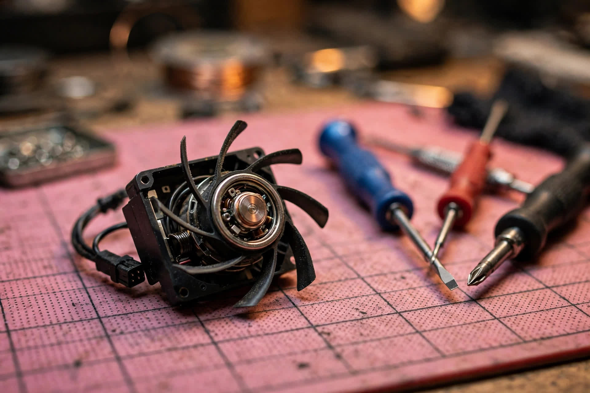
Scope: this guide covers only the mechanical layer of fan motors and bearings
This guide covers only the mechanical layer of laptop fan motors and bearings. It explains bearing types and their structural differences, including sleeve bearings, ball bearings, improved sleeve bearings, fluid dynamic bearings, and magnetic levitation bearings, together with their wear mechanisms, motor starting torque and rotational resistance, noise and vibration characteristics, the mechanical causes of unstable speed, difficult starting, and intermittent stopping, the influence of tilt and placement angle on symptoms, the influence of temperature on lubrication and clearance, and the externally observable differences between bearing noise, fan blade noise, foreign object noise, and resonance noise. The embedded controller and pulse width modulation control and tachometer feedback layer is mentioned only as a contrast, because that layer belongs to batch 91, and the temperature sensor itself belongs to batch 90, while cooling fin blockage and motherboard power supply are also mentioned only as contrasts and are not developed in this guide. Readers of this guide only perform external observation and recording, including listening to sound, feeling vibration, recording starting behaviour, recording when symptoms appear, under what load, at what placement angle, and in cold or hot machine states, and then passing those records to professional inspection for reference. All internal inspection is left to professional inspection; readers must never disassemble the machine, remove the fan, add oil, or replace a bearing, and must never open the chassis themselves. Any judgement about which bearing has failed, and any conclusion drawn from a sound comparison table, must be left to professional inspection, and no reader should diagnose a bearing type from sound alone. The bearing type, rated speed, life rating, and starting torque of any individual laptop model are treated as unverified or as varying by model until supported by that model's original service manual or parts specification, and numbers taken from general fan products or general bearing literature are quoted in this guide only after their source character and measurement conditions are stated, and are never applied directly to one particular laptop. On charges, apart from the four confirmed reference prices stated explicitly in this guide, every other charge is subject to a written quotation after inspection, and those four prices do not represent the fee for this topic. Price reference: pricing. Inspection reference: diagnostic. Shop: Sha Tin Shek Mun, Dali Plaza, Room 1209, telephone +852 2186 8010, WhatsApp +852 6558 6806, opening hours 12:00-19:00. The Chinese shop address is also given as 沙田石門達利廣場 1209 室.
Chapter 1: Motor, bearing, blades, and mount as four interacting parts
A laptop fan looks from outside like a thin blower, but at the mechanical layer it can be divided into four parts that interact with each other. The first part is the motor, whose stator coils are energised to create a rotating magnetic field that drags a rotor carrying magnets, and the torque that the motor can provide is limited and changes with speed, being greatest at standstill and falling as speed rises, which is the starting point for understanding difficult starting. The second part is the bearing, which supports the shaft and decides whether the rotor can rotate for a long time with very low resistance and very small wobble, and the bearing is not the source of rotation but the locating structure that keeps the rotating body in the correct position, so that once the bearing leaves its correct position, the rotor path changes and sound, vibration, and speed all follow that change. The third part is the blades together with the rotor body, which are both the load and the inertial body, needing to be accelerated from standstill at starting and needing to overcome air resistance while running, so that blade weight distribution and rotational inertia directly affect starting time and the speed of speed climb. The fourth part is the mount and the fixing points to the chassis, which transmit fan vibration to the whole machine and also transmit chassis vibration back to the fan, so that the state of the mount can amplify or hide bearing vibration and mislead a reader into thinking that vibration has only one source.
Because the four parts interact, a fault in any one part produces symptoms that hide each other. Rising bearing resistance makes starting difficult and prevents speed from rising, so that a reader feels that the fan has no power, although the root cause may not be a weak motor but resistance consuming the motor torque budget. Uneven blade weight distribution imposes additional radial load on the bearing and accelerates bearing wear, so that a reader hears bearing noise although the starting point may have been a blade load problem, and the two are difficult to separate from outside. A loose mount can amplify originally slight bearing vibration into whole machine resonance, so that a reader feels that the whole machine shakes, although the bearing wear itself may not be equally severe. This mutual hiding determines the writing strategy of this guide, which is not to map one sound to one fault, but first to explain what kind of observable signal each mechanical change produces, then to explain which combinations of signals are more suggestive, and finally to explain which combinations cannot be separated at all and must be left to professional inspection. A reader should therefore record sound, vibration, starting behaviour, and speed feeling as four separate lines, and should not record only one line, because a single line will almost certainly mislead.
The torque budget is the most central mechanical concept in this guide. The maximum torque that a motor can provide at a given voltage is limited, and a manufacturer white paper states that stall torque itself carries tolerance, with the torque constant and phase resistance tolerances together producing an uncertainty of about eighteen percent in stall torque, a figure that comes from a brushless direct current motor manufacturer document, belongs to general motor principles, and is not a measured value for any particular laptop fan, nor a guarantee for that laptop. The meaning is that even brand new fans of the same model do not have exactly the same starting margin, and individual variation is itself normal. Bearing static friction, blade inertia, air load, and viscosity changes caused by temperature must all be deducted from this limited torque budget, and when wear, contamination, deformation, or low temperature viscosity growth consumes most of the budget, the fan enters a marginal state in which it sometimes starts and sometimes does not, shakes a few times before turning, or shows speed rising and falling irregularly. Marginal states are the easiest to misdiagnose, because they change with temperature, placement angle, and the length of time since the machine was last switched off, so that a test that looks normal in a shop today and a recurrence at home tomorrow does not mean that the test was wrong or that the user remembered wrongly, but that the marginal state itself is unstable.
Static friction being greater than dynamic friction is the second key concept. At the starting instant, what must be overcome is static friction and locating force, while after rotation begins, what must be overcome is the smaller dynamic friction and viscous resistance. A distributor technical article notes that double ball bearings have smaller static friction and therefore need less starting power, and conversely a structure with larger static friction is most strained at the starting instant. This principle directly explains why some fans run perfectly normally once they are turning, yet are particularly difficult to start, because the problem may not be high speed capability but the resistance peak at the starting instant. Similarly, the first start after a long period switched off is often more difficult than re-acceleration during continuous running, because the lubrication film may have been squeezed out of the contact area during standstill and redistributed unevenly, or may have become thicker because of low temperature. A reader must therefore record cold first starts and mid use speed changes as two separate situations and must not merge them, because merged records prevent inspection staff from seeing which stage has the greatest resistance.
Clearance is the third key concept. A new bearing has a designed clearance between shaft and sleeve, or between balls and raceways, which allows an oil film to exist and allows thermal expansion. Wear enlarges clearance, giving the rotor additional radial freedom, which appears as wobble, eccentricity, and vibration, while contamination, corrosion, or deformation may locally reduce clearance or even cause interference, which appears as sticking, difficult starting, and local heating. Enlargement and reduction are opposite directions, yet they can appear in succession in different stages of the same fan, with early wear enlarging clearance and increasing noise, and later contamination build up or corrosion increasing local resistance, reducing speed, and making starting more difficult. Growing louder and growing slower therefore do not necessarily move together, and a reader should track sound and speed or air flow feeling as two separate lines, because the speed and direction of change in the two lines are themselves inspection clues. Price reference: pricing. Inspection reference: diagnostic.
| Mechanical part | Role inside the fan | Externally observable signal when its state changes | What a reader can record | What a reader must not judge alone |
|---|---|---|---|---|
| Motor | Provides rotating torque that drags the rotor | Slow starting, slow speed climb, intermittent stopping | Starting time feeling, speed climb feeling, low speed stability | Whether the motor itself is damaged, torque values |
| Bearing | Locates the shaft, supports the lubrication film, limits wobble | Friction noise, periodic knocking, vibration, difficult starting | Sound character, vibration feeling, angle and temperature relationships | Which bearing type, clearance values, raceway state |
| Blades and rotor | Load and inertial body, produces airflow | Airflow noise change, air flow feeling change, rhythmic character | Airflow noise uniformity, air flow feeling, load situation | Whether blades are damaged or unbalanced |
| Mount and fixing points | Transmits vibration, fixes fan position | Resonance amplification, sound change after pressing | Placement method, desk material, change after pressing | Whether the mount is loose, fixing structure state |
Chapter 2: Bearing overview, sliding, rolling, oil film lift, and magnetic stabilisation
Bearing types must not be remembered by name alone, but by structural logic, because differences in symptoms come precisely from differences in structural logic. A sleeve bearing works by sliding, with a shaft sliding inside a sleeve and separated by a layer of lubricant. A ball bearing works by rolling, with steel balls rolling between inner and outer raceways and replacing large area sliding contact. A fluid dynamic bearing works by oil film lift, with rotation itself generating oil pressure that lifts the shaft away from the bearing surface, so that in operation there is theoretically no contact. A magnetic levitation bearing works by magnetic stabilisation, with magnetic force holding the rotor stable on its track and reducing or sharing the contact pressure between shaft and bearing. The four logics differ completely in sensitivity to lubrication, direction, temperature, and shock, so that the same phrase of growing louder can represent four different stages of deterioration in four different bearings, and a reader must not map a sound description directly to a bearing type.
A bearing manufacturer divides bearings into rolling bearings and sliding bearings, with rolling bearings using balls or rollers as rolling elements, and sliding bearings bearing shaft rotation on sliding surfaces without rolling elements. An oil containing sintered bearing belongs to sliding bearings, holding lubricating oil inside a porous sintered metal body, and is further divided into types without hydrodynamic grooves, in which shaft and bearing are in direct contact, and fluid dynamic types, in which surface texture on the bearing bore generates oil pressure and forms an oil film across the whole bearing gap so that the shaft does not contact the bearing. This classification comes from a bearing manufacturer press release and belongs to general bearing principles, while which sliding structure any individual laptop fan uses must be confirmed from that model's original specification, and this batch has not verified each laptop model one by one, so no inference from a manufacturer product line to an individual laptop model is allowed. The purpose of understanding the classification is not to enable a reader to confirm a structure by opening a machine, but to understand why symptom timelines can differ so greatly between bearings.
A fan manufacturer specification system itself proves that bearing type is not a spoken classification but a formal specification field written into a specification document. A manufacturer specification lists bearing codes, with different codes representing different bearing routes, and the same manufacturer product line contains several bearing routes at the same time, while the same series can have completely different life, noise, and direction characteristics because of a different bearing code. This point matters greatly to readers, because even two laptops that look similar and have similar fan sizes may use completely different bearings, and symptom interpretation must therefore be completely different. A general fan bearing comparison table found online can only be used to understand structural logic, and must never be used to decide which bearing a particular laptop uses, and still less to use life figures from that table to estimate how much longer a particular laptop fan can be used. Life figures depend on measurement conditions including temperature, humidity, load, continuous or intermittent running, and the life definition itself, and figures measured under different conditions cannot be compared directly.
A bearing inside a laptop fan must handle three loads at the same time. The first is radial load, namely rotor and blade weight together with centrifugal force from rotational imbalance, whose direction changes continuously with rotation. The second is axial load, namely airflow pressure and magnetic force pushing or pulling the rotor along the shaft, and because a thin laptop blower has extremely small axial space, changes in axial clearance are particularly likely to become intermittent contact sound between blades and housing, although whether blades truly touch the housing can only be decided by professional inspection and a reader must not confirm it by opening a machine. The third is moment load and misalignment, in which a shaft that is no longer concentric with its bearing seat makes the rotor rotate on an eccentric path, producing a periodic force change once per revolution, heard as rhythmic sound and felt as rhythmic vibration. Because the three loads exist together, bearing wear never appears as a single sound, but as a combined change in sound, vibration, and speed.
Life figures must always be written together with their source and conditions, and this is a firm writing rule of this guide. A life rating on a manufacturer datasheet, for example continuous running hours at forty degrees Celsius, is a statistical or guarantee definition under specified temperature, humidity, voltage, mounting direction, and load conditions. The life of the same bearing at forty degrees and at sixty degrees can differ greatly, and in real laptop use with long term high temperature, dust, frequent switching, and frequent changes of placement angle, actual behaviour differs from datasheet conditions. This guide therefore retains source and conditions whenever it quotes a life figure, and never writes such figures as a statement of how many years a fan will last. The actual bearing type of any individual laptop model must be confirmed from that model's official service manual or parts specification, and this batch has not verified each laptop model fan bearing type one by one, a point that is listed in the unverified list, so that any part of the text that touches an individual model must retain an unverified marking.
| Bearing logic | One sentence structural explanation | Contact during running | Dependence on lubrication | Direction sensitivity tendency | Temperature sensitivity tendency |
|---|---|---|---|---|---|
| Sleeve sliding | Shaft slides inside an oil containing sleeve | Large area sliding, separated by an oil film | Extremely high, the oil film is the load bearing itself | Fairly sensitive, gravity affects lubricant distribution | Fairly sensitive, high temperature accelerates loss |
| Ball rolling | Balls roll between inner and outer raceways | Point or small area rolling contact | Medium, grease sealed inside the bearing | Fairly low, any direction can run | Stronger, high temperature adaptation better |
| Fluid dynamic | Hydrodynamic grooves generate oil pressure lifting the shaft | No contact when speed is sufficient | Extremely high, oil film completeness decides everything | Generally better, oil film generated by rotation | Two sided, through viscosity at cold and hot ends |
| Magnetic levitation | Magnetic force stabilises the rotor on its track | Reduced or shared solid contact | Depends on design, auxiliary structure still needs lubrication | Generally better, depends on magnetic circuit design | Magnetic performance changes with temperature, curve unverified |
| Improved sleeve | Sleeve with grooves or improved oil path sealing | Sliding mainly, lubricant distribution more even | High, but loss starts later | Better than standard sleeve | Better than standard sleeve, still limited by lubrication temperature |
| Hybrid structure | One end ball, one end sleeve | One end rolling, one end sliding | Mixed characteristics of both ends, specification decides | Between the two, varies by model | Between the two, varies by model |
Chapter 3: Sleeve bearings, the simplest structure and the most dependent on one oil layer
The structure of a sleeve bearing can be stated in one sentence, namely a shaft sliding inside a cylindrical sleeve, with a layer of lubricant between shaft and sleeve. The sleeve itself is often an oil containing sintered metal, holding lubricating oil inside a porous sintered metal body, or a sealed design that keeps lubricant in the gap between sleeve and shaft. The rotor is mounted on the shaft, and axial position is held by clips and pressure seals. There are no balls, no raceways, and no cage, so that part count is smallest and manufacturing cost is lowest. Precisely because the structure is simple, whether a sleeve bearing is good or bad depends almost entirely on two things, namely the machining precision of sleeve and shaft, and whether lubricant is still present and still effective. Machining precision decides initial clearance and oil film thickness, while lubricant state decides whether the oil film can be maintained for a long time, and a change in either one makes the quiet advantage disappear first.
A new sleeve bearing is quiet for two reasons. The first is that sliding contact spreads over a large area and disperses pressure, while the lubrication film itself damps vibration, so that fine vibration does not easily become sound directly. The second is that there is no periodic impact of balls rolling on raceways and no cage sound, so that at low and medium speeds a sleeve fan when new is often among the quietest in its class. This quietness is conditional, however, because it assumes a complete lubrication film, normal clearance, and centred shaft alignment, and once any one of these changes, the quiet advantage disappears first and becomes various friction sounds. This is why a change from previously quiet to gradually louder is the most common external narrative of sleeve bearing ageing, not because the motor suddenly changed, but because lubrication and clearance conditions changed. When recording, a reader should state the timeline of quiet to loud, whether it was sudden or gradual, whether it appears only at starting or throughout running, because the timeline itself is an inspection clue.
A distributor article organising a manufacturer technical topic states that the advantages of sleeve bearings are simple structure, lower cost, and extremely small vibration before wear, while the disadvantage is that wear accelerates after lubricant loss. Lubricant inside a sleeve bearing has three functions, namely separating surfaces, locating the shaft centre, and limiting friction and wear, while also providing a certain vibration damping effect. All three functions depend on the same oil film, so that once the film thins, all three weaken together rather than only one weakening. Sleeve bearing deterioration therefore often appears as several symptoms together, namely louder sound, more obvious vibration, and more difficult starting, which are not three independent faults but three expressions of the same oil film failure. If a reader records only sound, inspection staff cannot see this simultaneity, and simultaneity itself is an important clue pointing towards the sleeve layer, so that sound, vibration, and starting must be recorded together.
The axial retention structure of a sleeve bearing also deserves explanation. Axial position is held by clips and seal structures, and these structures themselves age, with seal ageing making lubricant migration or loss easier, and clip wear enlarging axial clearance and increasing the axial freedom of the rotor. Enlarged axial clearance may appear externally as intermittent contact feeling in sound, or as an axial component in vibration, but a reader cannot distinguish from outside whether radial or axial clearance has enlarged, and still less measure a clearance value. These details belong to professional inspection, and a reader only needs to record the trend of sound and vibration change, and must not try to infer a specific clearance value or which direction of clearance is at fault from outside, because any such inference would be an unverified guess, and writing it into a record would mislead the inspection direction.
A sleeve bearing inside a thin laptop blower faces harsher conditions than a general fan. A laptop fan is extremely small, its bearing is also extremely small, the absolute amount of lubricant is very small, and a small loss or contamination therefore has a proportionally larger effect on oil film thickness. At the same time, laptop use changes greatly, with frequent temperature rises and falls, frequent placement angle changes, and many switching cycles, all of which affect lubricant distribution and oil film stability. It must be stressed, however, that this paragraph states general principles and relative relationships, and is not a measured comparison for any particular laptop fan, because the sleeve size, lubricant type, and seal design of individual laptop fans must be confirmed from that model specification, and this batch has not verified them one by one, so that general fan sleeve behaviour must not be applied directly to laptops. The purpose of understanding harsh conditions is to understand why slight lubricant change can already produce audible symptoms, and not to enable a reader to decide that a particular laptop must be using a sleeve bearing.
| Sleeve bearing state | Oil film state | Friction mode | External sound tendency | External vibration tendency | Starting tendency |
|---|---|---|---|---|---|
| New, film complete | Thick film, full hydrodynamic mode | Friction coefficient extremely low, general range about 0.001 to 0.005 | Extremely quiet, airflow sound mainly | Almost imperceptible | Smooth starting |
| Film thinning | Mixed film, surface asperities intermittently contact | Friction coefficient rising to about 0.02 to 0.08 | Slight friction sound occasionally at starting or low speed | Slight, intermittent | Slightly delayed starting, slight low speed shaking |
| Film essentially gone | Boundary film, direct contact mainly | Friction coefficient about 0.08 to 0.14 or higher | Continuous dry friction sound or squeal | Obvious, rhythmic | Difficult starting, rising chance of intermittent stopping |
| Clearance enlarged with eccentricity | Film difficult to hold centred | Contact pressure concentrated, local wear accelerates | Rhythmic friction or knocking feeling | Perceptible, changes with speed | Starting resistance further increased |
| Contamination entered | Film broken by particles, continuity interrupted | Scratching accelerates, film harder to maintain | Rushing sound with intermittent scratching feeling | Intermittently worse | Depends on contamination level, unverified |
Chapter 4: Sleeve wear in three lines, lubrication failure, clearance growth, and dust entry
The leading wear mechanism of sleeve bearings is lubrication failure. Lubricant leaves its working position in three ways, namely evaporation, which is faster at higher temperature, with several sources agreeing that high temperature accelerates lubricant loss, although a statement in one guide about lubrication system efficiency above seventy degrees Celsius is only that guide description and must never be generalised into a universal failure temperature for all sleeve fans, and this guide quotes it only with that limitation; migration, in which lubricant slowly moves away from the load zone along the shaft or seal edge, with placement direction affecting migration direction, a point developed further in the angle chapter; and deterioration, in which lubricant changes viscosity and chemical character after heating, dust contamination, and long term shearing, and loses its ability to carry an oil film. Lubrication failure is not a binary switch of oil present or oil absent, but a continuous deterioration path from full film, through mixed film, towards boundary film. External behaviour is therefore gradual, beginning as slight friction sound occasionally at starting or low speed, then appearing across more speed ranges, and finally appearing most of the time. When recording gradual change, a reader should state which speed range showed sound first and which range showed it last, because the order of range expansion is itself the timeline of oil film deterioration.
The direct consequence of lubrication failure is that the sleeve bore and shaft surface begin to rub directly, with material removed little by little. Removal is not uniform, because the load direction side wears more, so that the sleeve bore gradually changes from circular to slightly elliptical or unevenly worn, and radial clearance between shaft and sleeve therefore grows. This elliptical change is described both in a distributor article and in user discussion, in which a worn copper sleeve bore is no longer round, so that the shaft centre shakes and rubs inside the elliptical bore, producing humming sound and large vibration. Once clearance grows, the shaft is no longer stably held at the centre by the oil film, but can wobble within the clearance range, so that the rotation path changes from centred to eccentric plus wobbling. Eccentricity itself concentrates load on a smaller contact area and accelerates local wear, forming a vicious circle. Bearing manufacturer logic applies fully here, because poor fitting, bearing ring deformation, and clearance change all move the shaft away from its correct position and produce noise and vibration at high speed. For a reader, enlarged clearance translates externally into sound changing from uniform airflow sound to rhythmic friction or knocking feeling, vibration changing from almost imperceptible to fine vibration that can be felt with a hand on the machine placed on a desk, and such vibration often changing with speed, with higher speed producing greater centrifugal force from eccentricity and larger vibration and sound amplitude, until resonance amplification appears in some speed range, with resonance identification covered in a later chapter.
Dust harms sleeve bearings in two ways. First, dust itself is abrasive, because fine particles entering the gap between shaft and sleeve scratch sliding surfaces, and scratches break oil film continuity and cause more direct contact. Second, dust contaminates lubricant and blocks the micropores of oil containing sintered metal, reducing oil storage and oil release capability. A sleeve bearing maintenance principle states that minimum oil film thickness is extremely small, so that impurities in oil can greatly accelerate wear, and if foreign matter is large and plentiful, a bearing can fail quickly, with airborne contaminants being an important source of abrasive material. For laptop readers, the external clue of dust entry is not seeing dust, but the relationship between symptoms and use environment, namely long term use in a dusty environment, long term high fan speed, and gradually worsening rather than suddenly appearing symptoms. It must be stressed that fin blockage and air path dust belong to another layer and are not developed in this guide, and this section covers only the mechanical consequence of dust entering the bearing gap itself, so that the two must not be confused. When recording environment, a reader should state dust, fibre, and hair conditions, for example fabric surroundings, carpet, or pets living in the same room, as background information for inspection, but not as a diagnosis of contamination.
Sleeve fan failure sometimes arrives suddenly, and this point must be specially reminded. A review media guide states that sleeve fans sometimes fail suddenly, without obvious warning beforehand, occasionally with prior squeal or slowing that is difficult to distinguish from other noises. A fan that has been silent and then suddenly stops therefore cannot be used to exclude a sleeve bearing problem, and recording the suddenness itself is important information. The mechanism of sudden deterioration can be understood as slow wear in the early stage, accelerated wear after eccentricity grows in the later stage, or a sudden oil film rupture at a critical point, jumping from mixed film to boundary film, so that symptoms change from slight to obvious within a short time. If a reader records that sound appeared occasionally three months ago and now appears almost every time the machine is switched on, that timeline is itself valuable inspection information, far more valuable than only saying that it is loud. Conversely, if symptoms have remained stable without an expansion trend, a reader should record stability honestly rather than exaggerating it into deterioration, because a stable record also has inspection value and helps inspection staff judge deterioration speed.
In summary, the external profile of sleeve bearing wear is quiet at first, dry friction sound or slight squeal first at starting and low speed in the middle stage, sound expanding to more speed ranges with rhythmic character in the later stage, gradually perceptible vibration, rising starting resistance shown as delayed starting or intermittent stopping, and symptoms obviously affected by temperature and placement angle. This profile is only a tendency description and not a diagnostic standard, because later stage ball bearings, fluid dynamic oil film rupture, blade problems, and resonance problems can all show part of a similar profile. When using the profile, a reader should compare five dimensions in recorded observations, namely sound character, vibration, starting behaviour, temperature relationship, and angle relationship, and only when several dimensions together point towards a sleeve tendency is it worth stating that tendency in a repair summary, rather than concluding from a single dimension. Price reference: pricing. Inspection reference: diagnostic.
| Sleeve wear mechanism | Starting point | Middle process | Later result | Earliest external signal | Recording focus |
|---|---|---|---|---|---|
| Lubricant evaporation | High temperature accelerates base oil loss | Film thins, enters mixed film | Boundary contact, wear rises sharply | Slight friction sound at starting or low speed | Cold and hot difference, change after long high load |
| Lubricant migration | Lubricant moves away from load zone | Load side film insufficient | Uneven wear, clearance grows | Sound heavier at one placement angle | Flat, tilted, and side placement comparison |
| Lubricant deterioration | Heating, shearing, contamination change character | Viscosity and load capacity fall | Film difficult to maintain | Sound range gradually expands | Which speed range expands to which range |
| Clearance growth | Direct friction removes material | Bore becomes elliptical, eccentric wobble | Load concentrated, vicious circle | Rhythmic friction or knocking feeling | Whether rhythm changes with speed |
| Dust entry | Particles enter the gap | Scratches break film, block oil storage pores | Oil release capability falls, wear accelerates | Rushing sound with intermittent scratching feeling | Use environment background, gradual or sudden |
Chapter 5: Ball bearings, rolling instead of sliding, at the cost of another kind of noise
The structure of ball bearings is completely different from sleeve bearings, because several precision steel or ceramic balls are placed between inner and outer rings, separated and spaced by a cage, and rolling on inner and outer raceways, so that rotating and fixed parts are connected by rolling contact instead of sliding contact. Common specification forms for laptop and small fans include double ball, single ball, and single ball plus single sleeve hybrid forms, with double ball using two ball bearings to support the two ends of a shaft and giving better rigidity and alignment, and single ball plus single sleeve using one end rolling and one end sliding as a compromise between cost and performance. How the other end of a single ball design is supported, and how clearance is distributed, must be confirmed from individual model specifications, and this batch has not verified hybrid structure details for each laptop fan, so that point is listed as unverified. Ball bearings are usually sealed by covers or seals that keep grease inside the bearing, and seals also help block dust and moisture, although seals themselves age, and after ageing their blocking capability falls and the chance of contamination entry rises.
The friction mechanism of rolling contact differs from sliding, because balls and raceways theoretically meet at a point or small area, so that rolling resistance is far lower than large area sliding friction. Precisely because rolling itself does not need a continuous oil film to lift the shaft, ball bearings are less sensitive to lubricant loss than sleeve bearings, and have no sleeve type limitation that depends on gravity distributing lubricant, so that they can be mounted in any direction without significantly affecting performance, a point on which several sources agree. The same applies to temperature, because ball bearings can maintain longer life at higher temperature, with sleeve life falling far more than ball life as temperature rises, and ball bearings being quieter than aged sleeve bearings at high speed. The costs of these advantages are more complex structure, higher cost, greater sensitivity to shock, and possibly being slightly louder when new. Ball rolling sound on raceways and cage sound can be audible in a quiet environment, especially as slight regular sound at low speed, and such slight rolling sound can also appear on a normal new bearing, so that hearing slight rolling sound must never be taken as proof of failure.
A fan motor article states that fan motors usually use a pair of bearings separated by a spring, with the spring helping to handle tilt caused by rotor weight. The spring provides preload, keeping the rotor in position at different angles, and if preload is insufficient or the spring fatigues, rotor tilt under gravity grows larger, contact pressure distribution between shaft and sleeve becomes more uneven, and wear accelerates. A magnetic levitation structure, by contrast, uses magnetic force to support rotor weight and reduces the direct effect of gravity on the bearing. These structural differences explain why different laptop fan models can differ greatly in angle sensitivity, with the same tilted placement having no effect on one model and obvious symptoms on another. Whether an individual model has spring preload or magnetic levitation structure must be marked as unverified without an original specification, and a reader must not infer it from appearance or brand.
Ball bearing load capacity is relatively limited, and vulnerability to shock damage is higher than for other bearings, a point from an electronic component distributor forum article. Another source also states that ball fans are less suited to environments with frequent movement vibration, while sleeve bearings are more vibration tolerant. When this point is compared with laptop use, care is needed, because a laptop is itself a frequently moved device, but ball bearing size, preload, sealing, and chassis damping design of a laptop fan are all decided by the whole machine design of the laptop manufacturer, and this batch has not verified whether fans of individual laptop models are particularly prone to dents or cage problems because of movement vibration. This guide therefore states only the general principle, namely that shock is a known damage source for ball bearings, and that noise appearing only after a fall or strong impact is worth marking with its time relationship in a record, rather than writing an unverified statement that frequent carrying must make ball bearings fail easily. The recording method for time relationship is to state the approximate date of impact or fall, the approximate date of first symptom, and how long passed between them, and not only to write that the machine was dropped and therefore must be damaged by the drop.
A new ball bearing already having slight uniform rolling sound belongs to the normal range, and defining this normal range matters greatly to readers, because many misdiagnoses begin by treating normal rolling sound as a fault. Normal rolling sound is characterised by uniformity, continuity, stable loudness, smooth change with speed, and no sudden knocking or friction jump. After wear, sound departs from this uniform baseline, with periodic change, knocking feeling, loudness jump, or change that is particularly obvious only in one speed range. When recording, a reader should use the previous uniform baseline as a comparison reference, stating what is different now compared with before, rather than only saying that it is loud now. A comparative record such as uniform airflow sound under the same program and placement before, and now intermittent knocking feeling, is far more reliable than an absolute description, and is the record format that inspection staff need most.
| Ball structure form | Structural meaning | Rigidity and alignment tendency | Cost tendency | Noise tendency | Items to verify |
|---|---|---|---|---|---|
| Double ball | One ball bearing at each end | Better, supported at both ends | Higher | Slight uniform rolling sound | Preload and sealing of individual models |
| Single ball | Only one ball bearing, other end depends on design | Depends on other end design, unverified | Middle | Depends on design | Support method of the other end |
| Single ball plus single sleeve | One end rolling, one end sliding | Between double ball and pure sleeve | Middle | Mixed characteristics, sounds of both endscombined | Clearance distribution of both ends |
| Ceramic ball version | Rolling elements made of ceramic material | Depends on design | Higher, individual models unverified | Depends on design | Whether individual laptop models use it, unverified |
Chapter 6: Ball wear in five lines, spalling, grease, clearance, dents, and cage
The most representative wear mechanism of ball bearings is not thinning, but fatigue spalling. Balls and raceways bear periodically changing contact stress once per revolution, and after stress cycles accumulate to a certain number, surface metal of raceways or balls develops fine cracks and then flakes off in scales. A bearing manufacturer failure analysis manual stresses that once spalling appears it continues to deteriorate until the bearing cannot be used, with a progression that can be divided into initial spalling, progression, severe spalling causing high vibration, and fatigue fracture. The consequence of spalling is a chain reaction, because a spalling pit makes rolling no longer smooth, balls produce impact when passing the pit, impact accelerates fatigue and wear of surrounding material, and at the same time breaks lubrication film continuity and causes more direct contact. Externally this translates into sound changing from uniform rolling sound to periodic clicking or grinding feeling, with a period related to speed, so that impact frequency changes when speed changes, and vibration changing from slight to perceptible periodic vibration. A bearing manufacturer abnormal sound table maps crunching sound to regular scratching on raceway surfaces, irregular scratching on balls, dust contamination, and bearing ring deformation, maps growling sound to scratching on raceways, balls, or rollers, and maps buzzing to roaring sound to resonance, poor fitting, bearing ring deformation, raceway and ball vibration, and dents. These categories remind writers not to use only the word loud, but to record whether sound changes pitch with speed, whether it is continuous, and whether it is rhythmic.
Although ball bearings are less sensitive to lubricant loss than sleeve bearings, grease remains a key variable for their life. Manufacturer guides agree that insufficient lubrication, wrong lubricant type, deteriorated lubricant, and excessive lubricant can all cause high temperature, noise, and early damage. Grease deterioration paths include accelerated oxidation at high temperature, consistency change after long term shearing, contamination or emulsification by dust and moisture, and grease loss after seal damage. When lubrication is insufficient, balls inside the cage collide, and a manufacturer abnormal sound table maps low speed obvious and highly continuous trembling sound to cage pocket impact and insufficient lubrication, with sound particularly obvious at low speed. After grease deteriorates to a certain level, ball and raceway contact changes from full film towards mixed or even boundary states, wear speed rises, and fatigue spalling is then accelerated. Unlike sleeve bearings, ball bearing grease is sealed inside the bearing, so that a reader cannot observe grease state from outside, and must certainly not open a bearing to replenish it, because external work is limited to recording how sound and vibration change with temperature, speed, and time.
Radial clearance of ball bearings is a design parameter, because too small clearance increases rolling resistance, heating, and turning difficulty, while too large clearance worsens shaft location and increases vibration and noise. Clearance grows because of wear, with material loss from raceways and balls, and can also change because of poor fitting, thermal expansion, and shaft bending, which belong to manufacturing and inspection layers, so that a reader can only infer from symptoms that clearance may have changed and cannot measure it. Brinelling is another damage form, in which excessive static load or shock presses dents matching ball shape into raceways, so that balls produce one impact each time they pass a dent, with sound and vibration highly periodic, and a manufacturer abnormal sound table lists dents as one cause of buzzing to roaring sound. Cage damage comes from insufficient lubrication, rolling element squeezing, and bearing seat tilting, and once a cage deforms or breaks, ball spacing is no longer uniform, sound becomes irregular, and vibration suddenly worsens. Dust contamination harms ball bearings through denting and scratching, because hard particles pressed by balls into raceways cause small dents and scratches, which then become starting points for fatigue cracks. Ball bearing wear is therefore often not a single mechanism, but a chain of contamination, scratching, lubricant deterioration, fatigue spalling, clearance growth, and vibration growth, and an early clue on any link of the chain is worth recording.
Bearing damage can be divided by timing into early failure, occasional failure, and wear failure, a timing classification from a bearing manufacturer technical guide. Early failure often comes from improper handling, improper mounting, poor assembly, incorrect or insufficient lubrication, or insufficient consideration of running environment or temperature at the design stage. Occasional failure may relate to individual events, such as shock, contamination entry, or sudden load change. Wear failure is the result of long term accumulation, with fatigue spalling and material loss belonging to this class. The practical meaning of timing classification is that a reader recording when symptoms first appeared, their time relationship with earlier events, and their deterioration speed, is itself providing clues to distinguish early, occasional, and wear failure. For example, symptoms suddenly appearing after a larger impact make shock related occasional failure worth attention by inspection staff, while symptoms gradually worsening without a clear event starting point make wear more worth attention. These are only tendencies, not diagnoses, and inspection must still exclude control and temperature sensor layers one by one.
In summary, the external profile of ball bearing wear is slight uniform rolling sound within the normal range when new, sound becoming buzzing, growling, or periodic grinding that changes pitch with speed after wear, possible cage trembling sound at low speed, periodic and perceptible vibration, rising starting resistance that is usually not as completely immovable as a severely lubricant dried sleeve bearing, a statement that is only a tendency description and not a diagnostic standard. The temperature pattern of symptoms is more complex than for sleeve bearings, because grease viscosity is higher at low temperature, so that low temperature starting sound may be more obvious and may ease slightly after warming up, a pattern different from the common sleeve pattern of heavier symptoms when hot, so that cold and hot performance must be recorded separately and must not be applied to each other. If a reader applies a sleeve temperature pattern to a ball bearing, the reader may wrongly think that easing when hot means that there is no problem, although low temperature starting sound itself is already a clue that must be recorded separately.
| Ball wear mechanism | Mechanical process | Sound tendency | Vibration tendency | Starting and speed tendency | Reversibility tendency |
|---|---|---|---|---|---|
| Fatigue spalling | Cyclic stress causes surface cracks and flaking | Periodic grinding or clicking, frequency changes with speed | Periodic impact vibration, worsening as spalling expands | Speed fluctuation, intermittent resistance rise | Tends to be irreversible, spalled surface cannot become smooth again |
| Grease deterioration | Oxidation, shearing, contamination, emulsification, loss | Low speed trembling sound, later expanding to more speeds | Slight to obvious, worsening with deterioration | Low speed instability, slightly difficult starting | Depends on level, inspection decides |
| Clearance change | Wear enlarges clearance, or fitting and thermal expansion change it | Uniform rolling sound becomes loose or louder | Location worsens, vibration amplitude grows | Turning resistance abnormal, sometimes large sometimes small | Depends on cause, inspection decides |
| Brinelling dents | Static load or shock presses dents into raceways | Highly periodic impact sound | Highly periodic impact vibration | One resistance peak per revolution | Tends to be irreversible |
| Cage damage | Insufficient lubrication, squeezing, tilting cause deformation or breakage | Irregular knocking sound, intermittently worse | Suddenly worse, irregular | Speed instability worsens | Tends to be irreversible, inspection decides |
| Contamination denting | Hard particles pressed into raceways cause dents and scratches | Gradually appearing periodic sound | Gradually worsening | Gradually appearing resistance fluctuation | Dents themselves tend to be irreversible |
Chapter 7: Improved sleeve and hybrid structures, improvement inside one family is not another bearing
Rifle bearings and Superflo bearings represent a route that does not leave sleeve principles but improves lubricant management, and understanding them helps readers see why a bearing cannot be judged by the word sleeve alone. A rifle bearing adds spiral grooves to the sleeve bore, and the grooves act like a pump that returns lubricant from an oil storage area to the top of the shaft and the load zone, making lubricant distribution more even, reducing friction, and therefore giving life close to ball bearings and smaller direction limitation than a standard sleeve. A Superflo bearing achieves a similar effect through redesigned sealing and oil flow paths, reducing lubricant loss, lowering friction and noise, giving better low speed acoustic performance than double ball bearings, and giving good shock resistance. The common lesson of both is that wear mechanisms remain lubricant management and clearance, except that improved design postpones the starting point of the chain from lubricant loss to clearance growth to eccentricity to noise. For readers, the symptom profile of improved sleeve bearings is similar to that of standard sleeve bearings, but appearance time may be later and sound deterioration speed may be slower. Conversely, if a fan marked as an improved sleeve type already shows typical sleeve wear sound within a short time, it is more worth recording use environment, such as high temperature, dust, and long term high speed, as an inspection clue, rather than directly concluding that the design is faulty. Whether any individual laptop fan uses rifle or Superflo structure must be confirmed from that model specification, and this batch has not verified them one by one, so that point is listed as unverified.
A Superflo manufacturer datasheet contains a figure worth special explanation, namely that the series is marked as having a minimum life of fifty thousand hours at forty degrees Celsius, with a wider applicable temperature range. This figure must be understood together with its conditions, because forty degrees is a measurement condition and not the actual internal temperature of a laptop, and the definition of a life guarantee differs from a general approximate figure, and still less can the figure be applied directly to any particular laptop fan. The point is not the fifty thousand figure itself, but that improved sealing and oil path design within the same sleeve family can significantly change noise and life performance, so that not all sleeve bearings can be treated as the same level. If a reader knows the bearing marking of a laptop fan in a repair summary, the reader should state the marking source, for example an original parts specification or service manual, but if the marking source is only an online general comparison table, the reader should state that it is unverified, and must not write a general table marking as the specification of that particular machine.
A hybrid single ball plus single sleeve structure deserves a separate section, because its symptoms may carry characteristics of both bearing types at the same time and make identification more difficult. With one end rolling and one end sliding, one end wears by spalling and grease deterioration, while the other end wears by lubricant drying and clearance growth, and after the sounds of the two ends arecombined, a reader may hear a mixed sound that has both rolling periodic feeling and sliding dry feeling. The deterioration speeds of the two ends may also differ, with one end failing first while the other end remains normal, so that symptoms may be obvious only in one speed range or at one angle. When recording hybrid structure symptoms, a reader needs even more separation of speed range, angle relationship, and temperature relationship records, because a single dimension record easily captures only one end characteristic and misleads inspection staff into thinking that there is only one kind of wear. How the other end of a hybrid structure is supported and how clearance is distributed must be confirmed from individual model specifications, and this guide does not add general figures for hybrid structures.
Life approximate figures for improved sleeve bearings differ greatly between sources, and this difference itself is a teaching point. A manufacturer guide describes rifle bearing life as about eighty thousand hours, while a Superflo bearing at forty degrees is marked as a minimum of fifty thousand hours, and these two figures have completely different measurement conditions, life definitions, and temperature conditions, so that they must never be compared directly, and it must never be said that rifle bearings must live longer than Superflo bearings. General fan guide life approximate figures, for example sleeve about thirty thousand to forty thousand hours and ball about sixty thousand to seventy five thousand hours, are all approximate figures under specific conditions, and figures from different manufacturers under different measurement conditions must not be mixed. When a reader sees two life figures online, the reader should first ask what the measurement conditions are, what the life definition is, and what the temperature is, and if these three questions cannot be answered, the figures have no comparative meaning. This principle applies to all life figures quoted in this guide, and a reader should use the same standard to examine other articles in the future.
Another lesson of improved routes is that bearing selection is always a trade off, and not a case of more expensive being better or newer being better. The trade off for sleeve bearings is quietness and low cost against sensitivity to lubrication and direction, the trade off for ball bearings is wide direction and temperature adaptation against shock sensitivity and slightly louder sound when new, the trade off for fluid dynamic bearings is high speed low vibration against sensitivity to starting and low speed, and the trade off for magnetic levitation is low vibration and low noise against sensitivity to track stability. The trade off for improved sleeve bearings is to retain sleeve advantages while postponing the starting point of lubricant failure through grooves or oil path design, at the cost of higher manufacturing cost and greater structural complexity, while still being limited by lubricant temperature. Which bearing a laptop manufacturer selects for a model is the result of whole machine design trade offs, including thickness, speed, noise target, cost, and supply chain, and a reader does not need and should not use bearing type to judge backwards whether a manufacturer choice was correct, but only needs to understand that different trade offs bring different symptom timelines, so that records can be made with the right focus.
| Improved route | Improvement method | Weakness addressed | Weakness still retained | Symptom timeline tendency | Verification status for individual models |
|---|---|---|---|---|---|
| Rifle grooves | Spiral grooves in sleeve bore pump lubricant | Uneven lubricant distribution | Still limited by lubricant temperature and loss | Later appearance, possibly slower deterioration | Unverified whether individual laptop models use it |
| Superflo sealing and oil path | Redesigned sealing and oil flow paths | Lubricant loss and low speed noise | Still limited by lubricant temperature | Better low speed performance, postponed deterioration start | Figure limited to that series, forty degree condition |
| Magnetic stabilisation assistance | Magnetic force stabilises rotor track | Contact pressure and wobble | Auxiliary structure still ages | Extremely quiet baseline, slight change easier to notice | Unverified whether full levitation or magnetic assistance |
| Hybrid ball and sleeve | One end rolling, one end sliding | Extreme weakness of a single structure | Wear modes of both endscombined, harder to identify | Mixed sound, more complex speed and angle relationships | Unverified clearance distribution details |
Chapter 8: Fluid dynamic bearings, lifted by an oil film, most critical at starting and stopping
Fluid dynamic bearings belong to sliding bearings, but the key difference from standard sleeve bearings lies in surface texture on the bearing bore, usually herringbone or spiral hydrodynamic grooves. When the shaft rotates, grooves drag lubricating oil into a narrowing wedge gap between shaft and bearing, viscous shearing generates pressure that lifts the shaft, so that shaft and bearing are completely separated when running speed is sufficient. A bearing manufacturer explanation is most precise, namely that an oil containing sintered bearing without hydrodynamic grooves has shaft and bearing in direct contact, while a fluid dynamic bearing with hydrodynamic grooves uses oil pressure generated by surface texture to form an oil film across the whole bearing gap so that the shaft does not contact the bearing. A motor manufacturer positions the value of fluid dynamic bearings first in vibration control, because technology transferred from hard disk spindle motors aims to maintain low vibration at high speed, with design reviewing magnetic circuit layout, resin or metal parts, shaft diameter, and other hard disk spindle motor design decisions, and using computer aided engineering to optimise blade size and shape to balance airflow and noise at a specified air volume. The lesson for laptop writing is that the value of fluid dynamic bearings lies first in vibration control, and not only in the adjective quiet.
The wear distribution of fluid dynamic bearings differs from sleeve and ball bearings. When running speed is sufficient and the oil film is complete, shaft and bearing have no solid contact, and theoretically there is no wear. Oil film pressure is a function of speed, however, so that at standstill and extremely low speed the oil film is not established, the shaft rests at the bottom of the bearing and is supported by residual oil film or direct contact, surface asperities touch directly, and this belongs to boundary lubrication, with the greatest friction and wear concentrated in this stage. After speed rises, the oil film is established, full film lubrication begins, and friction and wear fall sharply. When stopping, the process reverses, with speed falling, oil film pressure falling, and the shaft returning to contact. Fluid dynamic bearing wear is therefore not a linear relationship of more use meaning more wear, but a relationship in which switching cycles and low speed running time account for a disproportionate share. For laptop readers, this principle explains a seemingly contradictory phenomenon, namely that a fluid dynamic fan running continuously for a long time may remain quiet for a long time, while a fan frequently switched on and off and frequently switching between low speed and stopping may show starting friction sound earlier. Whether frequent switching truly accelerates wear of an individual laptop fluid dynamic fan must be confirmed from that model design and testing, and this guide states only the general principle without making an individual claim.
Fluid dynamic bearing wear mechanisms can be summarised into four paths. The first is oil film rupture, in which lubricant loss, deterioration, viscosity fall because of high temperature, sudden load increase, or sudden speed fall can make oil film thickness fall below surface asperity height, so that shaft and bearing contact again and produce scratching. The second is contamination, in which dust particles entering the oil film gap scratch hydrodynamic grooves on the bearing bore and the shaft surface, and once grooves are damaged, oil pressure generation capability falls, the oil film becomes harder to maintain, and a vicious circle forms. The third is groove wear itself, in which every starting and stopping boundary contact causes slight wear on groove edges, and after accumulation, hydrodynamic efficiency falls, the speed needed to establish an oil film rises, and the tendency appears that a higher speed is needed before running becomes smooth. The fourth is chemical deterioration and loss of lubricating oil, which is the same as for sleeve bearings, with high temperature, long term shearing, and contamination making lubricating oil lose load bearing capability, but fluid dynamic bearings demand oil film completeness more than standard sleeve bearings, because their non contact depends entirely on the oil film, so that once the film is incomplete, the wear mode jumps from almost zero wear to direct contact wear, and symptom change may be more sudden than gradual.
Direction adaptation of fluid dynamic bearings is generally better than that of standard sleeve bearings, with a manufacturer guide stating that they can be mounted in any direction without downgrading, because the oil film is generated by rotation itself and does not depend on gravity keeping lubricant on one side. This does not mean that direction has no effect at all, because axial load direction and the effect of gravity on the shaft rest position still change the initial contact position at starting and the oil film establishment process, and individual design differences must be confirmed from manufacturer specifications. Temperature affects fluid dynamic bearings mainly through viscosity, with rising temperature lowering viscosity, thinning the oil film, and lowering load capacity, and falling temperature raising viscosity, increasing starting resistance, and slowing oil film establishment. The temperature pattern of fluid dynamic bearing symptoms may therefore be two sided, with slow cold starting and thin oil film under hot high load, and both must be recorded separately. Unstable speed has a special meaning in the fluid dynamic context, because if the oil film is at the boundary between establishment and rupture in one speed range, the rotor swings between being lifted and falling back into contact, appearing as speed sometimes fast and sometimes slow, sound sometimes smooth and sometimes rough, and vibration sometimes present and sometimes absent, and this intermittency itself is a clue of oil film instability, although the same intermittency can also be caused by the control layer, so that this guide provides only one possible mechanical explanation and does not make an exclusive diagnosis.
The external profile of fluid dynamic bearing wear is extremely quiet and low vibration when healthy, early problems mostly appearing at starting and stopping stages as delayed starting, brief friction sound at starting, and sound change before stopping, mid stage instability in the low speed range with relatively smoother high speed, and later difficulty maintaining an oil film, with sound and vibration expanding to more speed ranges and rising chance of intermittent stopping. The difference from sleeve bearings is that fluid dynamic deterioration may not be a linear pattern of growing louder, but a pattern in which low speed and starting stages fail first while high speed can remain for some time, and this asymmetry is the point most worth writing down in a record. When recording, a reader should write low speed performance and high speed performance separately, because if low speed is poor and high speed is good, inspection staff will give priority to oil film establishment related mechanical clues, while if low speed is good and high speed is poor, the inspection direction will be completely different, and the two must not be merged into one phrase of unstable speed.
| Fluid dynamic stage | Oil film state | Contact state | Friction tendency | External tendency | Recording focus |
|---|---|---|---|---|---|
| Standstill | No oil pressure, shaft rests at the bottom | Direct contact or residual film support | Static friction greatest | Starting resistance peak | Cold first start behaviour |
| Extremely low speed | Film beginning to establish, not fully lifting | Asperities intermittently contact, mixed film | Friction fairly high | Brief friction sound, low speed shaking | Sound and stability in low speed range |
| Medium and high speed | Film complete, full film lubrication | Completely no contact | Friction extremely low | Extremely quiet, low vibration | Whether high speed remains smooth |
| Slowing to stop | Film pressure falls with speed | Returning to contact | Friction rises again | Sound change before stopping | Sound change in stopping stage |
| Film rupture | Film thickness below asperity height | Contact again, scratching | Friction rises sharply | Symptoms may suddenly worsen | Speed and load situation before and after rupture |
| Groove damage accumulation | Hydrodynamic efficiency falls | Speed needed to establish film rises | Starting and low speed friction rises | Higher speed needed before smooth running | Asymmetry of poor low speed and good high speed |
Chapter 9: Magnetic levitation and magnetic stabilisation bearings, magnetic force does not mean never wearing
The principle of magnetic levitation bearings is to use magnetic force to suspend or stabilise a rotor on its track, reducing or even avoiding solid contact between shaft and bearing. A manufacturer product description states that magnetic levitation uses a vertical magnetic attraction system to lock motor rotation on a fixed and stable track, stabilising the centre of gravity, reducing wobble and vibration, and reducing friction between shaft and bearing, and together with reinforced material and structural bearing technology, it claims to overcome the weaker heat resistance of general sleeve bearings and to achieve low vibration, low noise, and long life. A distributor summary describes magnetic stabilisation as an improvement based on magnetic rotor stabilisation, while a manufacturer guide lists magnetic levitation alongside fluid dynamic bearings as a non contact or low contact route. It must be noted that magnetic levitation on the market is not a single design, because some designs are fully levitated, with the rotor completely free of contact, while others are magnetically assisted, with magnetic force sharing load and reducing contact pressure, but with shaft and bearing still in contact or in contact at starting and stopping. Which type an individual product belongs to must be confirmed from that product official description, and all products marked as magnetic levitation must never be treated as the same structure, and still less can the words magnetic levitation be used to infer that a particular laptop fan must never wear.
Even with a magnetic levitation design, wear mechanisms do not completely disappear, but only move to other places. First, a magnetically assisted design may still bring shaft and bearing into contact at starting, stopping, or moments of insufficient magnetic force, producing boundary wear similar to sleeve or fluid dynamic bearings. Second, the stability of the magnetic circuit itself is affected by temperature, because magnetic material performance changes with temperature, magnetic force may fall at high temperature, the stable track of the rotor may change, and eccentricity and vibration therefore increase, a statement that belongs to general physics principles, while the specific temperature characteristics of individual products must be confirmed from manufacturer specifications, and this batch has not verified specific temperature curves for each magnetic levitation fan. Third, reinforced material and structural parts of the bearing itself still age, with lubricant, seals, and sleeve materials following deterioration paths similar to sleeve bearings under high temperature and dust, except possibly at a slower speed. Fourth, sensitivity of magnetic levitation design to misalignment and external vibration differs from traditional bearings, because magnetic track stability depends on magnetic circuit geometry, and external shock or chassis deformation that changes the magnetic gap changes the rotor track, and sound and vibration change accordingly. When a magnetic levitation fan produces abnormal noise, it must never be concluded directly that magnetic force has disappeared, because more likely mechanical explanations are falling track stability, reappearing contact, or beginning wear of auxiliary bearing structures, whose external appearances may be similar, and distinction must be made by professional inspection.
The external profile of a healthy magnetic levitation fan is low vibration, low noise, and smooth rotation. After wear, the external profile tends towards falling smoothness, fine vibration or rhythmic feeling that did not exist before, worsening starting and low speed performance, and sound that is no longer uniform. Because the baseline of magnetic levitation is extremely quiet, slight change is easier to notice in a quiet environment, and when recording, a reader should state under what environmental noise the sound was heard, for example a quiet room late at night compared with a daytime office, because otherwise descriptions of the same sound in different environments will appear contradictory. Environmental filtering is the first distortion of sound recording, because air conditioning sound, street sound, and other voices hide or change the feeling of fan sound, so that the same fan sounds louder in a quiet environment at night than in a noisy daytime environment, without meaning that it suddenly worsened at night. The way to resist distortion is not to ask a reader to perform professional measurement, but to ask for a comparison baseline, for example the same place, the same program, and the same placement compared with one month ago, and whether other people hear the same sound, because such comparative records are far more reliable than absolute descriptions.
Another lesson of magnetic levitation technology is that bearing load direction and size are themselves part of design. Manufacturer information stresses better shock resistance and high speed performance for magnetic levitation, but at the same time admits direction limitations, for example that a certain horizontal placement with airflow blowing upwards is not allowed. For readers, the lesson of this limitation is not to change fan mounting direction by themselves, because fan mounting direction inside a chassis is fixed, and what a reader changes is only the angle of the whole machine, and not the angle of the fan relative to the chassis. Nevertheless, changing the whole machine angle still changes the direction of gravity relative to the fan shaft, and therefore changes bearing load distribution, and this principle holds, although the actual magnitude of effect belongs to the unverified category and must never be exaggerated. When recording angle sensitivity, a reader should state specifically that sound became louder, quieter, or disappeared after changing from flat to tilted placement, and whether it returned to its original state after returning to flat placement, because reversibility itself is an important clue, with reversible angle sensitivity pointing more towards load distribution change, and irreversible angle sensitivity possibly pointing towards damage that has already occurred or foreign object displacement, with different inspection priorities.
Whether any individual laptop fan uses magnetic levitation or magnetic stabilisation structure must be confirmed from that model specification, and this batch has not verified them one by one, so that point is listed as unverified. A reader should not infer from brand, price, or promotional wording that a particular laptop must use magnetic levitation, because promotional wording and actual structure can differ greatly, and full levitation and magnetic assistance may use the same word in promotion although their mechanical structures are completely different. In a repair summary, if bearing type is unverified, it should be written directly as unverified, and not filled with a plausible type. Unverified is not a defect in a record, but an honest part of a record, because inspection staff seeing unverified will use inspection to confirm, and will not be misled in inspection direction by a wrong type. This principle applies to all unverified items in this guide, and a reader examining other articles in the future should use the same standard, treating any type claim without a stated source as unverified first.
| Magnetic levitation design type | Magnetic role | Contact during running | Contact at starting and stopping | Symptom tendency | Verification requirement |
|---|---|---|---|---|---|
| Full levitation | Magnetic force fully supports the rotor | Theoretically no contact | Depends on design, may rest when stopped | Extremely quiet baseline, symptoms only when track changes | Must be confirmed from product official description |
| Magnetic assistance | Magnetic force shares load, reduces contact pressure | Contact pressure lowered, but contact remains | Boundary contact, similar to sleeve or fluid dynamic | Auxiliary structure ageing brings contact back | Must be confirmed from product official description |
| Magnetic stabilisation plus reinforced bearing | Magnetic force stabilises track, reinforced bearing supports | Stable track, low vibration | Depends on auxiliary structure | Falling smoothness, fine vibration appears first | Must be confirmed from product official description |
| Promotional wording but structure unclear | Unverified | Unverified | Unverified | Symptoms cannot be inferred from wording | Always marked as unverified |
Chapter 10: Motor starting layer, stall torque, static friction, and cogging as three starting resistances
Stall torque is the torque that a motor can provide when speed is zero, and it is also the maximum torque at rated voltage. Teaching material explains the same concept with a speed and torque straight line, namely that torque is greatest at zero speed, available torque falls as speed rises, and torque approaches zero at no load speed, when only friction needs to be overcome. The lesson of this model for readers is that at the starting instant the motor torque margin is greatest, but resistance to be overcome is also greatest, including static friction, inertia, and locating force, while after rotation begins torque demand falls, but available torque also falls as speed rises. If bearing resistance rises to approach the starting torque ceiling, the fan becomes stuck at the margin, sometimes just starting and sometimes just failing to start by a small amount. The characteristic of this marginal state is intermittency and sensitivity to conditions, rather than complete failure to move. Complete failure to move may belong to the control layer, power supply layer, or motor itself, mentioned only as contrasts, and may also belong to complete bearing seizure, and the two are extremely difficult to distinguish from outside and must be left to professional inspection. When recording difficult starting, a reader should state whether it never starts, intermittently fails to start, or shakes a few times before turning, because these three descriptions point to completely different inspection directions.
Resistance to be overcome at the starting instant has at least three layers. The first layer is bearing static friction, which relates to bearing size, preload force, actual load, seals, and lubricant type and quantity, and a manufacturer white paper states clearly that bearing static friction is part of brushless direct current motor loss. The second layer is blade and rotor inertia, because accelerating from standstill to working speed needs torque and time, and heavier blades and larger diameters mean larger inertia. The third layer is locating force and cogging torque, because rotor magnets of a brushless motor are attracted by stator teeth, the rotor at standstill tends to rest at certain angles, and starting must first leave the locating position. A motor driver manufacturer article states that the term cogging is often mixed, and actually refers to three different phenomena, namely cogging torque itself, torque ripple caused by commutation stepping as pulsating torque, and starting difficulty, especially in sensorless starting where alignment, open loop acceleration, and switching to closed loop are improperly set. Insufficient starting current is a common cause of starting failure, especially when starting under load. For readers, starting shaking, starting pause, and slow speed climb after starting can all be expressions of these three resistancescombined together, but can also be control layer starting procedure problems, with overlapping external appearances, so that when recording, a reader should describe phenomena honestly, such as shaking a few times, pausing for a few seconds, or slow speed climb, and should not conclude alone that it must be bearing seizure or must be a control problem.
The risk under stall conditions deserves special reminder. A manufacturer white paper stresses that under stall conditions, if current is higher than the maximum continuous rating, the motor may overheat or even be damaged, and drive method also affects vibration level, running smoothness, and noise. The practical translation of this risk is that if a fan has already failed to turn for a long time or frequently fails to start, a reader should not repeatedly switch the machine on and off trying to force it to start, because long stall carries overheating risk, with the specific risk level belonging to inspection scope and not quantified in this guide. The correct approach is to record the frequency and situation of starting failure, and then send the machine for inspection as soon as possible, rather than using repeated attempts instead of inspection. A reader should also not judge alone which layer causes stall, because stall itself is only a state description, and causes can include mechanical resistance, control layer stopping, power supply interruption, and motor itself failure, among others, while external observation can only record the state and cannot diagnose the cause.
The difference between static and dynamic friction is amplified at low and high temperature ends. At low temperature, lubricant viscosity rises, fluidity falls, and the static friction peak rises, making starting more difficult, while at high temperature, lubricant viscosity falls, the oil film thins, and running resistance may rise because of direct contact, with running resistance fluctuation also possibly increasing. Both ends carry costs, with the cold end cost being difficult starting, and the hot end cost being insufficient oil film and accelerated deterioration. The working temperature range of laptop fans is far narrower than that of industrial fans, but cold and hot end effects still exist, only with smaller magnitude and harder to notice from outside. When recording temperature relationships, a reader should use everyday situations, such as cold first switching on, after long use, and after moving from an air conditioned room to outdoors, rather than claiming to have measured bearing temperature, because bearing temperature cannot be measured directly from outside, and any bearing temperature figure estimated by a reader belongs to the unverified category. Situation comparison is more useful than figures, because inspection staff can infer temperature relationship priority from situations.
The concept of starting torque tolerance also deserves reader understanding. A manufacturer white paper states that torque constant typical tolerance is about plus or minus ten percent, phase resistance about plus or minus eight percent, and combined stall torque uncertainty can reach about eighteen percent. This figure belongs to general motor principles and is not a measured value for any particular laptop fan, but it explains an important principle, namely that starting margin itself has individual variation, so that two laptops of the same model having slightly different starting behaviour does not necessarily mean that one of them has already failed. When comparing starting behaviour, a reader should use the previous behaviour of the same machine as a comparison baseline, and not the behaviour of another machine as a standard. Previous smooth starting and now difficult starting is a comparison within the same machine and therefore has inspection value, while another machine starting smoothly and this machine starting slightly slower is affected by tolerance, model, load, and environment, has limited reference value, and when written into a record, the comparison object should be stated to avoid misreading by inspection staff.
| Starting resistance source | Source character | When greatest | External tendency | Reader recording method | What must not be judged alone |
|---|---|---|---|---|---|
| Bearing static friction | Bearing size, preload, load, seals, lubricant | At standstill, at the starting instant | Delayed starting, starting shaking | Cold first start compared with hot start | Static friction value, lubricant type |
| Blade and rotor inertia | Weight distribution, diameter, rotational inertia | During acceleration from standstill | Slow speed climb | Speed climb feeling compared with before | Inertia value, blade weight |
| Cogging locating force | Rotor magnets attracted by stator teeth | At rest angle, at the moment of leaving location | Starting pause, shaking a few times before turning | Shaking feeling, whether performance is the same each time | Locating angle, magnet strength |
| Torque ripple | Pulsating torque from commutation stepping | During commutation, at low speed stage | Low speed pulsating feeling, speed fluctuation | Low speed stability compared with high speed stability | Commutation settings, drive parameters |
| Viscosity resistance | Lubricant viscosity changes with temperature | Greater at low temperature starting | Cold starting particularly difficult | Cold, hot, and cold hot alternation comparison | Viscosity value, oil type |
| Oil film not yet established resistance | Fluid dynamic oil film not yet formed | At starting and extremely low speed stage | Brief friction sound at starting | Starting stage compared with stable stage | Oil film thickness, establishment speed |
Chapter 11: Four time patterns of difficult starting and everyday translation of rotational resistance
This guide divides difficult starting into four time patterns observable from outside, for readers to use as a recording comparison. The first pattern is difficult at every cold start, easing after warming up, which points more towards lubricant viscosity and temperature relationships, but may also relate to control layer cold start strategy, and needs inspection to distinguish. The second pattern is difficult in both cold and hot states, and growing more difficult over time, which points more towards progressive wear, contamination accumulation, or clearance change, belongs to a deterioration trend, and deserves priority inspection. The third pattern is intermittently difficult to start, without any regularity, which points more towards a marginal resistance state, in which resistance hovers just near the starting torque ceiling, so that any small variable, including temperature, angle, and rest time, can change the result. The fourth pattern is suddenly completely failing to start, which may belong to bearing seizure, control layer stopping, power supply interruption, or motor itself failure, among several causes, cannot be distinguished from outside, must be sent for inspection immediately, and must not be repeatedly switched on and off trying to force it to start. When recording, a reader should mark for each difficult start its date, time, cold or hot state, placement angle, environmental temperature feeling, for example just moved from an air conditioned room to outdoors, and when the previous normal run was, because these fields are far more useful than a single sentence of fan failing to start.
Rotational resistance is an abstract term for readers, and this guide translates it into four changes that can be felt. The first is longer starting time, namely that the time from pressing power on to stable fan sound appearing is longer than before, and a reader must record it as a feeling and must not claim to have measured exact seconds, unless there is inspection instrument data. The second is low speed instability, namely that at low load and low speed, sound sometimes grows louder and sometimes quieter, and speed sometimes grows faster and sometimes slower, while high speed is relatively more stable, which relates to the low speed stage where the oil film is not fully established and static friction dominates. The third is worsening load following, namely that when opening a heavier program, fan sound climbs more slowly than before and air flow feeling is weaker than before, although this guide reminds readers that air flow feeling is affected by environmental noise, outlet direction, and machine temperature, among several factors, and can only be used as a trend reference. The fourth is more difficult restarting after stopping, namely that after a fan has stopped once, the next start is more difficult than usual, which may relate to lubrication film redistribution, temperature change, or control layer protection, and a reader should record the interval between stopping and restarting, rather than only recording the stopping itself. The four changes can appear alone or in combination, and the combination itself is an inspection clue.
The first start after a long period switched off is often more difficult than re-acceleration during continuous running, and this phenomenon has three possible reasons. First, the lubrication film may have been squeezed out of the contact area during standstill and redistributed unevenly, so that at the starting instant the film has not yet returned to completeness. Second, low temperature makes viscosity high, so that starting resistance is at its highest point of the day. Third, the rotor rest angle may happen to be at an angle with larger locating force, needing larger torque to leave location. The three reasons can exist together, and a reader cannot distinguish from outside which one dominates, so that when recording, a reader should state rest time length, for example overnight, a few hours, or immediate restart after switching off, because rest time length affects both lubricant distribution and temperature, and the two effects on starting may be opposite, with longer rest meaning lower temperature and higher viscosity, but also more time for lubricant distribution to become even again, so that the net effect belongs to individual situations, is unverified, and must never be generalised. Rest time should be recorded as a rough interval, and does not need precision to the minute.
Deterioration speed of difficult starting is also an important clue. From intermittent difficult starting to difficult starting every time, deterioration speed can be weeks or months, cannot be predicted by feeling, and the cost of delay may be a change from replacing a fan module to involving other parts through heating, with the extent of such involvement also unverified and needing inspection confirmation. If a reader can recall and record which stage the machine is at, inspection staff can judge urgency more quickly. The first stage shows symptoms only under specific conditions, for example slight abnormal sound at cold starting, or slight vibration at high speed, with complete normality at other times. The second stage shows symptom conditions widening, for example from cold to hot, from high speed to medium speed, or from intermittent to frequent. The third stage shows symptoms present during most running time, with speed obviously affected and air flow feeling falling. The fourth stage shows frequent starting failure, frequent intermittent stopping, and large speed fluctuation. The fifth stage shows a fan not turning for a long time or completely not turning, with cooling capability affected and the machine possibly showing overheating protection reactions, with overheating protection itself belonging to the system layer and mentioned only as a contrast. The practical value of this ladder is that the first stage is not a stage to ignore, because the time from the first stage to the fourth stage belongs to the unverified category, and the risk direction of delay is clear, although the specific time cannot be predicted.
The most common error when recording difficult starting is to record only the result and not the situation. The result has only two words, namely starting or not starting, while the situation includes cold or hot state, placement angle, rest time, time of previous normal running, work load, environmental temperature feeling, whether there was abnormal sound or vibration beforehand, whether stopping recovered by itself, and whether restart was needed, and these situations are the clues for layered identification. Inspection staff seeing a complete situation can give priority to mechanical or control layers, judge urgency, and decide inspection order, while inspection staff seeing only a result can only exclude layers one by one from the beginning, increasing inspection time and cost, although this guide does not write figures for inspection charges, recording completeness itself helps a reader save time and reduce misdiagnosis. The writing method for a repair summary should be one page of situation records, and not one sentence of conclusion, with conclusions left to inspection.
| Difficult starting pattern | Time character | Mechanical tendency pointed to | Contrast layers that may also be involved | Urgency tendency | Fields that must be recorded |
|---|---|---|---|---|---|
| Difficult at every cold start, easing when hot | Repeated at cold, easing when hot | Viscosity and oil film establishment relationship | Control layer cold start strategy | Medium, keep observing and recording | Cold and hot comparison, rest time |
| Difficult cold and hot, growing more difficult | Continuous deterioration, widening conditions | Progressive wear, contamination accumulation, clearance change | Control and temperature sensor layers still need exclusion | Higher, priority inspection | Deterioration timeline, frequency change |
| Intermittently difficult, no regularity | Sometimes present, sensitive to small variables | Marginal resistance state, resistance near torque ceiling | Control layer marginal state also possible | Medium, record condition changes | Temperature, angle, rest time for each event |
| Suddenly completely failing to start | Suddenly appears, continuously failing | Bearing seizure as one possibility | Control stopping, power interruption, motor itself | High, immediate inspection, no repeated attempts | First appearance time, prior abnormal sound or vibration |
| Shaking a few times before turning | Shaking and pause at the starting instant | Static friction peak combined with locating force | Control layer starting procedure also possible | Medium, record shaking feeling | Shaking feeling, climb speed |
| More difficult after stopping | Stopping and restarting linked | Lubrication film redistribution, temperature change | Control layer protection also possible | Higher, record interval | Stopping duration, restart interval |
Chapter 12: Unstable speed, intermittent stopping, and the ladder from slow to stopped
Need a laptop repair expert?
Free diagnosis · Transparent pricing · No fix, no fee · 180-day warranty
Unstable speed has three mechanical scripts. Script one is resistance fluctuation, in which after bearing clearance grows, resistance felt by the rotor in each revolution is not constant but changes with angle, so that speed shows periodic fluctuation and sound rises and falls accordingly. Script two is oil film instability, in which a fluid dynamic oil film near its critical speed cannot be established stably, the film being sometimes thick and sometimes thin, so that resistance fluctuates accordingly, commonly in the low speed and starting transition stages. Script three is load fluctuation, in which blade weight imbalance, local blade damage, or intermittent foreign object contact with blades makes air load and mechanical load per revolution fluctuate, so that speed rises and falls. The external appearances of the three scripts can all be speed sometimes fast and sometimes slow, but accompanying signals differ, with script one more commonly accompanied by vibration and bearing sound, script two more commonly concentrated at low speed and starting stages, and script three more commonly accompanied by regular knocking or friction sound and possibly related to placement angle. These more commonly statements are only tendencies, not diagnostic standards, and inspection must still exclude control and temperature sensor layers one by one. When recording unstable speed, a reader should state the speed range feeling in which instability appears, for example low, medium, or high speed, state whether accompanying signals are sound, vibration, or both, and state whether instability is continuous or intermittent, because these three dimensions are needed to compare the three scripts.
Intermittent stopping is the most boundary sensitive symptom in this guide, because it sits exactly at the boundary between the mechanical layer and the control layer. Mechanical intermittent stopping scripts include resistance intermittently exceeding starting torque, with the rotor stuck at one angle and then turning again after temperature, angle, or vibration changes, eccentricity worsening at one angle after bearing clearance grows and friction suddenly rising, and contaminants intermittently entering the contact area and causing brief sticking. Control intermittent stopping scripts include tachometer feedback abnormality, protective stopping, and control strategy switching at low speed, which belong to batch 91 and are mentioned only as contrasts. The external difference between the two is extremely subtle, because mechanical sticking often has sound or vibration warning or simultaneous change, while control stopping may have no sound change at all and suddenly become silent. Having sound and having no sound are both unreliable boundaries, however, because chassis sound insulation, environmental noise, and fans being quiet at low speed can all make mechanical sticking sound like silent stopping. The writing position of this guide on intermittent stopping is therefore that a reader only records stopping frequency, duration, work load at the time, placement angle, whether there was abnormal sound or vibration beforehand, and whether stopping recovered by itself or needed restart, with cause judgement left entirely to inspection, and no preset answer in this guide.
Mechanical wear deterioration often follows a ladder shape, rather than changing from normal to stopped within one day. The first stage is initial, with symptoms only under specific conditions, for example slight abnormal sound at cold starting, or slight vibration at high speed, with complete normality at other times. The second stage is expansion, with symptom conditions widening, for example from cold to hot, from high speed to medium speed, or from intermittent to frequent. The third stage is continuous, with symptoms present during most running time, speed obviously affected, and air flow feeling falling. The fourth stage is marginal, with frequent starting failure, frequent intermittent stopping, and large speed fluctuation. The fifth stage is stopped, with a fan not turning for a long time or completely not turning, cooling capability affected, and the machine possibly showing overheating protection reactions, with overheating protection itself belonging to the system layer and mentioned only as a contrast. The practical value of this ladder is that if a reader can recall and record which stage the machine is at, inspection staff can judge urgency more quickly, and it also reminds readers that the first stage is not a stage to ignore, because the time from the first stage to the fourth stage belongs to the unverified category, can be weeks or months, cannot be predicted by feeling, and the cost of delay may be a change from replacing a fan module to involving other parts through heating, with the extent of involvement also unverified and needing inspection confirmation.
Vibration and noise are two expressions of the same mechanical problem, with noise being vibration transmitted through air, and vibration being vibration transmitted through solid material. Vibration that a reader can feel from outside has three layers. The first layer is hand feeling, namely fine trembling felt when a palm rests on a keyboard or machine bottom, with eccentricity and imbalance from bearing wear most commonly appearing first in this layer. The second layer is desk conduction, namely machine vibration transmitted through machine feet to a desk, with the desk then amplifying or changing vibration feeling, so that different desks, for example wooden desks, glass desks, and fabric surfaces, give different feelings, and therefore vibration records must state desk material and machine placement together, otherwise records on different days cannot be compared. The third layer is chassis resonance, namely vibration amplified when fan vibration frequency approaches the natural frequency of a chassis or a part, with sound suddenly growing louder and one part of the machine vibrating particularly, although fan wear itself may not have worsened equally, with resonance identification covered in a later chapter. When recording vibration, a reader should separately record whether there is hand feeling, whether there is desk conduction, and whether vibration is particularly obvious only in one speed range, and should avoid only writing that vibration is strong. Synchrony of vibration and noise is also worth recording, because if vibration and noise appear together, worsen together, and ease together, they are more likely to share a source, while if vibration is obvious but noise is small, or noise is obvious but hand vibration is small, they may belong to different mechanisms and need separate handling in inspection.
The recording method for unstable speed must use situation language, and not speed figures. A reader does not need to measure speed figures, but only needs to record sound strength changes under situations such as document work, video watching, and high load, and inspection staff will compare speed data themselves, with inspection matters left to inspection, and readers not needing to install monitoring tools for diagnosis. The advantage of situation language is that it retains background variables such as load, temperature, and angle, so that inspection staff can infer speed ranges from situations, while the disadvantage of figure language is that figures measured by a reader may be wrong because of tools, sampling, and unit conversion, and wrong figures written into a record mislead inspection instead. When recording, a reader should state situation, sound, vibration, and starting behaviour as four items, because missing any one item lowers the pointing power of the record. Price reference: pricing. Inspection reference: diagnostic.
| Unstable speed script | Mechanical process | More common range | Accompanying signal tendency | Reader recording focus | Contrast layer reminder |
|---|---|---|---|---|---|
| Resistance fluctuation | Clearance growth makes resistance per revolution change with angle | Any speed, periodic obvious | Vibration and bearing sound synchronised | Whether rhythm changes with speed | Control layer can also cause speed fluctuation |
| Oil film instability | Oil film swings between establishment and rupture near critical speed | Low speed and starting transition stage | Sound sometimes smooth sometimes rough, vibration sometimes present sometimes absent | Asymmetry of poor low speed and good high speed | Control layer low speed switching also possible |
| Load fluctuation | Blade imbalance or intermittent contact makes load per revolution fluctuate | Depends on contact position | Regular knocking or friction sound | Angle relationship, whether sudden | Blade layer only as contrast, inspection distinguishes |
| Marginal resistance stopping | Resistance intermittently exceeds starting torque | Starting and low speed stage | Prior abnormal sound or vibration change | Stopping frequency, duration, recovery method | Control layer protective stopping also possible |
| Resonance amplification | Vibration frequency approaches chassis natural frequency | Specific speed range | One part of the machine vibrating particularly | Whether changing desk or placement eases it | Resonance does not equal bearing deterioration level |
Chapter 13: Noise from three sources and vibration, friction, impact, and airflow modulation
Noise produced by bearing wear can be divided mechanically into three classes. The first class is friction sound, namely dry, rushing, or squealing sound produced when surfaces directly contact and lubrication is insufficient, characterised by continuity, higher pitch, greater obviousness at starting and low speed, and change with lubrication state and temperature. The second class is impact sound, namely periodic knocking, grinding, or clicking sound produced when balls pass spalling pits, dents, or scratches, or when a shaft swings and strikes inside an enlarged clearance, characterised by rhythm, frequency changing with speed, and possibly becoming continuous growling sound at high speed, with manufacturer abnormal sound table categories of buzzing to roaring, crunching, and growling corresponding precisely to this class. The third class is airflow modulation sound, namely a rotor eccentric wobble making the gap between blades and housing change once per revolution, so that airflow is modulated periodically and sounds like rhythmic character mixed into airflow sound, rather than purely mechanical friction sound, and although the root cause of this class is still bearing clearance and eccentricity, its listening feeling is most easily mistaken for a blade problem, with identification covered in a later chapter. A manufacturer guide specially reminds readers that sound description is fairly subjective and varies between people, so that when recording, three objective dimensions should be written together, namely whether sound is continuous or intermittent, whether it changes pitch with speed, and whether it appears or disappears at specific temperatures or placement angles. Writing only that it is loud is not a sufficient record.
Vibration is the most direct physical consequence of bearing wear. Eccentricity moves the centre of gravity of the rotor away from the rotation axis, producing one centrifugal force change per revolution, so that the machine vibrates at rotation frequency, while enlarged clearance allows the shaft to swing freely within the clearance range and increases vibration amplitude, and raceway spalling or dents make rolling elements produce one impact each time they pass a damaged place, so that the vibration waveform carries impact components. Vibration levels observable by a reader are whether fine vibration can be felt with a hand on the palm rest or machine bottom, whether the machine placed on a desk transmits slight resonance, whether vibration is particularly obvious only in one speed range, and whether vibration changes synchronously with sound. Synchronous change of vibration and noise, namely appearing together, worsening together, and easing together with speed, is strong supporting evidence for a bearing mechanical problem, while asynchronous vibration and noise, for example vibration without abnormal sound, or abnormal sound with inconsistent vibration rhythm, more likely points to other layers, for example resonance, blades, or chassis structure, and must be recorded separately and must never be forced into one cause.
The intermittency of bearing symptoms often makes readers wrongly think that a problem has healed by itself. Mechanically, there are four reasons for symptoms sometimes being present and sometimes absent. The first is temperature, because lubricant viscosity, clearance, magnetic force, and oil film thickness all change with temperature, so that cold and hot symptoms can be completely different. The second is placement angle, because gravity changes lubricant distribution and shaft rest position, so that symptoms change with angle. The third is speed, because oil film establishment, resonance, and impact frequency are all functions of speed, so that having symptoms in one speed range and no symptoms in another range is normal. The fourth is the damage process itself, because a manufacturer failure analysis states that the spalling process is staged, with initial spalling possibly producing audible sound only under one load or speed, and only as damage expands does the range in which sound appears gradually widen. Intermittent symptoms therefore should not be recorded as no problem, but should be recorded as under which conditions symptoms are good and under which conditions they are bad, because conditions themselves are diagnostic information. When recording intermittent symptoms, a reader should state the situations for good and bad separately, and not only write the four words sometimes good and sometimes bad.
A sound dictionary can help readers describe sound in more consistent language, but its limitations must be stated at the same time. Low frequency humming sound more commonly corresponds to sleeve bearing eccentricity and elliptical change after wear, with sound rising and falling with speed, deeper at low speed and sharper at high speed. Rushing or friction sound more commonly corresponds to insufficient lubrication, thinning lubrication film, or surface friction from particle contamination, with sound more continuous and without obvious rhythm. High frequency whining or whistling sound more commonly corresponds to ball bearing raceway damage or blade edge airflow whistling, with the two having similar pitch and needing other clues to distinguish. Clicking or periodic knocking sound more commonly corresponds to raceway spalling pits, cage problems, or foreign object intermittent contact with blades, with sound carrying rhythm synchronised with speed. Intermittent rattling sound more commonly corresponds to enlarged bearing clearance, loose rotor, or loose mount fixing, with sound sometimes present and sometimes absent and related to angle. Suddenly louder and then suddenly disappearing roaring sound more commonly corresponds to resonance or turbulent change after airflow obstruction, rather than bearing itself suddenly worsening and then suddenly improving. Brief shaking sound at the starting instant more commonly corresponds to starting resistance peak and locating force, disappearing after stable rotation. All of the above are only tendencies, and no single sound can diagnose a fault, but must be viewed together with speed relationship, angle relationship, temperature relationship, and time trend as four lines.
The curve of noise changing with speed is one of the most useful external clues for distinguishing causes. Curve one is monotonic rise with speed, namely higher speed giving louder sound and almost no sound at low speed, which is the most common mixed curve of bearing wear and airflow noise, with the lowest pointing power. Curve two is particularly loud only in one speed range, namely relatively quiet at low and high speed, with sudden loudness in one medium speed interval, which points more towards resonance or an oil film critical state, and is worth marking in a record with the work load at which that interval appears, for example video watching, document work, or gaming, recorded in user language. Curve three is most obvious at low speed, with high speed airflow sound hiding it, namely bearing sound clearly audible at low speed, and airflow sound covering bearing sound at high speed, so that a reader easily wrongly thinks that high speed means no problem, although the bearing problem still exists and is only hidden. Curve four is unrelated to speed, sometimes present and sometimes absent, namely sound appearance having no obvious relationship with work load or speed, but relating to placement angle, machine pressure, and desk conduction, and pointing more towards loose mount, resonance, or foreign object intermittent contact. When recording, a reader does not need to measure speed figures, but only needs to record sound strength changes under situations such as document work, video watching, and high load.
| Sound description | Mechanical tendency more commonly corresponding | Relationship with speed | Rhythmic tendency | Limitation reminder |
|---|---|---|---|---|
| Low frequency humming sound | Sleeve eccentricity and elliptical change | Rises and falls with speed, deeper at low speed, sharper at high speed | Often rhythmic | Laptop chassis reflection may distort sound |
| Rushing or friction sound | Insufficient lubrication, thinning film, particle contamination | More obvious at starting and low speed | Less rhythmic, more continuous | Environmental noise easily hides it |
| High frequency whining or whistling sound | Raceway damage or blade edge airflow whistling | Changes pitch with speed | Depends on cause | Two causes have similar pitch, need other clues |
| Clicking or periodic knocking sound | Spalling pits, cage problems, foreign object contact | Rhythm changes with speed | Highly rhythmic | Three causes overlap externally |
| Intermittent rattling sound | Enlarged clearance, loose rotor, loose mount | Depends on angle and speed | Intermittent, unstable | Angle sensitivity can also come from resonance |
| Suddenly loud then disappearing roaring sound | Resonance, airflow turbulence change | Amplified only in a specific speed range | Less rhythmic, mainly continuous humming | Does not mean bearing suddenly worsened then improved |
| Brief shaking sound at starting | Starting resistance peak, locating force | Only at the starting instant | Brief, disappearing afterwards | Disappearing after stable rotation does not mean no problem |
Chapter 14: Distinguishing four sound classes, bearing, blade, foreign object, and resonance
A distinguishing summary table lists only characteristics observable by a reader without opening a machine and without touching internal parts. All characteristics are tendency clues and not diagnostic standards, the same characteristic can be caused by more than one cause, and when characteristics overlap, judgement must use combinations and be left to professional inspection for confirmation. In the table, changing with speed means whether sound or vibration frequency, loudness, or rhythm follows fan speed rising and falling, changing with angle means whether symptoms change between flat, tilted, and side placement, and changing with temperature means whether cold and hot performance differ. When using a comparison table, a reader should first record personal observations, and then compare with the table to find the closest tendency, rather than deciding a category first and then filling observations backwards. Backwards filling is the most common self misdiagnosis, because once a reader decides that it must be a bearing, all later observations unconsciously lean towards a bearing explanation, and the objectivity of the record disappears. The correct recording order is always observation first, comparison second, and conclusion left to inspection.
The observation dimensions of bearing sound include sound character as dry friction, rushing, squeal, periodic grinding, or growling, varying by bearing type, with ball bearings more often carrying periodic impact feeling, sleeve bearings more often carrying dry friction feeling, and fluid dynamic bearings more often appearing at starting and low speed stages; whether it changes pitch with speed as yes, with impact frequency and loudness mostly changing with speed, and low and high speed performance possibly very different, with fluid dynamic bearings more obvious at low speed; whether it is rhythmic as often rhythmic, related to eccentricity per revolution, spalling pits, or cage periods; vibration as often accompanied by perceptible periodic vibration, with vibration changing synchronously with sound; changing with placement angle as obvious, with sleeve bearings especially sensitive, fluid dynamic and ball bearings less sensitive, but starting position still possibly affected; changing with temperature as obvious, with sleeve bearings mostly heavier when hot, ball bearings possibly more obvious at low temperature starting, and fluid dynamic bearings possibly showing different modes at cold and hot ends; appearance as mostly gradual and progressively worsening, with sleeve bearings sometimes suddenly worsening or suddenly stopping; starting behaviour as delayed starting, turning once then stopping, low speed shaking, and smoother high speed, varying by bearing type; and intermittent stopping relationship as possibly related, because resistance intermittently exceeding motor torque can cause intermittent stopping.
The observation dimensions of blade and airflow sound include sound character as more uniform wind cutting sound and airflow sound, with pitch rising and falling smoothly with speed, and less sudden friction or knocking feeling; whether it changes pitch with speed as yes, with airflow sound loudness and pitch changing smoothly with speed, and less sudden jump at one speed; whether it is rhythmic as less rhythmic, with airflow sound more continuous and uniform; vibration as lighter, unless blades are severely unbalanced, a point needing professional judgement; changing with placement angle as less directly affected by angle, unless angle changes inlet or outlet obstruction, with air path problems belonging to another layer; changing with temperature as less directly affected by temperature, mainly changing with load and speed; appearance as mostly continuous, changing with load and speed; starting behaviour as generally normal starting, with airflow sound building smoothly with speed; and intermittent stopping relationship as less directly causing stopping, with air path blockage belonging to another layer and not in this table. Normal airflow sound is a necessary product of fan work, and louder airflow sound at high load is itself not a fault, while abnormal airflow sound has three forms, namely whistling sound, in which blades close to an edge producecombined small whistling sounds, with sharper edges and smaller gaps giving more piercing whistling, turbulent sound, in which airflow sound becomes rough and uneven when airflow is obstructed or outlets are covered, and mismatch between air volume and sound, for example very loud sound but weak outlet feeling, or sound sometimes loud and sometimes quiet although work load does not change, which points more towards mechanical resistance or airflow path problems, with airflow path itself belonging to the cooling system layer and mentioned only as a contrast.
The observation dimensions of foreign object and contact sound include sound character as suddenly appearing scratching, knocking, or sticking feeling, often carrying irregular rhythm, related to contact with blades once per revolution; whether it changes pitch with speed as not necessarily, depending on foreign object position and blade contact method, possibly suddenly appearing or disappearing at one speed; whether it is rhythmic as often irregular or once per revolution rhythm, but rhythm possibly unstable; vibration as possibly suddenly appearing, synchronised with knocking; changing with placement angle as possibly affected by angle, with foreign objects moving position under gravity; changing with temperature as less directly affected by temperature; appearance as mostly sudden, with a clearer time relationship to an event, for example movement or environment change; starting behaviour as possibly immediate scratching or sticking feeling at starting; and intermittent stopping relationship as possibly causing stopping if a foreign object jams blades, although this is an inference needing professional confirmation and a reader must never open a machine to check by themselves. The characteristics of foreign object or internal cable and part intermittent contact with blades are sudden appearance, rhythm synchronised with speed, and often first appearance after machine movement, impact, or angle change. The greatest difference from bearing sound lies in the timeline, because bearing wear is mostly gradual deterioration, while foreign object contact is mostly sudden appearance, and the difference from resonance sound lies in angle sensitivity, because foreign object contact sound appearing at one angle and disappearing at another angle is more obvious. Neither difference is absolute, however, because sudden expansion of a bearing spalling pit can also make sound suddenly worse, and a foreign object can remain stuck at one position for a long time and make sound continuous. Timeline and angle relationship can therefore only serve as inspection background, and must never serve as a basis for a reader to diagnose alone. If a reader suspects a foreign object, the correct approach is to record the first appearance time and any movement or impact before it, if any, and then send the machine for inspection, and must never shake the machine, invert the machine, or use other methods to try to shake it out, because shaking may move the foreign object and cause greater damage, a risk that belongs to reasonable inference, with specific damage level unverified.
The observation dimensions of resonance sound include sound character as humming, roaring, or hollow resonance feeling, with pitch fairly fixed, and not necessarily changing smoothly with speed; whether it changes pitch with speed as not necessarily, often suddenly amplified in one specific speed or frequency range, and easing after leaving that range; whether it is rhythmic as weaker rhythmic feeling, mainly continuous humming; vibration as perceptible, but vibration position possibly not limited to near the fan, with desks or other parts of the machine also feeling resonance; changing with placement angle as possibly affected by angle, because machine and desk contact methods change and resonance conditions also change; changing with temperature as less directly affected by temperature, mainly changing with speed and contact conditions; appearance as mostly suddenly appearing under one speed or one placement method, easing or disappearing after changing speed or placement; starting behaviour as not necessarily abnormal at starting, with resonance mostly appearing only at one speed; and intermittent stopping relationship as less directly causing stopping. The essence of resonance is a small vibration meeting a suitable amplifier, and an industrial fan noise guide states that resonance identification characteristics include noise suddenly strengthening within a specific speed range, obvious hand vibration, and symptoms disappearing after changing mounting position. For laptops, amplifiers can be a chassis panel, a keyboard area, a desk, or even an external stand or cooling pad. Resonance sound is most easily misdiagnosed as bearing sound, because listening feeling is similar, and when resonance appears, machine vibration is also obvious, so that a reader easily concludes that vibration this strong must mean a broken bearing. The key to distinguishing lies in variability, because if sound changes greatly after changing placement method, desk, or machine pressure, while work load and speed remain unchanged, resonance possibility rises, while if sound and vibration remain stable no matter how external conditions change, bearing or blade itself problem possibility rises. Variability is also disturbed by sleeve bearing angle sensitivity, however, and when the two overlap, inspection is still needed to distinguish.
| Observation dimension | Bearing sound | Blade sound | Foreign object sound | Resonance sound |
|---|---|---|---|---|
| Sound character | Dry friction, rushing, squeal, periodic grinding or growling | More uniform wind cutting sound, airflow sound | Suddenly scratching, knocking, sticking feeling | Humming, roaring, hollow resonance feeling |
| Changes pitch with speed | Yes, impact frequency and loudness change with speed | Yes, airflow sound changes smoothly with speed | Not necessarily, depends on foreign object position | Not necessarily, amplified only in a specific range |
| Rhythmic | Often rhythmic, related to eccentricity or spalling period | Less rhythmic | Often irregular or once per revolution rhythm | Weaker rhythmic feeling, mainly continuous humming |
| Vibration | Often periodic vibration, synchronised with sound | Lighter, unless severely unbalanced | Possibly sudden, synchronised with knocking | Perceptible, position possibly not limited to near fan |
| Changes with angle | Obvious, sleeve especially sensitive | Less, unless inlet or outlet obstructed | Possibly affected, foreign object moves under gravity | Possibly affected, contact method changes |
| Changes with temperature | Obvious, different modes by type | Less, mainly with load | Less directly affected by temperature | Less, mainly with speed and contact |
| Appearance | Mostly gradual and worsening, sleeve sometimes sudden | Mostly continuous, changing with load | Mostly sudden, clear event time relationship | Mostly sudden at one speed or placement |
| Starting behaviour | Delayed starting, turning once then stopping, low speed shaking | Generally normal, airflow sound builds smoothly | Possibly immediate scratching or sticking at starting | Not necessarily abnormal at starting, resonance at one speed |
| Intermittent stopping relationship | Possibly related, resistance exceeding torque | Less directly causing stopping | Possibly causing stopping if blades jammed, professional confirmation needed | Less directly causing stopping |
| Most worth recording sentence | When it began, cold and hot difference, which angle heavier, which speed range most obvious, whether starting difficult | Whether airflow sound uniform, only changing with load, any sudden friction or knocking feeling | Whether sudden, any movement or environment change before, whether sound irregular | Whether only at one speed or placement, whether changing desk or placement eases it |
Chapter 15: Four common misjudgement reminders and coil sound as a contrast
The first misjudgement reminder is that loud airflow sound does not equal bearing failure. At high load, a fan runs at high speed, and wind cutting sound itself becomes loud, so that comparison must use the same load and the same speed compared with before, rather than using today is loud as a standard. The writing method for comparison should be the same program, the same placement, and the same place, stating what differs in today's airflow sound compared with one month ago, whether loudness differs, character differs, or a rhythmic feeling that did not exist before has appeared. Writing only that today is loud prevents inspection staff from distinguishing whether load is high or bearings are poor, and greatly reduces the pointing power of the record. A reader should also record load situations, for example document work, video watching, and high load, and how airflow sound differs in the three situations, because load situation itself is an agent variable for speed, and inspection staff can infer speed ranges from situations without a reader measuring speed figures.
The second misjudgement reminder is that quiet does not equal no problem. Fluid dynamic and magnetic levitation bearings are extremely quiet when healthy, slight change is heard only in a quiet environment, and not hearing it in a noisy environment does not mean that the problem does not exist. If a reader only listens in a daytime noisy environment and hears no abnormal sound, and concludes that there is no problem, early clues may be missed. The correct approach is to record separately under different environmental noise levels, namely what is heard in a quiet room late at night and what is heard in a daytime office, because only by comparing the two can a reader judge whether sound truly exists or is only a difference caused by environmental masking. Slight change in a quiet environment is especially worth recording, because magnetic levitation and fluid dynamic baselines are themselves extremely quiet, slight change is easier to notice, and early clues are often exactly these slight changes.
The third misjudgement reminder is that sound is subjective and varies between people. A bearing manufacturer guide specially reminds readers that sound description is fairly subjective and varies between people, with the same sound possibly described by different people as squeal, rushing, grinding, or humming. When recording, objective dimensions of sound should be written, including continuous or intermittent, changing with speed or not, changing with angle or not, and changing with temperature or not, rather than only adjectives. Adjectives themselves are not useless, because adjectives help inspection staff quickly understand a reader feeling, but adjectives must be paired with objective dimensions to have distinguishing value. A reader can also ask other people to listen together, recording whether other people hear the same sound and whether descriptions agree, and such multi person comparison can reduce single subjective bias, although multi person comparison results remain only records and not diagnoses, because inspection staff use inspection data as standards, and do not use who described sound accurately as a judgement standard.
The fourth misjudgement reminder is that a single characteristic cannot diagnose a fault. For example, changing pitch with speed appears in bearings, blades, and resonance at the same time, so that judgement must use combinations of several dimensions, including character, rhythm, vibration, angle, temperature, and appearance, and be left to professional inspection for confirmation. The error mode of single characteristic diagnosis is very common, namely hearing changing pitch with speed and saying that it must be a bearing, hearing angle sensitivity and saying that it must be a sleeve bearing, or hearing poor low speed and good high speed and saying that it must be a fluid dynamic bearing, all of which treat tendency as diagnosis. The difference between tendency and diagnosis is that tendency is a suggestion for inspection priority order, while diagnosis is a conclusion after inspection. The role of reader records is to provide material for tendency ordering, and not to provide conclusions, and the clearer tendency is written in records, the clearer inspection priority order becomes, but records themselves never become diagnoses, and this boundary must be kept throughout the whole guide.
Coil sound and electromagnetic sound are mentioned only as contrasts and are not developed. High frequency coil sound comes from electronic component vibration, and is not fan bearing sound, but readers often confuse the two. A rough clue for distinguishing is that coil sound relates more to work load, screen content, and power state, rather than synchronising with fan speed, while fan sound synchronises with speed. The two can exist at the same time and hide each other, and readers cannot fully separate them from outside. This guide lists coil sound only as a contrast item and does not develop its mechanism, and if a reader records that sound is unrelated to fan speed but highly related to program load, the reader should record this observation honestly and leave it to inspection to distinguish, and should not conclude alone that it is a bearing or coil problem. The recording method should be work load when sound appears, fan speed feeling, and whether the two change synchronously, because with these three items written clearly, inspection staff can judge the source layer from synchrony.
| Misjudgement statement | Why it is easy to make | Correct recording approach | Boundary between tendency and diagnosis |
|---|---|---|---|
| Loud airflow sound means bearing failure | At high load both sounds grow louder together | Same load and placement compared with before | Loud sound is only a symptom, not a diagnosis |
| Quiet means no problem | Noisy environment hides slight change | Record separately in quiet and noisy environments | Not hearing does not mean not existing |
| Adjective means diagnosis | Same sound described differently by different people | Adjectives paired with continuity, speed, angle, temperature dimensions | Adjectives are only feeling descriptions |
| Single characteristic means diagnosis | Changing pitch with speed appears in several causes | Judge by combined character, rhythm, vibration, angle, temperature, appearance | Tendency only decides inspection priority order |
| Coil sound means fan sound | High frequency pitch similar, often present together | Record whether sound synchronises with speed, whether related to load | Synchrony is only a clue, inspection distinguishes |
| Angle sensitivity means sleeve failure | Sleeve, mount, foreign object, resonance all angle sensitive | Record reversibility and specific angle comparison | Angle sensitivity only gives mechanical inspection priority |
Chapter 16: Temperature and lubrication, viscosity, cold starting, hot deterioration, and temperature cycling
Lubricant viscosity falls as temperature rises and rises as temperature falls, and this is basic content in a bearing manufacturer training document. For fan bearings, the practical translation of this sentence is that at cold machine states lubricant is thicker, fluidity is poorer, and starting resistance is greater, while at hot machine states lubricant is thinner, fluidity is better, and starting resistance is smaller, but at the same time the oil film is thinner and load capacity falls. Both ends carry costs, with the cold end cost being difficult starting, and the hot end cost being insufficient oil film and accelerated deterioration. The working temperature range of laptop fans is far narrower than that of industrial fans, but cold and hot end effects still exist, only with smaller magnitude and harder to notice from outside. When recording temperature relationships, a reader should use everyday situations, such as cold first switching on, after long use, and after moving from an air conditioned room to outdoors, rather than claiming to have measured bearing temperature, because bearing temperature cannot be measured directly from outside, and any bearing temperature figure estimated by a reader belongs to the unverified category. Bearing temperature generally rises after starting, then stabilises at a level slightly lower than at starting and generally ten to forty degrees Celsius above room temperature, a figure from a bearing manufacturer maintenance guide, belonging to a general bearing temperature range explanation, and not a measured value for any particular laptop fan, and if temperature is unstable and keeps rising, possible causes include extremely insufficient or excessive lubricant, poor mounting, extremely small bearing clearance or extremely heavy load, extremely large friction between seal lip and seal groove, wrong lubricant type, and fitting surface creeping, with these causes belonging to the inspection layer, and readers only needing to record temperature relationship situations, without inferring which cause applies.
Cold starting is an important situation for fan bearing failure. An industrial fan engineering article states that housing cooling narrows bearing running clearance, cold grease lubricates less well than oil, and starting may damage a bearing because of insufficient clearance, with grease hardening at low temperature and not easily flowing into a bearing. This description belongs to industrial fans as a reference, and figures must not be applied directly to laptops, but its principles help understand laptop cold starting, namely that after a long period switched off, lubricant redistributes, low temperature makes viscosity high, and the oil film is not established, so that starting resistance is at its highest point of the day, while after running for some time, friction heat thins lubricant, the oil film is established, resistance falls, and symptoms ease. This script can explain an observation of most difficult starting on the first switch on in the morning and normality for the rest of the day, but a control layer cold start strategy can explain the same observation, with overlapping external appearances. When recording cold starting, a reader should mark the length of switched off time, for example overnight, a few hours, or immediate restart after switching off, because switched off time length affects both lubricant distribution and temperature, and the two effects on starting may be opposite, with the net effect belonging to individual situations, unverified, and never to be generalised.
High temperature harm to lubrication is cumulative. A bearing manufacturer training document states that after grease exceeds its high temperature performance limit, oxidation accelerates and harmful byproducts are produced, while a lubrication professional media article states that wrong viscosity choice makes high speed bearings overheat and accelerates grease deterioration. For laptops, high temperature sources include long high load, high environmental temperature, and obstructed cooling paths, with cooling path obstruction mentioned only as a contrast. The deterioration ladder of hot deterioration is that high temperature accelerates base oil evaporation and oxidation, the lubrication film thins, friction rises, friction produces more heat, and a positive feedback forms, while lubricant deterioration products themselves may become particle contamination and further damage surfaces. This positive feedback explains why symptoms of some fans deteriorate faster after long high load use. A reader must never infer from this, however, that gaming must damage a fan, because high load itself is a designed use situation for laptops, bearing design already considers a certain temperature range, whether that range is exceeded and what the actual temperature of an individual fan is must be based on inspection data, and readers cannot judge from outside. When recording high temperature relationships, a reader should state the feeling of high load duration and the timing of symptom appearance, for example how long after high load begins symptoms appear, rather than only writing that it becomes loud after gaming.
Temperature cycling, namely cold and hot alternation itself, is also a kind of load. Temperature rises and falls make different materials expand and contract by different amounts, so that bearing clearance changes with temperature cycling, moisture may condense and then evaporate during temperature cycling and raise corrosion risk, and lubricant also ages faster during repeated cold and hot cycles. Everyday Hong Kong temperature cycling examples include moving between air conditioned rooms and outdoors, day use and night switching off cycles, and sudden switching off and cooling after long high load. The actual magnitude of effect of these cycles on bearing life belongs to the unverified category, and this guide does not give any figure for how many cold and hot cycles per day damage a fan, but only suggests that readers record whether symptoms appear synchronously with temperature change, as inspection background. The recording method for temperature cycling is to state the cold and hot alternation situation of the day, for example from an air conditioned room to outdoors, or from outdoors back to an air conditioned room, state whether symptoms appeared before or after alternation, and whether symptoms changed after alternation, because these situation records are more useful than temperature figures, since readers cannot measure bearing temperature but can accurately record their own movement situations.
The recording method for temperature observation must be based on situations rather than figures. Four situations are suggested for recording, namely first switching on after overnight cold machine, restarting after a short switched off period, after continuous use for more than one hour, and after moving from an air conditioned environment to a non air conditioned environment. Under each situation, sound, starting difficulty, and speed stability should be recorded separately as three items. If symptoms are exactly the same in all four situations, temperature relationship is weaker, while if only the cold machine situation is particularly poor, temperature and viscosity relationships deserve more attention from inspection staff, and if only the situation after long use is particularly poor, hot deterioration or thermal expansion relationships deserve more attention. These are only priority orders for inspection clues, and not diagnoses. Readers should also record temperature mode differences between sleeve, ball, and fluid dynamic bearings separately, because sleeve bearings are mostly heavier when hot, ball bearing low temperature starting sound may be more obvious, and fluid dynamic bearings can show different modes at cold and hot ends, and mixing them misleads identification. The recording format for temperature modes should be one line per situation, stating change directions for sound, starting, and speed, rather than one sentence of loud when hot or loud when cold.
| Temperature situation | Lubricant viscosity tendency | Oil film tendency | Clearance tendency | Symptom tendency | Recording focus |
|---|---|---|---|---|---|
| First switch on after overnight cold machine | Viscosity high, fluidity poor | Film not established, boundary lubrication | Clearance smaller, housing cooled and contracted | Most difficult starting, brief friction sound | Rest time, starting behaviour |
| Restart after short switched off period | Viscosity medium, residual warmth remains | Film partly recovered | Clearance near running state | Starting smoother than cold machine, depends on interval | Switched off interval feeling |
| After continuous use for more than one hour | Viscosity falls, fluidity good | Film thinner, load capacity falls | Thermal expansion changes clearance | Hot noise possibly heavier, sleeve especially obvious | High load duration, symptom timing |
| Moving from air conditioned room to outdoors | Viscosity changes from low to high or high to low, depending on direction | Film distribution readjusts | Clearance changes with temperature | Symptoms possibly change synchronously, depends on bearing type | Movement direction, visible moisture on machine surface or not |
| Returning from outdoors to air conditioned room | Viscosity changes in opposite direction | Film distribution readjusts | Clearance changes with temperature | Symptoms possibly change synchronously | Movement direction, symptom change direction |
| Long term high load high temperature accumulation | Base oil evaporation and oxidation accelerate | Film thins, positive feedback risk | Clearance and material ageing | Deterioration speed possibly faster | High load habit background, deterioration timeline |
Chapter 17: Placement angle and gravity load, how tilt changes bearing load
Bearing load includes radial load, namely force perpendicular to the shaft, and axial load, namely force along the shaft. Rotor weight itself is a continuous load, and its direction relative to the bearing changes with machine placement angle. A fan component manufacturer article states that a ball bearing spring structure helps handle tilt caused by rotor weight, and if a spring surrounds the whole shaft, a device can run at any angle without increasing wear, while conversely, a bearing without such a structure changes load distribution when angle changes. A distributor article states that sleeve bearings ideally keep their shafts horizontal for a long time, and direction change shortens life, while a manufacturer product summary states that sleeve bearings should only be mounted upright, otherwise lubricant may be lost, life shortened, and noise increased. These general fan mounting guides must never be applied directly to everyday laptop placement, because fan mounting direction inside a chassis is fixed, and what a reader changes is the angle of the whole machine, and not the angle of the fan relative to the chassis. Nevertheless, changing the whole machine angle still changes the direction of gravity relative to the fan shaft, and therefore changes bearing load distribution, and this principle holds, although the actual magnitude of effect belongs to the unverified category and must never be exaggerated.
A terminology trap must be explained clearly in this chapter. Different sources may define horizontal and vertical in opposite ways, with some sources defining horizontal as a fan standing upright with airflow direction parallel to the ground, and other sources defining horizontal as the shaft direction being horizontal. To avoid misleading readers with terminology, this guide always explains in plain language using shaft direction, namely that when the fan shaft is close to horizontal, meaning a laptop placed flat on a desk with the fan shaft roughly parallel to the desk, this is the most common normal use posture for laptops, with bearing load direction relatively stable, and when the fan shaft is close to vertical, meaning the machine standing upright, placed on its side, or used at an unusual angle, lubricant distribution and migration paths under gravity differ, and whether lubricant inside the sleeve can remain in the load zone also differs. Different manufacturers express recommended directions inconsistently, and actual fan mounting direction in a laptop is decided by chassis design, so that a reader cannot and should not change fan mounting direction by themselves, and the practical meaning of this section lies only in recording, namely whether abnormal sound is lighter when flat and heavier when tilted or on its side, or the reverse, because this comparison itself is important information for professional inspection, and not an instruction to use a faulty fan long term at one angle to accommodate it.
There are six everyday laptop placement situations for readers to use as recording comparisons. The first is flat on a desk, the most common placement, closest to design assumptions, with bearing load closest to the designed state. The second is tilted on a stand, with the machine lower at the front and higher at the back, or using a raised stand, so that gravity direction relative to the fan shaft shows a tilt angle and axial load components change. The third is placed on a lap or soft cushion, with the machine bottom possibly sinking slightly and pressed unevenly, and at the same time inlet airflow possibly obstructed, with inlet obstruction belonging to the cooling layer and mentioned only as a contrast, and bearing load and slight chassis deformation changing together. The fourth is standing upright or on its side, for example still running while stored on a vertical stand with the lid closed, if such a use method exists, with gravity direction relative to the fan shaft rotated ninety degrees and bearing load distribution changing most, although whether this situation is common and whether it belongs to normal use must be judged from individual model manuals, and this guide makes no assumption. The fifth is use while moving, namely handheld, placed in a vehicle, or used in a walking environment, with vibration and angle changing together. The sixth is long term storage at the same angle, namely stored for a long time without use at one angle, with lubricant distribution and static load points fixed for a long time, and a bearing manufacturer summary reminding readers that a static bearing can also be damaged under vibration, so that storage method itself is a variable. When recording, a reader only needs to state the placement situation at the time, and does not need to judge alone which placement damaged a fan.
Angle sensitive symptoms mean that sound, vibration, or starting difficulty changes obviously with placement angle. This observation has a double meaning, because on one hand it raises the possibility of the mechanical layer, since control layer and temperature sensor layer symptoms generally should not change greatly with angle, while on the other hand it cannot distinguish which mechanical problem it is, because sleeve angle sensitivity, loose mount angle sensitivity, foreign object contact angle sensitivity, and resonance angle sensitivity can all appear as angle sensitivity. The correct interpretation of angle sensitivity is therefore to give priority to mechanical layer inspection, and not to diagnose sleeve bearing wear. When recording angle sensitivity, a reader should state specifically that after changing from flat to tilted placement sound became louder, quieter, or disappeared, and whether it returned to its original state after returning to flat placement, because reversibility itself is an important clue, with reversible angle sensitivity pointing more towards load distribution change, and irreversible angle sensitivity possibly pointing towards damage that has already occurred or foreign object displacement, with different inspection priorities. The recording format should be original placement, changed placement, sound change direction, and whether returning to original placement restores the original state, with all four items indispensable.
The relationship between gravity, preload, and springs explains why some fans are particularly sensitive to tilted placement. The function of a spring structure is to provide preload between bearings, keeping the rotor in position at different angles, and if preload is insufficient or a spring fatigues, rotor tilt under gravity grows larger, contact pressure distribution between shaft and sleeve becomes more uneven, and wear accelerates. A magnetic levitation structure uses magnetic force to support rotor weight and reduces the direct effect of gravity on the bearing. These structural differences explain why different laptop fan models can differ greatly in angle sensitivity, with the same tilted placement having no effect on one model and obvious symptoms on another. Whether an individual model has spring preload or magnetic levitation structure must be marked as unverified without an original specification, and a reader must never infer it from appearance or brand. The recording value of angle sensitivity does not lie in proving which structure is used, but in providing inspection staff with a reproducible comparison condition, because inspection can reproduce symptoms at different angles and shorten exclusion time.
| Everyday placement situation | Fan shaft relationship with gravity tendency | Bearing load distribution change tendency | Accompanying variables | Recording focus |
|---|---|---|---|---|
| Flat on a desk | Shaft close to horizontal, closest to design assumptions | Load direction relatively stable | Desk material affects vibration conduction | Must be recorded as a comparison baseline |
| Tilted on a stand | Shaft shows a tilt angle, axial component changes | Axial load component changes | Stand angle, machine pressure | Tilt feeling, sound change direction |
| On a lap or soft cushion | Shaft direction depends on machine sinking | Uneven load, slight chassis deformation | Inlet possibly obstructed, only as contrast | Sinking feeling, sound change direction |
| Standing upright or on its side | Shaft close to vertical, gravity direction rotated ninety degrees | Load distribution changes most | Whether normal use, judged from model manual | Whether such use exists, how often |
| Use while moving | Shaft direction constantly changing | Vibration and angle changing together | Vehicle bumps, walking vibration | Moving situation, symptom timing |
| Long term storage at one angle | Static load point fixed for a long time | Lubricant distribution and static load point fixed | Storage duration, environmental vibration | Storage angle, storage duration feeling |
Chapter 18: Hong Kong situation, humidity, commuting vibration, carrying impact, and local reality
Hong Kong Observatory climate normals show that average relative humidity in Hong Kong remains above seventy percent for the whole year, higher in spring and summer months, with damp fog in March and April, hot and humid conditions from May to August, and generally sunny and dry conditions in November and December. When quoting, the latest climate normals published by the Observatory should be used, and measured weather in any one year must never be treated as a long term average. This climate background has three possible influence paths on bearings. The first is accelerated lubricant deterioration, because moisture can emulsify lubricant, change viscosity characteristics, and accelerate oxidation. The second is surface corrosion, because after moisture enters through air inlets or chassis gaps, if it condenses on bearing surfaces, it can cause corrosion pits and damage rolling surface smoothness. The third is contaminant adhesion, because in a humid environment dust and fibres adhere more easily to surfaces, and the amount of particles entering a fan with airflow may rise. All three paths are only possible, however, because bearings themselves have a certain sealing level, machine internal temperature is usually higher than environmental temperature, and whether condensation occurs and where it occurs belongs to matters that only individual inspection can decide. The writing position of this guide on humidity is that humidity is a background variable worth marking in records for Hong Kong users, for example whether symptoms worsened around humid spring weather or rainy seasons, but it is not a diagnostic cause, and still less a conclusion that using a laptop in Hong Kong must easily damage fans. Any statement writing humidity as the only cause hides other possibilities, including wear, contamination, mounting, and control layers.
The most familiar humid situation for Hong Kong users is humid spring weather alternating with air conditioned rooms, with outdoor air humid and stuffy, indoor air conditioned air dry and cool, machine surfaces possibly showing condensation moisture when a machine is taken from an air conditioned room to outdoors, and the relationship between machine surface temperature and indoor dew point also changing when a machine is taken from outdoors back to an air conditioned room. Whether condensation occurs at fan bearing positions belongs to the unverified category, because bearings are inside a machine, with temperature and humidity conditions different from machine surfaces, and readers cannot confirm from outside. As external observation, however, readers can record whether symptoms are more obvious on days with frequent cold and hot alternation, and whether visible moisture appears on machine surfaces, for inspection reference. Readers must never use a hair dryer to dry a machine, place a machine in a dry box to dehumidify it, or use other methods to treat machine internals by themselves, because internal handling is left entirely to professional inspection, and readers only perform external observation and recording. The recording format for humidity background should be date interval, seasonal feeling, and symptom change direction, three items written clearly, and not only writing that humidity damaged a fan.
Commuting vibration and carrying impact are Hong Kong versions of vibration damage situations. Bearing manufacturer summaries and maintenance professional media both state that vibration can damage bearings even during transport and storage, causing false brinelling marks, and that true brinelling marks can also be caused by shock during transport or mounting. Hong Kong user commuting situations include carrying a laptop daily in a backpack on mass transit railways, buses, and minibuses, continuous slight vibration from walking, going up and down stairs, and vehicle bumps, intermittent impact from backpack squeezing, placing on the ground, and collision with other items, and localised load from long term carrying in the same way with the same position pressed. The magnitude of these vibrations and shocks is far smaller than industrial transport vibration, but laptop bearing size is also far smaller than industrial bearing size, and the relative effect of the two belongs to the unverified category and must never be directly compared. Writing should avoid two extremes, namely exaggeration that commuting vibration must damage fans, and dismissal that commuting vibration has no effect at all. The correct statement is that commuting vibration and carrying impact are background information worth providing in inspection, especially when symptoms first appear after a larger impact or long term bumpy use, and readers should honestly record the time and character of such events for inspection to judge relevance, rather than concluding alone.
Common Hong Kong user habits include long switching on for work, opening many programs at the same time, high load use, for example video conferences, video editing, and gaming, and use in small spaces or environments with poor cooling. These habits make fan running time and speed remain at higher levels for a long time, with bearing accumulated revolutions and heat load rising, and wear speed theoretically faster. Theoretically faster does not equal actually already damaged, however, because bearing design life itself already considers a certain use intensity, and actual life differences between individual fans are large. When recording use habits, readers should use rough intervals for daily switching on hours and high load hours, without needing precision to the minute, and still less claiming to estimate remaining life from them. Remaining life estimation needs inspection data and original specifications, and reader estimation alone only creates unnecessary anxiety or false security. The recording format should be switching on hours interval, high load hours interval, and main use situations, three items written clearly, so that inspection staff can judge the magnitude of accumulated load from intervals without needing precise figures.
The local repair reality is that laptop fan modules are mostly model specific, fans of different brands, models, and years may not be interchangeable, parts supply is affected by model, year, and supplier stock, and delivery time belongs to the unverified category, with this guide promising no delivery time. On charges, this guide writes only the following four confirmed comparison prices, with each item carrying two explanatory statements, while every other charge, including all charges related to this fan topic, is subject to a written quotation after inspection, without any inference. The only confirmed reference prices are four items: battery from HK$580, screen from HK$1,280, chip-level motherboard from HK$880, and keyboard from HK$480. Those four prices do not represent the fee for this topic, and this topic and every other charge are subject to a written quotation after inspection. The four items above only help readers understand that starting price intervals for different parts can differ greatly, and are absolutely not quotations for fan repair in this topic, and readers must never infer fan charges from these four items. Any charge related to fans, including replacement of a complete fan module as suggested after inspection, replacement of related cooling components, or charges involving other parts, is entirely subject to a written quotation after inspection. Any verbal estimate without inspection, general online price, or price for another model must never be treated as a quotation for this machine. When sending a machine for repair, readers should ask for a written quotation and check model, items, and scope, and decide whether to proceed only after confirmation. Price reference: pricing. Inspection reference: diagnostic. Shop: Sha Tin Shek Mun, Dali Plaza, Room 1209, telephone +852 2186 8010, WhatsApp +852 6558 6806, opening hours 12:00-19:00. The Chinese shop address is also given as 沙田石門達利廣場 1209 室.
| Hong Kong background variable | Possible influence path | Possible or diagnosed | Reader recording format | What must not be done alone |
|---|---|---|---|---|
| Whole year high humidity | Lubricant emulsification, faster oxidation, surface corrosion | Possible, inspection decides | Seasonal feeling, symptom change direction | Must not handle machine internals alone |
| Humid spring weather and air conditioning alternation | Condensation risk, temperature cycling | Possible, bearing position condensation unverified | Cold and hot alternation situation, visible moisture or not | Must not dry or dehumidify internals alone |
| Commuting vibration | False brinelling marks, surface polishing | Possible, relative effect unverified | Commuting method, bumpy feeling, first appearance time | Must not conclude vibration must have damaged a fan |
| Carrying impact | True brinelling marks, shock damage | Possible, time relationship needs inspection judgement | Impact date, first symptom date | Must not equate impact directly with bearing damage |
| Long high load use | Accumulated revolutions and heat load rising | Theoretically faster, actual difference large | Switching on hours interval, high load hours interval | Must not estimate remaining life alone |
| Small poorly cooled environment | Temperature rising, lubricant deterioration accelerating | Possible, cooling layer only as contrast | Use environment description, symptom timing | Must not change cooling structure alone |
Chapter 19: Common misdiagnoses and traps, fourteen items explained one by one
Misdiagnosis one is mistaking control layer stopping for bearing seizure. The misdiagnosis statement is that a fan suddenly stopping must mean bearing seizure. Why it is easy to make is that stopping is the most direct fault appearance, and readers naturally think of mechanical seizure. The correct approach is to record work load at stopping, whether there was abnormal sound or vibration beforehand, whether stopping recovered by itself, and whether restart was needed, because control layer stopping and bearing seizure overlap highly in external appearance and must be distinguished by inspection, and must never be concluded from stopping alone. Misdiagnosis two is mistaking resonance for bearing sound. The misdiagnosis statement is that shaking of the whole machine must mean bearings completely broken. Why it is easy to make is that resonance amplifies slight vibration, exaggerating both listening and hand feeling. The correct approach is to record whether sound and vibration change greatly after changing placement method, desk, and machine pressure, and if they change greatly, resonance possibility rises, but inspection confirmation is still needed, because angle sensitivity can also come from bearings themselves. Misdiagnosis three is mistaking blade airflow sound for bearing wear. The misdiagnosis statement is that loud airflow sound at high load must mean bearing wear. Why it is easy to make is that at high load fan speed is high, airflow sound and bearing sound grow louder together, and readers find them difficult to separate. The correct approach is to compare airflow sound under the same load with before, and record whether air flow feeling changes synchronously, because loud sound at high load alone cannot diagnose bearing problems, since normal airflow sound itself becomes louder at high load.
Misdiagnosis four is mistaking foreign object contact sound for bearing spalling. The misdiagnosis statement is that one by one clicking sound must mean raceway spalling. Why it is easy to make is that both carry rhythmic feeling and both synchronise with speed. The correct approach is to record first appearance time, whether there was movement or impact before, and whether angle change makes sound appear or disappear, because foreign objects and spalling overlap externally and must be distinguished by inspection, and readers must never shake a machine by themselves trying to handle it. Misdiagnosis five is mistaking coil sound for fan sound. The misdiagnosis statement is that high frequency squeaking sound must mean fan bearings. Why it is easy to make is that coil sound and fan high frequency sound have similar pitch and often appear together. The correct approach is to record whether sound synchronises with fan speed, or relates more to program load and screen content, and if it is unrelated to speed, coil sound possibility deserves attention from inspection staff, although readers should not classify it alone. Misdiagnosis six is mistaking cold starting difficulty for a fan already broken, or conversely concluding that intermittent good and bad means no need to care. Why it is easy to make is that cold and hot performance differ greatly, and readers easily infer the whole from a single situation. The correct approach is to record cold first starting, short restart, and long use situations separately, because cold starting difficulty can be viscosity and oil film factors, and can also be control layer factors, needing inspection to distinguish, and intermittent good and bad itself is a characteristic of marginal states and does not mean no problem.
Misdiagnosis seven is treating waiting a few more days to wear smooth again as a repair expectation. The misdiagnosis statement is that false brinelling marks wear smooth by themselves, so waiting will make it good. Why it is easy to make is that surface polishing of false brinelling marks may ease with running in some situations, and readers easily understand possible easing as certain recovery. The correct approach is that any wear, spalling, or elliptical change belongs to irreversible or difficult to reverse change, easing of symptoms does not equal disappearance of damage, and if symptoms continue or recur, the machine should be sent for inspection, rather than using waiting instead of inspection. Misdiagnosis eight is treating changing angle to silence sound as problem solved. The misdiagnosis statement is that tilted placement has no sound, flat placement has sound, so using tilted placement in future is enough. Why it is easy to make is that angle change can indeed make sound disappear, and readers easily think that the problem is solved. The correct approach is that angle change only changes load distribution and does not change wear that has already occurred, and sound disappearance may only mean that wear is temporarily not excited, so that inspection is still necessary, especially when angle sensitivity itself is a newly appearing change. Misdiagnosis nine is directly equating slow fan speed with large bearing resistance. The misdiagnosis statement is that slow fan speed must mean large bearing resistance. Why it is easy to make is that speed fall is the easiest change to feel, and readers naturally attribute it to resistance. The correct approach is that speed is affected by several factors, including control strategy, temperature sensing, power supply, and cooling load, with bearing resistance only one of them, and readers should record speed change situations, including load, temperature, and angle, for inspection to judge comprehensively.
Misdiagnosis ten is treating a new machine as a reason to exclude bearing problems. The misdiagnosis statement is that a machine used for only a few months cannot have bearing failure so quickly. Why it is easy to make is that readers infer life from use time, ignoring individual variation, transport vibration, mounting error, and early failure possibility. The correct approach is that use time is only one variable, early failure, transport damage, and individual manufacturing variation can all make new machines show bearing symptoms, and symptoms themselves have more reference value than use time, so that machines of any use time should be judged by symptoms and inspection. Misdiagnosis eleven is treating an old machine as certain bearing ageing. The misdiagnosis statement is that a machine used for many years with loud fan sound must be bearing ageing. Why it is easy to make is that old machines are indeed more likely to show wear, and readers easily treat possible as certain. The correct approach is that old machines are also more likely to show cooling blockage, control layer ageing, loose mounts, and blade dust accumulation, among several problems, with cooling blockage mentioned only as a contrast, and ageing is only one possibility and not a diagnosis, so that use years should be provided as background in inspection, but conclusions should not be preset. Misdiagnosis twelve is applying online same model cases to a reader own machine. The misdiagnosis statement is that someone online with the same model had the same problem and became good after replacing a fan, so this machine must also be a fan problem. Why it is easy to make is that same model cases look most valuable for reference, and readers easily ignore individual differences. The correct approach is that different machines of the same model can differ greatly in use environment, batch, and repair history, online cases can only serve as background worth attention from inspection staff, and must never serve as a diagnosis for a reader own machine, and still less should readers buy parts by themselves or ask for handling according to online plans from online cases, because model, batch, and actual inspection results must be based on this machine.
Misdiagnosis thirteen is equating sound loudness with damage severity. The misdiagnosis statement is that louder sound means more severe damage, and quieter sound means less severe damage. Why it is easy to make is that sound is the most direct severity indicator. The correct approach is that sound loudness is affected by several factors, including chassis sound insulation, environmental noise, speed, and resonance amplification, so that slight wear under resonance can sound very severe, and severe wear at low speed can also sound very slight, and severity must be based on inspection results, with sound loudness only as a trend reference. Misdiagnosis fourteen is directly equating past water entry or dropping with bearing damage. The misdiagnosis statement is that a machine dropped once must have fan sound caused by a broken bearing from dropping. Why it is easy to make is that dropping and water entry are clear events, and readers easily attribute any later symptom to that event. The correct approach is that dropping and water entry are indeed background information worth providing, but the time relationship between symptoms and events, whether symptoms are gradual or sudden, and which other parts are affected at the same time, all need comprehensive inspection judgement, and a single event cannot automatically diagnose bearing damage, with longer time gaps requiring more careful judgement of relevance. The common lesson of all fourteen misdiagnoses is that tendency is not diagnosis, background is not cause, a single clue cannot decide inspection direction, and a complete situation record is the greatest value that a reader can provide.
| Misdiagnosis number | Misdiagnosis statement | Why it is easy to make | Correct approach |
|---|---|---|---|
| Misdiagnosis one | Control stopping mistaken for bearing seizure | Stopping most direct, naturally linked to mechanical seizure | Record load, prior abnormal sound or vibration, recovery method, inspection distinguishes |
| Misdiagnosis two | Resonance mistaken for bearing sound | Resonance amplifies slight vibration, listening and hand feeling exaggerated | Record changes after changing placement, desk, pressure |
| Misdiagnosis three | Blade airflow sound mistaken for bearing wear | At high load both sounds grow louder together | Same load compared with before, record air flow feeling |
| Misdiagnosis four | Foreign object contact sound mistaken for bearing spalling | Both rhythmic and synchronised with speed | Record first time, movement or impact, angle relationship |
| Misdiagnosis five | Coil sound mistaken for fan sound | High frequency pitch similar, often present together | Record whether sound synchronises with speed, whether related to load |
| Misdiagnosis six | Cold starting difficulty mistaken for already broken or no need to care | Cold and hot performance differ greatly, single situation infers whole | Record cold, restart, long use situations separately |
| Misdiagnosis seven | Waiting a few days to wear smooth again | False brinelling polishing may ease, understood as certain recovery | Wear, spalling, elliptical change tend to be irreversible, continued recurrence needs inspection |
| Misdiagnosis eight | Changing angle to silence sound means solved | Angle change can indeed make sound disappear | Angle only changes load, not wear already occurred |
| Misdiagnosis nine | Slow fan speed means large bearing resistance | Speed fall easiest to feel, naturally attributed to resistance | Speed affected by several factors, record situations for comprehensive inspection judgement |
| Misdiagnosis ten | New machine cannot be a bearing problem | Inferring life from use time, ignoring individual variation | Symptoms have more reference value than use time |
| Misdiagnosis eleven | Old machine must be bearing ageing | Old machines more likely to wear, possible treated as certain | Old machines also have several other possibilities, ageing only one of them |
| Misdiagnosis twelve | Online same model cases applied to own machine | Same model cases look most valuable | Individual differences large, online cases only background |
| Misdiagnosis thirteen | Sound loudness equals severity | Sound most direct severity indicator | Sound affected by insulation, environment, speed, resonance, severity based on inspection |
| Misdiagnosis fourteen | Past water entry or dropping equals bearing damage | Clear events easily become sole attribution | Time relationship and gradual or sudden change need comprehensive inspection judgement |
Chapter 20: Repair, replacement, and upgrade decision framework, four steps without preset answers
The first step of decision making is not to choose repair or replacement, but first to locate which stage of the deterioration ladder a reader is at. The first stage showing symptoms only under specific conditions has completely different urgency from the fourth and fifth stages with frequent starting failure, frequent intermittent stopping, and long stopping. The reasonable approach for the first stage is to record the observation list completely, and then send the machine for inspection when symptoms expand or frequency rises, while the reasonable approach for the fourth and fifth stages is to send the machine for inspection as soon as possible, and not continue long high load use, because when cooling capability is affected, the machine may show overheating protection reactions, with the scope of consequential effects belonging to matters that only inspection can judge. When locating a ladder stage, a reader should honestly record symptom frequency, for example once per week, once per day, or every time the machine is switched on, because frequency change reflects deterioration speed better than a single symptom. The recording format for frequency should be approximate counts in three time windows, namely about how many times in the past month, how many times in the last week, and how many times in the last three days, because only by comparing three windows can a deterioration trend be seen, rather than feeling that it is growing more frequent.
The second step of decision making is to separate fan itself problems from consequential effect problems as two questions. Inspection often has two levels of questions, namely first whether the fan itself needs handling, and second whether fan problems have consequential effects on other parts or the cooling system. When deciding, readers should ask these two questions separately, because their handling scope and quotation scope can differ greatly. The handling direction for the fan itself is generally suggested by inspection staff according to model as replacement of a complete fan module or related components, with specific plans subject to written quotations after inspection, and this guide does not preset plans, while consequential effects need inspection staff to check cooling systems, motherboard power supply, and temperature sensing, among related layers, with these layers mentioned only as contrasts. Readers should not only ask how much fan replacement costs, but should ask whether inspection results involve only the fan itself or also consequential items, and should ask for written quotations listing items and scope. The benefit of asking separately is that even if the fan itself handling plan is very clear, total handling scope remains undetermined until consequential items are clarified, and deciding hurriedly only makes quotation scope change later, while inspection staff also find it difficult to explain everything clearly at once.
How to compare repair, replacement, and upgrade options is the third step of decision making. Repair in the context of this guide means handling by professional staff according to inspection results, with whether it is feasible and whether it involves replacing parts entirely subject to written quotations after inspection, and readers should not assume that any repair method must be feasible. Replacement means replacing a complete fan module or related components, also based on model, supply, and inspection results, with delivery time belonging to the unverified category. Upgrade means considering whether to handle other known performance or cooling related items at the same time as handling fan problems, although necessity, compatibility, and charges for upgrades entirely belong to individual inspection and quotation scope, and this guide does not suggest any specific upgrade combination. When comparing three options, readers should compare four dimensions, namely fault scope confirmed by inspection, items and total amount in written quotations, parts supply and delivery time confirmed in writing, and use expectations after handling, for example whether other known problems remain unhandled. If any one dimension lacks written confirmation, readers should not decide hurriedly. The writing method for a comparison table should be one line per option, four dimensions in four columns, and cells without information written as no written confirmation, rather than filled with estimated figures.
Before deciding, readers can ask themselves the following six questions, namely whether inspection results have listed fault scope in writing, whether quotations have listed items, models, and scope, whether delivery time has been confirmed in writing, whether there are follow up observation items after handling, whether there are external warning signs needing immediate inspection if handling is postponed, and whether handling methods for old and new parts have been confirmed if handling proceeds. On delay cost, this guide does not give any figure for how long delay damages other parts, because the speed of consequential effects belongs to the unverified category, but the risk direction of delay is clear, namely that from the first stage delayed to the fourth and fifth stages, handling scope may expand and quotations may change, and readers should use symptom frequency and ladder change as bases for inspection timing, rather than using waiting until complete stopping as a strategy. The judgement standard for delay should be that any one of frequency rising, condition widening, and ladder rising should bring inspection forward, and readers should not wait until all three appear together before sending a machine for inspection.
The red lines of the decision framework are three situations in which readers should not continue use. The first situation is a fan not turning for a long time or completely not turning, the second situation is frequent starting failure and frequent intermittent stopping, and the third situation is a machine showing obvious overheating reactions, for example frequent automatic speed reduction, automatic shutdown, and other system layer reactions, mentioned only as contrasts, with specific reactions depending on model performance. The common point of these three situations is that cooling capability has already been substantially affected, the risk direction of continued high load use is clear, but the specific risk level belongs to inspection scope and is not quantified in this guide. The meaning of red lines is not to frighten readers, but to provide a clear inspection timing, because before red lines appear, recording and observation are reasonable approaches, while after red lines appear, recording and observation should give way to sending for inspection as soon as possible, and should not be used as a reason to delay. If readers are unsure whether red lines have already been reached, they should pass record summaries to inspection staff for judgement, rather than judging red lines alone, because red line judgement itself also needs inspection information support.
| Decision step | Core question | What a reader should do | Items for written confirmation | What must not be assumed |
|---|---|---|---|---|
| Step one: locate ladder stage | Which stage is the reader at | Honestly record frequency and condition widening | Symptom frequency time windows | Ladder rising speed, belongs to unverified |
| Step two: separate fan itself and consequential effects | Whether only the fan itself is involved | Ask fan itself and consequential questions separately | Fault scope listed in writing | Consequential scope, inspection confirms |
| Step three: compare repair, replacement, upgrade | Four dimension comparison of three options | Compare with a four dimension table | Items, models, scope, delivery time | Any estimated figure for any dimension |
| Step four: six questions before deciding | Whether all six questions have answers | Check one by one, postpone if any item missing | Quotation, delivery time, follow up items, warning signs | Verbal estimates, general online prices |
| Red line judgement | Whether three red line situations are reached | Red lines mean immediate inspection | Inspection staff red line judgement | Judging red lines alone |
Chapter 21: Pre repair external observation record list, readers only observe and record
The following list belongs entirely to external observation, and readers do not need to open a machine, do not need to use any tools to handle internals, and do not need to install monitoring software for diagnosis. When recording, use present or absent, when, and under what situation as main forms, without needing precise figures. Basic information includes machine model and purchase year, and if uncertain, writing unverified is enough, without needing to guess, symptom first appearance approximate date, and whether symptoms appeared suddenly or gradually, whether there were larger impacts, falls, water entry, or long bumpy carrying events before symptoms appeared, and if so, approximate time and character, and if not, writing no impression is enough, and daily approximate switching on hours and high load hours, with rough intervals enough. The writing method for basic information should be the beginning of a one page summary, so that inspection staff can quickly understand model background, use intensity, and event relevance without asking item by item. The most easily mistaken items in basic information are machine model and purchase year, because guessing a wrong model is more misleading than writing unverified, since inspection staff may check parts specifications according to a wrong model.
Sound records include sound character description, for example humming, rushing, high frequency whining, clicking, and intermittent rattling, described in a reader own language, whether sound is continuous, intermittent, or only in specific situations, sound relationship with work load, including document work, video watching, and high load situations respectively, sound relationship with speed, including low, medium, and high speed situations respectively, and whether sound is particularly loud only in one range, sound relationship with placement angle, including flat, tilted, and different desks respectively, and whether returning to original placement restores original sound, and sound relationship with time, including cold first switching on, after long use, and changes between different days. The format for sound records should be one line per dimension, stating change direction, rather than only adjectives. The most valuable part of sound records is comparison, namely comparison of different situations under the same dimension, for example cold compared with hot, flat compared with tilted, and low speed compared with high speed, because comparison alone can show tendency, while absolute description in a single situation has the lowest pointing power.
Vibration and speed feeling records include whether there is hand vibration, whether it is particularly obvious only in one speed range, and whether it is particularly obvious only on one side of the machine, whether there is desk conduction, what desk material is, and whether changing desks changes it, and speed feeling changes, namely whether starting time has grown longer, whether low speed is unstable, whether fan sound climb under high load has become slower, and whether air flow feeling has changed, all recorded compared with before. Intermittent stopping records include for each stopping event its date, time, work load, placement angle, whether there was abnormal sound or vibration beforehand, stopping duration, and whether it recovered by itself or needed restart. Vibration records must state desk material and placement method together, otherwise records on different days cannot be compared, because desk material itself amplifies or changes vibration feeling. Speed feeling records must use situation language, and not speed figures, because figures measured by readers themselves may be wrong, and wrong figures mislead inspection instead.
Temperature and environment records include how symptoms differ between cold first switching on, short restart, long use, and cold and hot alternation days, whether the use environment has much dust, fibres, or hair, for example fabric surroundings, carpet, or pets living in the same room, and whether symptoms remain unimproved after changing environments, and Hong Kong humidity related background, namely whether symptoms change around humid spring weather or rainy seasons, mentioned only as background and not as causal inference. Deterioration trend records include symptom frequency change, for example once per week, once per day, or every time the machine is switched on, symptom condition change, for example from cold expanding to hot, from high speed expanding to medium speed, or from intermittent becoming frequent, and symptom ladder location, stating which stage from first to fifth stages a reader thinks is closest, with reasons. The format for deterioration trend records should be time window comparison, namely the past month, the last week, and the last three days, with frequency comparison across three windows, so that a trend can be seen, rather than feeling that it is growing more frequent without frequency feeling.
Information and questions to provide when sending a machine for repair include organising all items above into a one page summary and providing it together with machine model, and suggested questions to inspection staff, namely whether inspection results involve only the fan itself or also consequential items, what items, models, and scope are in written quotations, whether delivery time has been confirmed in writing, whether there are follow up observation items after handling, and if handling is postponed for now, what external warning signs need immediate inspection. After receiving a written quotation, check model, items, and scope, and decide whether to proceed only after confirmation, and any verbal estimate, general online price, or price for another model must never be treated as a quotation for this machine. The last line of a repair summary should state that this summary is only an external observation record and not a diagnostic conclusion, with inspection results based on professional inspection, and this sentence is not politeness, but a boundary statement, letting inspection staff clearly know the character of the record and not misread records as conclusions. Price reference: pricing. Inspection reference: diagnostic. Shop: Sha Tin Shek Mun, Dali Plaza, Room 1209, telephone +852 2186 8010, WhatsApp +852 6558 6806, opening hours 12:00-19:00. The Chinese shop address is also given as 沙田石門達利廣場 1209 室.
| Record category | Fields that must be included | Recording format | Common error |
|---|---|---|---|
| Basic information | Model, year, first appearance date, sudden or gradual, event background, switching on hours interval | Beginning of a one page summary, unverified if uncertain | Guessing model or year, filling wrong information |
| Sound records | Character, continuous or intermittent, load relationship, speed relationship, angle relationship, time relationship | One line per dimension, stating change direction | Only adjectives, no comparison |
| Vibration records | Hand feeling, speed range, machine position, desk conduction, desk material | Hand feeling and desk conduction separately | Not recording desk material, days cannot be compared |
| Speed feeling records | Starting time, low speed stability, high load climb, air flow feeling | Compared with before, situation language | Measuring speed figures alone, wrong figures mislead |
| Intermittent stopping records | Date and time, load, angle, prior abnormal sound or vibration, duration, recovery method | One line per stopping event | Only writing stopped, no situation |
| Temperature and environment records | Cold, restart, long use, cold and hot alternation, dust fibre hair environment, humid season background | One line per situation, stating change direction | Only writing loud when hot, no situation comparison |
| Deterioration trend records | Frequency change, condition widening, ladder location with reasons | Three time window comparison | Feeling growing more frequent, no frequency feeling |
| Repair question list | Fan itself or consequential, quotation items models scope, delivery time, follow up items, warning signs | Check one by one, postpone if any item missing | Only asking total price, not items or scope |
Chapter 22: Contrast layer overview, control, temperature sensing, fins, and power only as contrasts
The embedded controller and pulse width modulation control and tachometer feedback layer belongs to batch 91, and this guide mentions it only as a contrast and does not develop its mechanism. The meaning of contrast is that control layer faults and mechanical layer faults can appear very similarly, and from sound or speed feeling alone, which layer has failed cannot be decided directly. Contrast points for the control layer include whether the command layer sends a correct target speed, whether pulse width modulation signals are transmitted correctly, whether the driver layer executes commands correctly, and whether tachometer feedback signals return correctly to the controller, because an error in any one of these four links makes speed follow the error, even when the motor and bearings themselves are completely normal. When recording, if a reader finds that speed is completely unrelated to load, behaviour does not change at all after switching modes, or readings and listening feeling are seriously inconsistent, these observations are worth stating in a repair summary, because they can help inspection staff give priority to the control layer, although readers should not conclude alone that it must be the control layer, because mechanical resistance fluctuation can also produce a similar feeling of detachment, and symptoms of the two layers overlap and must be separated by layered inspection.
The temperature sensor itself belongs to batch 90, and this guide mentions it only as a contrast and does not develop the sensor mechanism itself. The meaning of contrast is that temperature sensing errors make the control layer receive wrong temperature input, and then send wrong speed commands, so that fan speed becomes abnormal, although the root cause is not bearing resistance but wrong temperature input. Readers cannot distinguish temperature input errors from bearing resistance from outside, because both can appear as speed not following load, speed sometimes fast and sometimes slow, and intermittent stopping. When recording, readers should state machine temperature feeling when speed abnormality appears, for example whether the machine is obviously hot, or whether high load work has just finished, because these feeling records can help inspection staff judge whether temperature input is reasonable, although feeling records do not equal temperature measurement, and inspection staff use inspection data as standards. The contrast reminder for the temperature sensing layer is that not all speed abnormalities should be attributed to bearings, because the temperature input layer is also an independent possibility, and inspection must consider it together.
Cooling fin blockage belongs to the cooling system layer, and this guide mentions it only as a contrast and does not develop blockage mechanisms or handling. The meaning of contrast is that fin blockage obstructs the airflow path, making air flow feeling fall, airflow sound become rough, and machine temperature rise, and these appearances partly overlap with air flow feeling fall and airflow sound change caused by bearing resistance, so that readers easily confuse the two. When this guide discusses dust entry, it covers only the mechanical consequence of dust entering the bearing gap itself, and does not cover fin blockage, and the two must be separated, because one is particle wear inside a bearing gap, and the other is airflow obstruction inside an air path, with completely different causes, positions, and inspection methods. When recording, readers should track air flow feeling and bearing sound as two separate lines, because falling air flow feeling does not equal certain bearing problems, and bearing sound appearing does not equal certain fin blockage, and only by tracking the change trends of the two lines separately can inspection staff judge by layers.
Motherboard power supply belongs to the motherboard layer, and this guide mentions it only as a contrast and does not develop power supply mechanisms. The meaning of contrast is that unstable power supply makes motor torque unstable, and starting and speed are both affected, with appearances very similar to bearing resistance fluctuation. Readers cannot distinguish unstable power supply from bearing resistance from outside, because both can appear as difficult starting, unstable speed, and intermittent stopping. When recording, readers should state power situations when symptoms appear, for example plugged in or on battery, and what power mode is, because these situation records can help inspection staff judge power layer possibility, although situation records do not equal power measurement, and inspection staff use inspection data as standards. The contrast reminder for the motherboard power layer is that not all difficult starting should be attributed to bearings, because the power layer is also an independent possibility, and inspection must consider it together, especially when symptoms are highly related to power situations, for example appearing only in battery mode, or only in plugged in mode, with such power situation relevance worth specially marking.
The general principle of contrast layers is that mechanical layer explanations are not exclusive diagnoses. Unstable speed, difficult starting, and intermittent stopping can appear in mechanical, control, temperature sensing, and power layers, and a single symptom cannot be uniquely mapped to one layer. The order of layered exclusion should be to first record complete situations, including sound, vibration, starting, speed feeling, temperature situations, angle situations, power situations, and load situations, and then pass them to inspection staff to exclude layers one by one according to situation priority, with readers neither skipping any layer alone, nor concluding alone that one layer must be the root cause. The writing length of contrast layers must be controlled within contrast scope, and must not develop in this guide control layer frequencies, duty cycles, feedback conversions, temperature sensor resistance curves, fin cleaning methods, or power measurement methods, because these contents belong to other batches or inspection layers, and appearing in this guide would be out of scope. If readers want to understand contrast layers deeply, they should refer to articles of corresponding batches, rather than seeking complete contrast layer guides in this guide, because the complete guide of this guide is limited to the mechanical layer.
| Contrast layer | Belongs to which batch or layer | Overlapping symptoms that may be produced | Situations readers should record | Handling in this guide |
|---|---|---|---|---|
| Embedded controller and pulse width modulation control | Batch 91 | Speed detached from load, no change after switching modes, readings inconsistent with listening feeling | Load situation, mode situation, reading and listening comparison | Only as contrast, mechanism not developed |
| Tachometer feedback layer | Batch 91 | Abnormal speed readings, intermittent stopping, protective behaviour | Reading feeling, stopping recovery method | Only as contrast, conversion not developed |
| Temperature sensor itself | Batch 90 | Speed not following load, sometimes fast sometimes slow, intermittent stopping | Machine temperature feeling, high load timing | Only as contrast, sensing mechanism not developed |
| Cooling fin blockage | Cooling system layer | Falling air flow feeling, rough airflow sound, rising machine temperature | Air flow feeling line, sound line, tracked separately | Only as contrast, blockage handling not developed |
| Motherboard power supply | Motherboard layer | Difficult starting, unstable speed, intermittent stopping | Power situation, plugged in or battery, power mode | Only as contrast, power mechanism not developed |
| Blade itself | Blade layer, contrast | Airflow sound change, air flow feeling change, rhythmic feeling | Airflow sound uniformity, air flow feeling | Only as contrast, inspection distinguishes |
| Coil sound | Electronic component layer, contrast | High frequency sound confused with fan sound | Whether sound synchronises with speed, whether related to load | Only as contrast, mechanism not developed |
Chapter 23: Bearing type comparison summary, unverified list, and source notes
The table below summarises approximate figures and qualitative descriptions from various sources, with different measurement conditions behind figures, including temperature, humidity, life definitions, and continuous running, for understanding selection logic only, and must never be treated as guaranteed life for any particular laptop fan. The actual bearing type and life rating of individual laptop models must be confirmed from that model official specification, and this batch has not verified them one by one. For sleeve bearings, structural points are a shaft sliding inside an oil containing sleeve and separated by a lubrication film, new noise tendency is among the quietest, especially at low speed, life approximate figures are about thirty thousand to forty one thousand hours, with this interval coming from different sources under different conditions, direction adaptation is sensitive, with one direction more favourable, and terminology must be explained in plain shaft direction language, temperature adaptation is weaker, with life falling greatly at high temperature, and main wear causes are lubricant drying, migration, and deterioration, followed by clearance growth and eccentricity. For improved sleeve bearings, structural points are sleeves with spiral grooves or improved sealing and oil flow paths, new noise tendency is quiet, with low speed performance possibly better than double ball bearings, life approximate figures are a minimum of fifty thousand hours at forty degrees Celsius for the Superflo series, and about eighty thousand hours for rifle bearings, with these two figures under different conditions and never directly comparable, direction adaptation is better than standard sleeve bearings, with grooves or oil paths improving lubricant distribution, temperature adaptation is better than standard sleeve bearings but still limited by lubricant temperature, and main wear causes are the same as sleeve bearings, but with a postponed starting point.
For ball bearings, structural points are balls rolling between inner and outer raceways and separated by a cage, new noise tendency is slight uniform rolling sound, audible at low speed, life approximate figures are an interval of about fifty thousand to one hundred thousand hours, with this interval coming from different sources with different statements under different conditions, while another table gives fifty five thousand to sixty seven thousand hours, and these two statements must not be compared directly, direction adaptation is any direction, temperature adaptation is stronger, with better high temperature and continuous running adaptation, and main wear causes are fatigue spalling, grease deterioration, brinelling dents, cage damage, and contamination denting. For fluid dynamic bearings, structural points are hydrodynamic grooves generating an oil film, with the shaft not contacting the bearing during running, new noise tendency is extremely quiet with low vibration, life approximate figures are an interval of about fifty thousand to one hundred thousand hours, from general statements of different sources under different conditions, with individual manufacturer guides giving higher approximate figures, subject to that manufacturer specification, direction adaptation is generally better and can be any direction, temperature adaptation is through viscosity, with different modes possible at cold and hot ends, and main wear causes are oil film rupture, contamination scratching grooves, starting and stopping boundary wear, and lubricant deterioration. For magnetic levitation and magnetic stabilisation bearings, structural points are magnetic force stabilising a track, reducing or sharing contact, together with reinforced bearing structure, new noise tendency is extremely quiet with low vibration, life approximate figures are described by manufacturers as long life, with specific hours subject to individual product specifications, and this batch has not verified a unified figure, direction adaptation is generally better, temperature adaptation is claimed to overcome weak heat resistance of sleeve bearings, with specific temperature characteristics subject to product specifications, and main wear causes are falling track stability, reappearing contact, and ageing of auxiliary bearing structures.
The unverified list must be retained completely at the end of the main text, and readers quoting this guide in future should quote this list together. First, bearing types actually used by laptop brands and models and official parts specifications for individual models are unverified, and must be confirmed from official service manuals or parts specifications for each model, and must never be inferred from general fan manufacturer product lines to individual laptop models. Second, actual life ratings, life definitions, and measurement temperature and humidity conditions for fans of each laptop model are unverified, and life figures quoted in this guide are approximate figures for general fan or bearing manufacturer products, or markings for individual series, and must never be applied directly to any particular laptop. Third, actual noise decibel levels, speed ranges, starting voltages, and starting torque values for fans of each laptop model are unverified, and manufacturer anechoic chamber one metre measurement conditions differ from user desk listening feeling and must never be directly converted. Fourth, whether individual magnetic levitation products are fully levitated or magnetically assisted designs, and their specific magnetic force change curves with temperature, are unverified. Fifth, hydrodynamic groove shapes, specific speeds needed to establish oil films, and quantified proportions of starting and stopping wear for individual fluid dynamic products are unverified, and this guide writes only general principles. Sixth, whether individual rifle or Superflo structures are used in any laptop model fan is unverified. Seventh, actual occurrence rates, statistical distributions, and common model rankings for laptop fan bearing failures in Hong Kong are unverified, and statistics must never be invented. Eighth, any repair charges, parts charges, delivery times, or repair conditions are unverified and this guide does not provide them, apart from the four confirmed reference prices, with all other charges subject to written quotations after inspection. Ninth, seventy degrees Celsius as a universal failure temperature for sleeve fans is unverified, as this is only a description in one guide, and must never be generalised into a universal standard. Tenth, whether illustrative proportions in a bearing manufacturer manual apply to laptop fans is unverified and must never be applied directly. Eleventh, actual effect magnitudes of humidity, commuting vibration, carrying impact, and placement angle on the bearing life of any particular laptop fan are unverified. Twelfth, actual effect magnitudes of cold and hot alternation and temperature cycling on the bearing life of any particular laptop fan are unverified. Thirteenth, whether false brinelling marks on any particular fan ease, by how much, and over how long, is unverified. Fourteenth, the scope and speed of consequential effects of fan problems on other parts are unverified. Fifteenth, any charges, delivery times, or parts supply situations related to fans in this topic are unverified. Sixteenth, any statistical figures, cases, evaluations, or success rates without first hand source support are unverified. Seventeenth, any model, batch, or supplier information without original manufacturer or inspection confirmation is unverified.
On sources, the research basis of this guide includes fan manufacturer official product descriptions and specification documents, bearing manufacturer official technical guides and failure analysis manuals, distributor summaries of manufacturer technical topics, motor manufacturer white papers, university teaching material, lubrication professional media articles, engineering media articles, independent review media guides, user community discussions, and Hong Kong Observatory climate normals. User community discussions have the lowest evidence level, and serve only as symptom description comparisons, and not as mechanism conclusions. Distributor summaries of manufacturer technical topics, although systematically summarising manufacturer product lines, are not original manufacturer website texts, and when quoted, their character should be stated. Manufacturer specification statements remind readers that tests are performed only on representative samples, and not every fan is fully tested, so that when quoting any model specification, that model original specification must be used, and general fan figures must never be applied to laptop specific fans. Source pages may be updated in future, and when quoting, the latest publicly available manufacturer documents should be used, with the writing date background of this guide being public source research on 3 November 2026, and source pages possibly updated afterwards, so that readers quoting should recheck the latest documents.
The final reminder of this guide is that the role of readers is limited to external observation and recording, while the role of inspection belongs to professional inspection, and the boundary between the two must not be blurred. The more complete observation records are, the clearer inspection priority order becomes, inspection time can be shortened, and misdiagnosis chances can be lowered, but observation records themselves never become diagnoses. Before sending a machine for repair, readers should organise observation lists into a one page summary, provide it together with machine model, ask inspection staff the questions listed in this guide, and after receiving a written quotation, check model, items, and scope, and decide whether to proceed only after confirmation. All internal inspection is left to professional inspection; readers must never disassemble the machine, remove the fan, add oil, or replace a bearing, and must never open the chassis themselves. The only confirmed reference prices are four items: battery from HK$580, screen from HK$1,280, chip-level motherboard from HK$880, and keyboard from HK$480. Those four prices do not represent the fee for this topic, and this topic and every other charge are subject to a written quotation after inspection. Shop: Sha Tin Shek Mun, Dali Plaza, Room 1209, telephone +852 2186 8010, WhatsApp +852 6558 6806, opening hours 12:00-19:00. The Chinese shop address is also given as 沙田石門達利廣場 1209 室. Price reference: pricing. Inspection reference: diagnostic.
| Bearing type | Structural points | New noise tendency | Life approximate figures and conditions | Direction adaptation | Temperature adaptation | Main wear causes |
|---|---|---|---|---|---|---|
| Sleeve | Shaft slides inside an oil containing sleeve, separated by a lubrication film | Among the quietest, especially at low speed | About thirty thousand to forty one thousand hours, source conditions differ | Sensitive, one direction more favourable | Weaker, life falls greatly at high temperature | Lubricant drying, migration, deterioration, clearance growth, eccentricity |
| Improved sleeve | Sleeve with spiral grooves or improved sealing and oil flow paths | Quiet, low speed possibly better than double ball | Superflo minimum fifty thousand hours at forty degrees, rifle about eighty thousand hours, conditions differ and cannot be compared | Better than standard sleeve | Better than standard sleeve, still limited by lubrication | Same as sleeve, but starting point postponed |
| Ball | Balls roll between inner and outer raceways, cage separated | Slight uniform rolling sound, audible at low speed | About fifty thousand to one hundred thousand hours interval, another table fifty five thousand to sixty seven thousand hours, conditions differ | Any direction | Stronger, high temperature and continuous adaptation better | Fatigue spalling, grease deterioration, dents, cage damage, contamination denting |
| Fluid dynamic | Hydrodynamic grooves generate an oil film, shaft not contacting during running | Extremely quiet, low vibration | About fifty thousand to one hundred thousand hours interval, individual manufacturer guides higher, subject to manufacturer specification | Generally better, any direction | Through viscosity, different modes at cold and hot ends | Oil film rupture, contamination scratching grooves, starting and stopping boundary wear, lubricant deterioration |
| Magnetic levitation and magnetic stabilisation | Magnetic force stabilises track, reduces or shares contact, reinforced bearing structure | Extremely quiet, low vibration | Manufacturers describe as long life, specific hours subject to individual product specifications, unified figure unverified | Generally better | Claimed to overcome sleeve heat weakness, specific temperature characteristics subject to product specifications | Falling track stability, reappearing contact, auxiliary bearing structure ageing |
Frequently Asked Questions
Q1: What is the mechanical layer of laptop fan motors and bearings, and how does this guide differ from batch 91?
The mechanical layer of laptop fan motors and bearings means the mechanical structure of fan rotation itself, including torque provided by the motor, how bearings locate a shaft, bearing wear mechanisms, changes in rotational resistance, how noise and vibration are produced, and how tilt angle and temperature affect symptoms. This guide differs from batch 91 in that batch 91 covers the embedded controller and pulse width modulation control and tachometer feedback layer, namely the control chain that commands how fast a fan should turn, while this guide covers the mechanical state of fan rotation itself, namely bearing types, wear mechanisms, starting torque and resistance, and sound and vibration characteristics. Symptoms of the two layers can be very similar, for example unstable speed, difficult starting, and intermittent stopping can appear in both layers, so readers must not decide which layer has failed from a single symptom, but must record complete situations and leave layered exclusion to professional inspection. Readers in this guide only perform external observation and recording, and all internal inspection is left to professional inspection, with readers never disassembling the machine, removing the fan, adding oil, or replacing a bearing, and never opening the chassis themselves.
Q2: What is the structural difference between sleeve bearings and ball bearings, and why do symptoms differ?
A sleeve bearing has a shaft sliding inside an oil containing sleeve, separated by a layer of lubricant that locates the shaft centre and limits friction, with the fewest parts, lowest cost, and quietest sound when new, but with the greatest dependence on lubrication film completeness. A ball bearing has steel balls rolling between inner and outer raceways, replacing large area sliding contact, with lower friction, wider direction adaptation, and better temperature adaptation, but with possibly slight uniform rolling sound when new, and greater sensitivity to shock. Symptoms differ because wear mechanisms differ, with sleeve wear following lubricant drying, migration, and deterioration, followed by clearance growth and eccentricity, and sound tending towards dry friction sound with rhythmic character, while ball wear follows fatigue spalling, grease deterioration, brinelling dents, and cage damage, and sound tending towards periodic grinding or growling sound whose frequency changes with speed. When recording, readers should separately write sound character, vibration, starting behaviour, temperature relationship, and angle relationship as five dimensions, and must not map a single adjective directly to a type.
Q3: Why is a fluid dynamic bearing said to hardly wear during running, yet to be most critical at starting?
A fluid dynamic bearing uses hydrodynamic grooves on the bearing bore to generate oil pressure, and when speed is sufficient the oil film lifts the shaft, so that shaft and bearing are completely separated, and theoretically there is almost no wear during running. Oil film pressure is a function of speed, however, so that at standstill and extremely low speed the oil film is not established, the shaft rests at the bottom of the bearing and is supported by residual oil film or direct contact, surface asperities touch directly, and this belongs to boundary lubrication, with the greatest friction and wear concentrated in this stage. After speed rises, the oil film is established, full film lubrication begins, and friction and wear fall sharply, while when stopping the process reverses, with speed falling, oil film pressure falling, and the shaft returning to contact. Fluid dynamic wear is therefore not a linear relationship of more use meaning more wear, but a relationship in which switching cycles and low speed running time account for a disproportionate share. Externally this appears as extremely quiet and low vibration when healthy, early problems mostly at starting and stopping stages, mid stage low speed instability with relatively smoother high speed, and later difficulty maintaining an oil film, with symptoms expanding to more speed ranges. Groove shapes, oil film establishment speeds, and quantified starting and stopping wear proportions for individual products are unverified, and this guide writes only general principles.
Q4: Does a magnetic levitation bearing mean that it never wears, and how should abnormal noise be understood?
A magnetic levitation bearing does not mean that it never wears. Magnetic levitation on the market is not a single design, because some designs are fully levitated, with the rotor completely free of contact, while others are magnetically assisted, with magnetic force sharing load and reducing contact pressure, but with shaft and bearing still in contact or in contact at starting and stopping, and which type an individual product belongs to must be confirmed from that product official description. Even with a magnetic levitation design, wear mechanisms only move to other places, because a magnetically assisted design may still bring shaft and bearing into contact at starting, stopping, or moments of insufficient magnetic force, producing boundary wear, magnetic circuit stability is affected by temperature, with magnetic force possibly falling at high temperature and rotor track possibly changing, reinforced material and structural parts of the bearing itself still age, with lubricant, seals, and sleeve materials following deterioration paths similar to sleeve bearings, and external shock or chassis deformation changing the magnetic gap also changes the rotor track. When a magnetic levitation fan produces abnormal noise, it must never be concluded directly that magnetic force has disappeared, because more likely mechanical explanations are falling track stability, reappearing contact, or beginning wear of auxiliary bearing structures, whose external appearances may be similar, and distinction must be made by professional inspection.
Q5: Why does a fan run normally once turning, yet starting is particularly difficult?
At the starting instant, resistance to be overcome is greatest, including bearing static friction, blade and rotor inertia, and locating force from rotor magnets attracted by stator teeth, and these three resistances combined form a starting resistance peak. After rotation begins, only smaller dynamic friction and viscous resistance need to be overcome, so that a fan can run perfectly normally once turning, yet starting is particularly difficult. Static friction being greater than dynamic friction is the key principle, with double ball bearings having smaller static friction and therefore needing less starting power, and conversely structures with larger static friction being most strained at the starting instant. The first start after a long period switched off is often more difficult than re-acceleration during continuous running, because the lubrication film may have been squeezed out of the contact area during standstill and redistributed unevenly, or may have become thicker because of low temperature. When recording, readers must record cold first starts and mid use speed changes as two separate situations and must not merge them. Difficult starting can also be a control layer starting procedure problem, with overlapping external appearances, and cause judgement is left entirely to inspection, while readers only record phenomena such as shaking a few times, pausing feelings, and slow speed climb.
Q6: What are the three mechanical scripts for speed sometimes fast and sometimes slow, and how should records be made useful?
There are three mechanical scripts for unstable speed. The first is resistance fluctuation, in which after bearing clearance grows, resistance felt by the rotor in each revolution changes with angle, so that speed shows periodic fluctuation and sound rises and falls accordingly, more commonly accompanied by vibration and bearing sound. The second is oil film instability, in which a fluid dynamic oil film near its critical speed cannot be established stably, the film being sometimes thick and sometimes thin, so that resistance fluctuates accordingly, commonly in the low speed and starting transition stages. The third is load fluctuation, in which blade weight imbalance, local blade damage, or foreign object intermittent contact with blades makes air load and mechanical load per revolution fluctuate, so that speed rises and falls, more commonly accompanied by regular knocking or friction sound and possibly related to placement angle. When recording, readers should state the speed range feeling in which instability appears, for example low, medium, or high speed, state whether accompanying signals are sound, vibration, or both, and state whether instability is continuous or intermittent, because these three dimensions are needed to compare the three scripts. Control and temperature sensor layers can also cause unstable speed, and inspection must still exclude them one by one, so readers should not conclude alone which script applies.
Q7: Does intermittent stopping mean bearing seizure, and why is it said to sit at the boundary between mechanical and control layers?
Intermittent stopping does not mean bearing seizure. Mechanical intermittent stopping scripts include resistance intermittently exceeding starting torque, with the rotor stuck at one angle and then turning again after temperature, angle, or vibration changes, eccentricity worsening at one angle after bearing clearance grows and friction suddenly rising, and contaminants intermittently entering the contact area and causing brief sticking. Control intermittent stopping scripts include tachometer feedback abnormality, protective stopping, and control strategy switching at low speed, which belong to batch 91 and are mentioned only as contrasts. The external difference between the two is extremely subtle, because mechanical sticking often has sound or vibration warning or simultaneous change, while control stopping may have no sound change at all and suddenly become silent. Having sound and having no sound are both unreliable boundaries, however, because chassis sound insulation, environmental noise, and fans being quiet at low speed can all make mechanical sticking sound like silent stopping. Readers therefore only record stopping frequency, duration, work load at the time, placement angle, whether there was abnormal sound or vibration beforehand, and whether stopping recovered by itself or needed restart, with cause judgement left entirely to inspection.
Q8: Can most difficult cold starting that eases when hot, and loudest noise when hot, both be true at the same time?
Both can be true at the same time, and they correspond to different stages of lubrication, so they are not contradictory. At cold machine states, lubricant viscosity is high, fluidity is poor, and the oil film is not established, so that starting resistance is at its highest point of the day, and cold starting is most difficult, while after running for some time, friction heat thins lubricant, the oil film is established, resistance falls, and starting symptoms ease. After warming up, lubricant viscosity falls, the oil film thins, load capacity falls, and high temperature accelerates lubricant deterioration, so that running friction sound and vibration may worsen, especially for sleeve bearings, which are mostly heavier when hot. Cold starting difficulty and hot running noise worsening can therefore appear in succession on the same fan, corresponding to the starting stage and the continuous running stage respectively. Ball bearing temperature patterns differ again, because grease viscosity is higher at low temperature, so that low temperature starting sound may be more obvious and may ease slightly after warming up. When recording, readers must write cold and hot performance separately, and must not write only loud when hot or loud when cold, and must not apply a sleeve temperature pattern to ball bearings.
Q9: Why does placement angle affect fan sound, and is using a tilted placement a solution?
Placement angle changes the direction of gravity relative to the fan shaft, and therefore changes bearing load distribution. Rotor weight itself is a continuous load, and its direction relative to the bearing changes with machine placement angle. Sleeve bearings are especially sensitive to angle, because lubricant distribution and migration paths under gravity change with angle, and whether lubricant inside the sleeve can remain in the load zone also changes. Loose mounts, foreign object contact, and resonance are also angle sensitive, so that angle sensitivity only gives priority to mechanical layer inspection, and is not a diagnosis of sleeve wear. Using a tilted placement is absolutely not a solution, because angle change only changes load distribution and does not change wear that has already occurred, and sound disappearance may only mean that wear is temporarily not excited, so that inspection is still necessary, especially when angle sensitivity itself is a newly appearing change. When recording angle sensitivity, readers should state specifically that after changing from flat to tilted placement sound became louder, quieter, or disappeared, and whether it returned to its original state after returning to flat placement, because reversibility itself is an important clue.
Q10: How can bearing, blade, foreign object, and resonance sounds be distinguished using external observation?
Four sound classes can only be distinguished by tendency combinations, and not by a single characteristic. Bearing sound tends towards dry friction, rushing, squeal, periodic grinding, or growling, often rhythmic, often accompanied by periodic vibration, changing pitch with speed, obviously changing with angle and temperature, and mostly gradually worsening. Blade sound tends towards more uniform wind cutting sound and airflow sound, with pitch rising and falling smoothly with speed, less sudden friction or knocking feeling, lighter vibration, and appearance mostly continuous and changing with load. Foreign object sound tends towards suddenly appearing scratching, knocking, or sticking feeling, often carrying irregular rhythm, with appearance time clearly related to movement or environment change, and angle change possibly making sound appear or disappear. Resonance sound tends towards humming, roaring, or hollow resonance feeling, with fairly fixed pitch, suddenly amplified only in one specific speed or frequency range, easing after leaving that range, and changing greatly after changing placement method, desk, or machine pressure. When using a comparison table, readers should first record personal observations, and then compare with the table to find the closest tendency, rather than deciding a category first and then filling observations backwards, because backwards filling is the most common self misdiagnosis.
Q11: Are Hong Kong humidity and commuting vibration causes of bearing failure?
Hong Kong humidity and commuting vibration are only possible influencing factors, and not diagnostic causes. Average relative humidity in Hong Kong remains above seventy percent for the whole year, higher in spring and summer, and possible influence paths of humidity on bearings include lubricant emulsification, faster oxidation, surface corrosion, and contaminant adhesion, but bearings themselves have a certain sealing level, machine internal temperature is usually higher than environmental temperature, and whether condensation occurs and where it occurs belongs to matters that only individual inspection can decide. On commuting vibration and carrying impact, bearing manufacturer summaries state that vibration can damage bearings even during transport and storage, causing false brinelling marks, and that true brinelling marks can also be caused by shock, but laptop bearing size is far smaller than industrial bearing size, and the relative effect of the two belongs to the unverified category and must never be directly compared. The correct approach is to provide humid season background, commuting methods, and impact event times as background information in repair summaries, for inspection to judge relevance, rather than writing humidity or commuting as the only cause, because any statement writing a single background factor as the only cause hides other possibilities, including wear, contamination, mounting, and control layers.
Q12: Can life figures such as thirty thousand hours, fifty thousand hours, or eighty thousand hours be used directly to estimate how much longer a particular laptop fan can be used?
They absolutely cannot. Measurement conditions behind life figures differ, including temperature, humidity, load, continuous or intermittent running, and the life definition itself, so that figures under different conditions cannot be compared directly, and still less can they be applied directly to any particular laptop. A life rating on a manufacturer datasheet, for example continuous running hours at forty degrees Celsius, is a statistical or guarantee definition under specified conditions, and the life of the same bearing at forty degrees and at sixty degrees can differ greatly, while in real laptop use with long term high temperature, dust, frequent switching, and frequent placement angle changes, actual behaviour differs from datasheet conditions. General fan guide life approximate figures, for example sleeve about thirty thousand to forty thousand hours, ball about sixty thousand to seventy five thousand hours, and rifle about eighty thousand hours, are all approximate figures under specific conditions, and figures from different manufacturers under different measurement conditions must not be mixed. The actual bearing type and life rating of individual laptop models must be confirmed from that model official service manual or parts specification, this batch has not verified them one by one, and readers must never estimate remaining life alone.
Q13: What does changing from intermittent sound to sound every time the machine is switched on mean, and what should be done?
Changing from intermittent sound to sound every time the machine is switched on means that symptom conditions have widened, and belongs to a tendency of moving from the initial stage to the expansion stage on the deterioration ladder. The initial stage shows symptoms only under specific conditions, for example slight abnormal sound at cold starting, or slight vibration at high speed, with complete normality at other times, while the expansion stage shows symptom conditions widening, for example from cold expanding to hot, from high speed expanding to medium speed, or from intermittent becoming frequent. This condition widening reflects deterioration speed better than a single symptom, and readers should record frequency with time windows, namely about how many times in the past month, how many times in the last week, and how many times in the last three days, because only by comparing three windows can a trend be seen. On action, readers should record the observation list completely, including sound, vibration, starting, speed feeling, temperature situations, and angle situations, and then send the machine for inspection, rather than using waiting instead of inspection, because the time from the expansion stage to the marginal stage belongs to the unverified category, can be weeks or months, and cannot be predicted by feeling. The first stage is not a stage to ignore, the risk direction of delay is clear, although the specific time cannot be predicted.
Q14: What should readers prepare before sending a machine for repair, and how are charges calculated?
Before sending a machine for repair, readers should organise external observation records into a one page summary and provide it together with machine model. The summary includes basic information, for example machine model and purchase year, writing unverified if uncertain, sound records, for example character, continuous or intermittent, load relationship, speed relationship, angle relationship, and time relationship, vibration and speed feeling records, for example hand feeling, desk conduction, desk material, starting time, and air flow feeling, intermittent stopping records, for example date, time, load, angle, prior abnormal sound or vibration, duration, and recovery method for each stopping event, temperature and environment records, for example cold, restart, long use, cold and hot alternation, dust fibre hair environment, and humid season background, and deterioration trend records, for example frequency change, condition widening, and ladder location with reasons. Suggested questions to inspection staff include whether inspection results involve only the fan itself or also consequential items, what items, models, and scope are in written quotations, whether delivery time has been confirmed in writing, whether there are follow up observation items after handling, and if handling is postponed for now, what external warning signs need immediate inspection. On charges, the only confirmed reference prices are four items: battery from HK$580, screen from HK$1,280, chip-level motherboard from HK$880, and keyboard from HK$480. Those four prices do not represent the fee for this topic, and this topic and every other charge are subject to a written quotation after inspection. After receiving a written quotation, check model, items, and scope, and decide whether to proceed only after confirmation.
Q15: Can bearing problems be excluded for a new machine showing fan abnormal noise, and must abnormal noise in an old machine certainly be bearing ageing?
Neither inference can be made. For a new machine showing fan abnormal noise, bearing problems cannot be excluded, because use time is only one variable, and early failure, transport vibration, mounting error, and individual manufacturing variation can all make new machines show bearing symptoms, while symptoms themselves have more reference value than use time, so that machines of any use time should be judged by symptoms and inspection. For an old machine showing abnormal noise, it cannot certainly be bearing ageing, because old machines are also more likely to show cooling blockage, control layer ageing, loose mounts, and blade dust accumulation, among several problems, with cooling blockage mentioned only as a contrast, and ageing is only one possibility and not a diagnosis. In inspection, use years should be provided as background, but conclusions should not be preset. The recording focus for new and old machines is actually the same, namely sound, vibration, starting, speed feeling, temperature situations, angle situations, event background, and deterioration trend, eight dimensions written clearly, so that inspection staff can judge by symptoms rather than by years. Treating years as a reason for exclusion or as a reason for diagnosis is one of the common misdiagnoses listed in this guide, and readers should avoid it.
Q16: Which items in this guide belong to the unverified category, and how should readers handle them when quoting?
Unverified items include bearing types actually used by laptop brands and models and official parts specifications for individual models, actual life ratings, life definitions, and measurement temperature and humidity conditions for fans of each laptop model, actual noise decibel levels, speed ranges, starting voltages, and starting torque values for fans of each laptop model, whether individual magnetic levitation products are fully levitated or magnetically assisted designs, and their specific magnetic force change curves with temperature, hydrodynamic groove shapes, specific speeds needed to establish oil films, and quantified proportions of starting and stopping wear for individual fluid dynamic products, whether individual rifle or Superflo structures are used in any laptop model fan, actual occurrence rates, statistical distributions, and common model rankings for laptop fan bearing failures in Hong Kong, any repair charges, parts charges, delivery times, or repair conditions, apart from the four confirmed reference prices, with all other charges subject to written quotations after inspection, seventy degrees Celsius as a universal failure temperature for sleeve fans, which is only a description in one guide and must never be generalised into a universal standard, whether illustrative proportions in a bearing manufacturer manual apply to laptop fans, actual effect magnitudes of humidity, commuting vibration, carrying impact, placement angle, cold and hot alternation, and temperature cycling on the bearing life of any particular laptop fan, whether false brinelling marks on any particular fan ease, by how much, and over how long, the scope and speed of consequential effects of fan problems on other parts, any charges, delivery times, or parts supply situations related to fans in this topic, any statistical figures, cases, evaluations, or success rates without first hand source support, and any model, batch, or supplier information without original manufacturer or inspection confirmation. When quoting, readers should quote this list together, and any unverified item must not be rewritten as fact.
Need Professional Laptop Repair?
Laptop King has 15+ years of repair experience in Shek Mun, Sha Tin. Free diagnosis, transparent pricing, no fix no fee. 180-day warranty for your peace of mind.