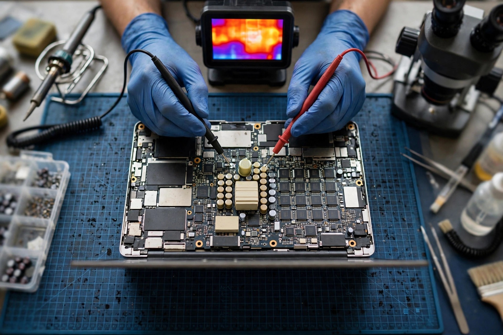
1. Scope: this article covers the ADVANCED mainboard short-circuit layer only
This article applies to one narrow situation, and only when a strict precondition is already met: the adapter, cable, charging port, USB-C PD negotiation, charger IC, EC, and power sequencing have all been excluded, yet the machine still shows one of the following: it trips the moment power is connected, the adapter light flashes, one area of the board feels hot, a fuse has blown, or the machine will not start. In other words, the starting point here is not a machine that will not turn on, but a machine where power has already reached the board in the correct form, the earlier layers have been shown not to be the break point, and yet some board power rail presents an abnormally low resistance path to ground, or protection triggers the moment power is applied. If the reader has not excluded the adapter, port, PD negotiation, charger IC, EC, and sequencing, this article is not the right one; those layers should be revisited first, and their content must not be rewritten here, nor should this article be used as a general guide to every machine that will not start.
Three layers must be separated at the outset, because they can look identical from the outside and they are the backbone of everything that follows. An input-layer problem means power never reached the board in the correct form. A sequencing-layer problem means power arrived and the EC is working, but some rail, signal, or power-good aggregation point sticks, and the chain never reaches CPU reset release. A short-circuit-layer problem means some power rail has developed an abnormally low resistance path to ground, current is drawn away through that path, protection triggers, a fuse melts, or one area heats abnormally, and the chain may stop at the power layer before it ever reaches the sequencing stage. All three can present as not starting, flashing once, or cutting out immediately, and no lamp or fan behaviour alone can separate them. That point must be stated at the beginning, so that no reader mistakes watching a light for a diagnosis, or mistakes swapping an adapter for completing a diagnosis. The first step of short-circuit diagnosis is not replacing a part; it is establishing which rail is shorted, and only then discussing which class of part and which section of the circuit is involved.
| Neighbouring layer | What it covers | What this article does not cover |
|---|---|---|
| Adapter and charging port layer | The adapter output itself, the cable, and socket contact | No adapter buying guide, cable specification, or socket replacement detail in this article |
| USB-C PD negotiation layer (batch77) | PD handshaking, voltage-step negotiation, and CC-line communication | No PD step table and no negotiation-failure mechanism rewritten here; only one boundary sentence is used when a trip must be distinguished, namely that a PD negotiation failure and a board short can look alike, and the break point must be separated by a bench |
| Charger IC layer (batch78) | The charger IC itself, charging current, and the charging path | No charger IC model numbers and no charging curves; a MOSFET or capacitor short near the charger IC is mentioned only from the short-location angle, never rewritten as a charger IC article |
| EC layer (batch74) | A dead EC, no response, or a stuck firmware state | EC failure is not used here as a universal answer |
| Power sequencing layer (batch79) | PWRBTN#, SLP release order, PWRGD aggregation, and PLTRST# | No sequencing chain rewritten here; a mid-sequence cut-out and a protection trip caused by a short can look the same, and separation requires bench measurement, never a count of flashes |
2. Stop rules: what to do first, and what never to do, when a short is suspected
When a board short is suspected, the first action is not another trial; it is to stop. Do not repeatedly plug in the adapter to see whether the machine will come on, because an original adapter under a short will repeatedly deliver large current or trigger its protection, and that can burn through inner-layer copper, turning a fault that could be located into a compound fault that is far harder to repair. Every repeated power-up gives the short path another chance to spread heat and current to neighbouring parts; try often enough, and a single clear break point can become several blurred damage sites, while the bench then needs far more isolation work to recover the picture. Stopping is itself protection of evidence: what the symptom looked like the first time, whether the trip happened on plug-in or only after the power button, how the adapter light behaved, and which area felt hot are first-hand records that repeated trials will wash away and can never be reconstructed afterwards.
The second stop rule concerns measurement itself. Before any resistance measurement, the adapter and the internal battery must be disconnected, and the board must be unpowered before resistance or diode-range readings are taken; a resistance or continuity reading taken on a powered board is invalid, and it can actively mislead judgement. This is not a bench habit but a limitation of the instrument: a resistance range infers resistance from the test current of the meter itself, and if board current is still present, the two currents mix and the reading no longer reflects the true state of that rail to ground. What the reader needs to retain is not how to disconnect a battery connector, but a judgement: any instruction that tells you to measure resistance while the machine is still plugged in should not be followed, and every step that tells a reader to open the bottom cover, disconnect a battery connector, remove the board, lift a shield, solder, fly a wire, inject voltage, or replace a MOSFET, capacitor, or fuse is outside the reader's scope. This article teaches none of those steps, and readers should not attempt them.
The third stop rule concerns fuses and protection parts as trial tools. After a fuse has blown, it must not be bridged, must not be replaced with a higher-rated part, and must not be replaced and immediately powered up to see whether it blows again; all of those practices defeat the protection. Bridging a fuse removes the protection entirely, so the next overcurrent has nothing to stop it, and what burns next is a downstream part, a trace, or the board itself. Fitting a higher-rated part raises the protection threshold artificially, so the extra current and heat in between are absorbed by the downstream circuit before anything cuts out. The only useful reader action is to record: who reported the blown fuse, whether that report came from a bench inspection or from a guess, what the machine did before the fuse blew, and whether a replacement blew immediately. That record, handed to the bench, is far more useful than a self-fitted fuse trial.
The fourth stop rule puts data before further trials. When a short is suspected, the first priority is to stop repeated power-ups, so that the short does not spread to the storage-device supply rail or expose a still-readable storage device to abnormal supply conditions. Before board repair, the data path should be assessed: which files cannot be lost, whether the storage device is removable, whether a backup exists, and whether encryption is involved. Getting that order wrong, repairing the board first and thinking about data afterwards, is a common error this article corrects; data and machine must be considered separately, because a repaired machine does not automatically mean the data is safe, and an unrepaired machine does not mean the data is lost. Before inspection, the reader should privately note which data needs decryption authorisation and which does not, but passwords must never be written on a sticker on the machine or attached casually with it.
3. Terminology first: rail, resistance to ground, diode-range reading, hard, soft, and intermittent shorts
If the terminology is unclear, every later distinction will blur. The first word is rail, meaning one supply network, for example a main rail, a standby rail, a CPU core rail, a GPU core rail, a PCH rail, or a memory rail. On one board, the normal resistance to ground of different rails can differ by several orders of magnitude, and no single number can judge all rails; that is the single most important judgement principle in this article. Naming follows the schematic of that model: Windows laptop schematics commonly use VIN, ADP+, B+, and VALW for the input and main-rail region, while older Intel Apple machines commonly use PPBUS_G3H for the main system bus, and the two naming systems must never be swapped. PPBUS_G3H must not be written as a universal rail name for all laptops, and VIN must not be written as an Apple rail name. Readers do not need to memorise which model uses which name; they only need to understand that a rail name means something only when the model and the board schematic behind it are stated.
The second pair of terms is resistance to ground and diode-range reading, and the two must never be confused. Resistance to ground means the resistance of a rail to ground, GND, measured with a meter after power has been disconnected, with the battery and adapter removed; a diode-range reading means the forward voltage-drop reading in diode mode, and its unit is not the ohm, so the two measure physically different quantities. Writing a diode-range number directly as an ohm value, or treating an ohm value as a voltage-drop reading, is simply wrong. Two further basic interferences must be known: the meter leads themselves have resistance, so low-resistance measurement must first be zeroed to cancel lead resistance, or lead resistance can swamp the genuine low-resistance difference; and large capacitors on the board are charged by the meter's own test current, so a reading can climb slowly from low, or beep briefly at the start and then recover, and that is not a short disappearing but the normal behaviour of a charging capacitor. No conclusion should be drawn from a single jumping reading.
The third group is hard, soft, and intermittent shorts, and the three need different handling, so they must not all be written as short. A hard short, also called a dead short, is a path of near-zero resistance, low in both measurement directions, and not climbing with time. A soft short, also called leakage, is a path whose resistance is low but not zero, or which changes with temperature or voltage. An intermittent short is a path that comes and goes, changing when the board is lightly pressed, lightly flexed, or heated and cooled. Hard shorts point toward a fused device, a dead-shorted capacitor, a solder bridge, or a failed protection part; soft shorts point toward cracked-capacitor leakage, tantalum leakage, corrosion leakage paths, or integrated-circuit leakage; intermittent shorts point toward the thin conductive path of a cracked capacitor, tin migration, a poorly contacted bridge, or a corrosion dendrite that has not fully connected. Separating the three makes an inspection description accurate; writing everything as short only forces the bench to separate them again from the beginning.
| Term | Meaning | One sentence for the reader |
|---|---|---|
| Rail | One supply network, for example a main, standby, or core rail | Different rails can have normal resistances differing by orders of magnitude, so no single number judges all rails |
| Resistance to ground | The resistance of a rail to ground after power is disconnected | It is only valid with the adapter and battery disconnected; measuring while powered is meaningless |
| Diode-range reading | The forward voltage-drop reading in diode mode | Its unit is not the ohm, and it must not be swapped with a resistance value |
| Hard short | A near-zero resistance path | Points toward a fused device, a dead-shorted capacitor, a bridge, or a failed protection part |
| Soft short | A low but non-zero resistance, or one that changes with temperature or voltage | Points toward cracked-capacitor leakage, corrosion leakage, or integrated-circuit leakage |
| Intermittent short | A path that comes and goes | Points toward a thin cracked path, tin migration, or a dendrite that has not fully bridged |
4. A map of board power rails: recognise the rail before discussing the short
The first step of short-circuit diagnosis is not replacing a part; it is recognising which rail is shorted. On one board, a short on a main rail, a standby rail, or a CPU core rail means something entirely different, with entirely different danger; recognising the wrong rail makes every later inference wrong. From high voltage to low voltage, the typical hierarchy is only a logical hierarchy, not a specification table for any one board: the input and main-rail region passes through input protection, a fuse, and current sensing to become the main system bus; the standby and always-on region stays powered even when the machine is off, supplying the EC and standby logic; the system-rail region is built up step by step after power-on, including PCH rails, memory rails, CPU core rails, GPU core rails, and display and peripheral rails. Each step-down stage is generally a synchronous buck switching supply, built from a high-side MOSFET, a low-side MOSFET, an inductor, and output capacitors, and repair literature notes that measuring across a large inductor is a common starting point for recognising a rail, because the inductor is the output filter point of that rail. On protection, a buck controller generally provides current limiting, thermal shutdown, and undervoltage lockout; on an output short, current limiting makes the controller stop driving the power devices, or fold back its output, so that current is not amplified without limit. This article states only the concept that protection exists and will trigger a shutdown; it never writes the protection parameters of one particular part as if they were the parameters of the reader's machine.
The practical meaning of recognising rails can be shown with three contrasts. First, a main-rail short and a standby-rail short do not behave the same: a main-rail short triggers protection the moment power is connected and the whole board may show nothing, while a standby-rail short can leak or heat continuously even when the machine is off, because the standby rail is powered in the off state, so standby power never establishes itself and the sequencing chain stops before it starts. Second, a system-rail short is narrower in scope: one system rail shorted pulls down only that group, while other rails may stay normal, and that is the value of recognising rails one by one, because measuring the inductor output of that group shows low resistance while other rails stay normal, and the short narrows to that group. Third, a core-rail short has the highest judgement threshold: a core rail's normal resistance is itself extremely low, so measurement error, lead resistance, and model-to-model variation can all produce false alarms, and only a same-model comparison carries meaning. Recognising a rail is not memorising a universal specification table; it is stating, for that model's schematic, the voltage layer, the supplied loads, the normal resistance tendency, and the behaviour when shorted, rail by rail.
| Board location and measurement point | Concept | Note |
|---|---|---|
| Near the DC input: large capacitors, fuse, and input MOSFET region | Input and main-rail region; on older Apple machines, the PPBUS_G3H region | Highest voltage and most upstream; protection triggers first when shorted |
| Standby and system inductor outputs | Standby and system rails | Always-on rails that stay powered when off; a short can leave the whole board without standby power |
| Inductor group near the CPU, multiphase buck | CPU core rail | Low voltage and high current; normal resistance to ground is itself extremely low |
| Buck inductor group near the GPU | GPU core rail | As above; normal resistance is also extremely low |
| Inductors near the PCH and memory | PCH rail and memory rail | Low-voltage rails; a short must not be judged by main-rail standards, just as with core rails |
5. The 19V VIN rail and the main rail: why its short is the most conspicuous
The main rail is one of the highest-voltage and most upstream rails on the board, so when it shorts, the adapter or PD supply faces a near-zero load the moment it is connected, protection triggers immediately, and the result is a flashing adapter light, an immediate cut-out, or a melted fuse. That mechanism looks extremely similar to a faulty adapter, and separation requires powered-off measurement of the main rail to ground, not an adapter swap. Repair writing notes that the main-rail region, including the input, main-rail, and standby-system region, is a common inspection area for main-rail shorts, and that common suspects for a main-rail short include filter capacitors and MOSFETs near the input. A switching supply provides current sensing, so an output-side short drives current sharply upward, the controller stops driving the power devices, and the whole supply shuts down within an extremely short time; an inexperienced observer can easily misread that as a faulty power supply. This article retains that warning: power cutting out the moment it is connected does not mean the adapter is faulty, and it does not mean the board is certainly shorted; both possibilities need powered-off measurement before they can be separated.
The danger of a main-rail short is not only that the machine will not start, but also where the rail sits. The main rail is the most upstream, and it feeds every supply group on the board, so a short on it affects the whole board supply; its protection trip can also mask downstream problems, because power never reaches the later stages at all. When a bench handles a main-rail short, its thinking runs section by section: before or after the fuse, in the input protection section or in the later stages, in the charging path or in a system-rail branch, disconnecting one section and measuring again each time. What the reader needs to understand is not the isolation steps themselves, but why a main-rail short cannot be solved by swapping adapters: swapping the adapter only changes the power source, while the short path stays on the board, so a new adapter faces the same low-resistance load and triggers the same protection; repeated adapter trials only make protection cycle repeatedly, and never make the short path disappear.
One further detail is worth stating: a main-rail short and a standby-rail short can differ in their heating behaviour over time. A main-rail short mostly triggers protection the moment power is connected, so heat may have no time to accumulate; a standby-rail short, because the standby rail stays powered while the machine is off, can leak and heat continuously, so one board area may stay slightly warm even though the machine was never switched on. The two heating time patterns differ, and an inspection description should state whether heating appeared immediately on plug-in, only after power had been connected for a while, or whether an area felt as if it had been warm even without power. The time pattern alone is not a diagnosis, but it is an important clue for the bench in narrowing down the rail, and a reader recording it should always write it together with the power state, never as a bare statement that one area feels hot.
6. PPBUS_G3H: old Intel Macs only, never generalised
PPBUS_G3H is the main system bus concept on older Intel Apple mainboards, generated around the charger IC, adjusted by system management to a stable value, and then distributed to the various supply rails. This concept applies only to older Intel Macs, and it must never be generalised: PPBUS_G3H must not be written as a universal rail name for all laptops, VIN must not be written as an Apple rail name, and PPBUS and SMC concepts must never be forced onto Apple Silicon machines. Apple Silicon machines have no independently user-resettable SMC, and their power architecture differs from Intel machines; this article provides no Apple Silicon power architecture detail, and any Apple Silicon short suspicion must be left to inspection against that model's own information. PPBUS voltage itself depends on the battery configuration of the model, and different models have different values, so this article writes no single unified PPBUS standard voltage, and any statement that presents PPBUS as a fixed voltage is wrong.
An individual repair case shows an isolation way of thinking that is worth referencing, provided it is stated as an individual case and not as a universal procedure. In one older Intel Mac case, after the main system bus was measured as shorted to ground, the fuse was first opened to separate the sections before and after the fuse; once the short was confirmed to lie in the later section, the main-bus connection points were opened one by one against the board diagram, and after one filter capacitor was removed, the ground reading returned to normal. The value of that case is not the fuse number or the capacitor number themselves, but the isolation logic: first split the circuit into before and after sections, then narrow section by section, and finally verify with the resistance change before and after removal. Readers should not memorise the numbers from that case and apply them to their own machines, because numbers, positions, and parts differ completely across models and board revisions; what readers should retain is how a bench thinks, namely that a whole rail measuring shorted only proves that a short path exists somewhere on that rail, not that the part near the measurement point is shorted, and only isolation can narrow it to one section.
There is one more warning for this section: a main-bus short on an older Intel Mac and a main-rail short on a Windows laptop share a mechanism concept, but their rail names, voltage layers, distribution structures, and system-management roles must never be swapped directly. Whenever PPBUS is mentioned in writing, the old-Intel-Mac qualifier must be mentioned at the same time, and the qualifier must not be dropped in headings, tables, or conclusions in a way that lets a reader believe every machine has PPBUS. The qualifier is not clutter; it is a necessary part of preventing misdiagnosis. Dropping it turns a model-specific concept into a supposed universal truth, after which a reader understands their own machine against the wrong rail, and the whole value of the distinction collapses.
7. Shorted ceramic capacitors (MLCC): the most common source, and the easiest to misjudge
MLCC stands for multilayer ceramic capacitor, built from ceramic dielectric and interleaved electrode layers, and ceramic is brittle. Failure-analysis literature states that one common cause of low insulation resistance and shorting in MLCCs is cracking, especially flex cracking: bending of the board, assembly, and handling stress can crack a rigid MLCC, with the crack extending inward from the termination edge and exposing the surfaces of two or more opposing electrodes; moisture or conductive matter entering the crack can then, under bias, undergo migration and form a low-insulation-resistance or short path, and heat generated by the failure can widen the crack further and worsen the condition. The same literature notes that MLCC designs with flexible terminations aim to let the termination tear before the ceramic body, so that failure tends toward an open circuit, the safer direction, rather than a short, and that improved designs can tolerate greater bending. This article can state that flexible termination is a mitigation design against crack shorting, but it must not be written as if a flexible termination meant a part could never short; mitigation is not immunity.
Another MLCC survey states that the most common description of an MLCC short is a short in a low-voltage, high-impedance circuit, with the mechanism being ceramic micro-cracking plus moisture plus ionic migration under polarising voltage, forming an extremely thin conductive path; that path is so thin that voltage beyond a certain level may burn it open, while excessive voltage may also flash over at the crack, and neither outcome is good. Forum engineering discussion adds an important detail: a crack need not cause a dead short immediately, because the crack first lets moisture in, leakage current rises slowly, and failure can worsen long after the original bending event; some repair observers have also noted that a cracked capacitor's cold resistance can be at a leakage level rather than zero. When that point is cited, it must be labelled as forum observation, and its purpose is to warn readers that a reading need not be zero to be a matter for suspicion, since abnormal leakage is also a direction for suspicion.
Which MLCCs are most worth suspecting should be argued by position logic, not by hit-rate statistics. Input and main-rail filter capacitors sit directly across a high-voltage rail and ground, so a short there pulls down the whole main rail at once; the filter capacitor at each buck output sits across that rail and ground, so a short there pulls down only that group, and measuring that group's inductor output shows low resistance while other rails may stay normal, which is precisely the value of recognising rails one by one; capacitors at board edges, near connectors, near screw holes, and in frequently stressed positions sit where bending stress is greater, and the crack-risk concept comes from failure-analysis literature, but which position cracks most easily varies with board design, so this article never writes a universal ranking for the whole board. The appearance trap must also be stated: a shorted MLCC need not show burn marks, and a shorted MLCC can look intact with no visible damage, because the conductive path lies inside the ceramic body. Looking unburnt does not mean there is no short, and looking burnt does not mean that part is the short path; both sentences must be stated together.
8. Tantalum capacitors: another kind of capacitor that tends toward shorting when it fails
The failure mode of tantalum capacitors tends toward shorting, unlike the crack mechanism of MLCCs. Repair discussion notes that a shorted tantalum capacitor can be accompanied by smoke, sparks, and a blackened case, and also notes that tantalum capacitors should be used with voltage derating to be reliable, and that surge current should also be limited, because insulation damage can otherwise lead to large leakage and even catastrophic failure. This article states only the direction that tantalum failure tends toward shorting, and writes no specific derating percentage as a universal specification, because derating advice differs across makers and series, and no universal maker figure has been verified. The conceptual distinction is this: MLCC shorts are mostly connected with mechanical cracking and moisture, while tantalum shorts are mostly connected with overvoltage, surge, and insulation degradation. The two kinds differ in board shape, position, and marking, and a bench distinguishes them from the schematic and part number; readers neither need to nor should attempt to distinguish them by removing parts themselves.
The tantalum section also carries an inspection meaning: a tantalum short sometimes leaves clearer external traces, such as blackening, deformation, or smell, and those traces are worth photographing, with the time and power state recorded, but they must not be treated directly as a diagnosis. An external trace can be caused by the short itself, or it can be a secondary trace left when other parts heated after the short; which is the origin and which is the result can only be separated by isolation. When a reader records appearance, the position and extent of the trace should be written, together with whether it appeared on the first power-up or only after repeated trials; a trace that appeared only after repeated trials may itself be spread caused by the trials, and stating the number of trials helps the bench judge origin versus spread.
9. MOSFET drain-source breakdown: how one device can drive high voltage into a low-voltage rail
A power MOSFET has three terminals, gate, drain, and source. Normally the gate controls switching of the drain-source channel; on failure, the drain-source path can become a permanent low-resistance path, which is a drain-source short. A failure-mechanism guide states that one typical failure of power MOSFETs is a permanent low-resistance short between all terminals, usually arising from thermal failure during operation: a hot spot on the die rises until the junction becomes intrinsic, extreme current density fuses that region's structure, including silicon and oxide, forming a vertical fused filament from source metal straight through to drain metal, and the measured short resistance can range from extremely low to several tens of ohms. Such damage is generally marked as electrical overstress or electrically induced physical damage, and physical analysis alone cannot work backwards to the specific working mode and conditions at the time. The same guide notes that a drain-source open circuit is extremely rare, and that a more common open circuit is a gate or source bonding problem; in other words, when a power MOSFET fails, it mostly tends toward shorting rather than opening. Another failure survey notes that gate-oxide breakdown creates a conductive path between gate and drain or source, raises leakage current, and removes control ability, with overvoltage, overcurrent, overheating, and static discharge as common inducements. When cited, the two must be kept apart: gate breakdown and drain-source fusing are two different failure paths, and they must not be conflated.
A high-side short and a low-side short have entirely different consequences, and this is the most important distinction in this article. In a buck stage the high-side device connects to the high-voltage input, the low-side device connects to ground, and the output is taken between them through an inductor. A low-side drain-source short pulls the output rail toward ground, so that rail measures low to ground, but high voltage is not driven directly into the low-voltage rail; repair discussion notes that with a low-side short, the measured result is a core rail low to ground, and the core itself may not yet be damaged, although damage cannot be ruled out. A high-side drain-source short drives the high-voltage input directly through the shorted device into the low-voltage output rail, so low-voltage parts on that rail face voltage far above their ratings, and the risk of damage rises sharply. Repair writing warns explicitly that power must never be applied directly before rail impedance has been verified, because a high-side short drives the whole high-voltage rail straight into the CPU core. Other discussion notes that with a high-side short, the measurement shows low resistance between the high-voltage main rail and the core rail, and the main rail to ground is also low, and that newer, more sensitive CPUs are more easily damaged. The correct writing stance is this: a high-side short may damage low-voltage parts, it does not certainly kill them; a low-side short may leave them undamaged, it does not certainly leave them safe.
MOSFET short inducements should be discussed at the mechanism level, never written as the cause of an individual case. Electrical overstress covers overvoltage, overcurrent, and surge, fusing a die hot spot; gate overvoltage breaks down gate oxide; thermal stress covers prolonged high temperature and poor heat removal, degrading substrate and oxide. There is also a special case worth stating: a failure analysis records an intermittent drain-source short in which the device measured normal after removal, and a large current on re-powering made the short disappear again; high-magnification inspection found a dendritic tin-migration structure between the drain and source pads, proving that the short path lay not inside the die but on the package surface and between pads, and that the path had limited current-carrying ability, so a large current could burn it open. The value of that case is a warning: a drain-source measurement showing a short does not mean the die itself is certainly faulty, and an intermittent short that disappears after a large current has not been repaired, because the migration path can regrow. The bench logic for suspecting a MOSFET is powered-off measurement of drain-source and gate-source around the input MOSFET and the buck high-side and low-side devices, read against the schematic to establish which device sits across which rail; only when a suspect device is removed from the board, the board rail resistance recovers, and the removed device still measures shorted on its own, can that device be called shorted. If the removed device measures normal, the short path may lie elsewhere on the board, around the pads, traces, or a migration path, and no conclusion should be rushed.
10. Other short sources: not every short is a capacitor or a MOSFET
Protection parts themselves failing are a first easily missed source. TVS and Zener protection parts can become shorted after absorbing overvoltage, playing the role of sacrificing themselves and pulling the rail voltage down; before replacing one, the source of the overvoltage must first be found, or a new part can fail immediately. That point belongs to general protection-circuit concepts, and no universal maker figures have been found, so this article states only the concept and never writes any specific model or parameter. A second source is connectors, flex cables, and solder bridges: foreign matter, bent pins, or solder bridging near a USB port, charging port, or display cable connector can connect a power rail directly to ground; the external inducements for that kind include water entry, impact, and insertion damage, and they must be separated by visual inspection and history, never blamed uniformly on ageing parts.
A third source is inner-layer and trace damage: an inner-layer short in a multilayer board, or traces that have burnt open and then touched together, cannot be seen from the surface, and thermal imaging and injection may both fail to locate them; the repair difficulty and board-replacement consideration for that kind must be handled separately inside the decision framework. A fourth source is an integrated-circuit body short: a power-management IC, a charger IC, a southbridge or PCH, or a CPU or GPU body can short internally; a body short and a short in that IC's surrounding capacitors can measure identically on the board, so separation requires isolation, and no measurement number alone should name one particular IC. A fifth source is corrosion and migration shorts: they require moisture plus ionic residue plus bias all together, and not every damp machine should be written as a corrosion short. Writing every short as a capacitor or a MOSFET is the most common simplification error; the fuller the short-source list, the clearer it becomes why a bench must isolate section by section instead of replacing a part directly from a symptom.
11. Cold-measurement logic: resistance to ground, diode range, and the false-short trap
Need a laptop repair expert?
Free diagnosis · Transparent pricing · No fix, no fee · 180-day warranty
The measurement preconditions were stated in section 2, and this section discusses the measurement logic itself. First, before any resistance-to-ground measurement, the adapter and the internal battery must be disconnected, and the board must be unpowered before resistance or diode-range readings are taken; fuse-diagnosis writing states explicitly that resistance or continuity ranges must not be used on a powered board, and that resistance readings are only valid on an unpowered circuit. Second, the meter leads themselves have resistance, so low-resistance measurement must first be zeroed to cancel lead resistance, or lead resistance can swamp the genuine low-resistance difference. Third, the capacitor-charging effect makes readings climb slowly from low, or beep briefly at the start and then recover, and that is not a short disappearing but the normal behaviour of a charging capacitor; no conclusion should be drawn from one jumping reading. Fourth, the meter's own test conditions affect readings: the test voltage of a resistance range differs across meters and can be enough to turn a semiconductor junction on, so the same node can read differently on different meters and different ranges; a different reading on another meter does not necessarily mean the board condition has changed, because the meter test conditions may differ.
The false-short trap is the core of this section. The core principle is that every rail has its own normal resistance to ground, and the judgement standard is the resistance that rail itself should have, never a universal threshold stated as below some value means short. The reference ranges offered by repair literature belong to the repair-literature level, not to maker specifications, and that qualifier must be added; this article never writes those reference ranges as a standard table for all machines, and it uses only their comparison logic to explain the trap: a low reading measured on a CPU core rail can be entirely normal, while the same reading on a main rail or a peripheral rail would be a catastrophic dead short. The mechanism explanation is that CPU and GPU core supplies are low-voltage, high-current designs, with cores built from large parallel circuits, so their equivalent resistance to ground is itself low, and with multiphase buck stages in parallel and many decoupling capacitors in parallel, the cold equivalent resistance is naturally at an extremely low level. That is a design characteristic, not a fault; without stating that mechanism, readers will treat every low reading as a short.
On judgement method, bench logic combines three things: a known-good board of the same model for comparison, reference values in that model's schematic or service manual, and comparison across several measurement points on the same rail, and a conclusion should not be drawn if any of the three is missing. There is no official resistance-to-ground table from any maker for any model, and repair-literature references must never be written as a standard for all machines. The role and limits of diode mode must also be stated: diode mode measures the forward voltage drop of a semiconductor junction, not resistance; repair literature notes that one side of a normal capacitor shows a charging curve or an open reading, and only when both sides show a near-zero reading is a short suspected, with a normal diode-range reading lying in a higher range and an extremely low reading indicating that the rail may be shorted. But a core rail's normal diode-range reading is itself extremely low, so diode mode has almost no discriminating power on a core rail, and a near-zero diode reading must never be written as evidence of a core-rail short. On two-direction measurement, repair literature notes that a normal board should not show similar low readings in both directions, and only similar low readings in both directions point toward a short; that is an empirical rule from repair literature, and it must be labelled at that level, never written as a maker standard.
| Form | Measurement character, described conceptually | Direction for suspicion |
|---|---|---|
| Dead short, hard short | Near zero, low in both measurement directions, not climbing with time | A fused part, a dead-shorted capacitor, a solder bridge, or a failed protection part |
| Soft short, leakage | Resistance low but not zero, or changing with temperature or voltage | Cracked-capacitor leakage, tantalum leakage, corrosion leakage paths, or integrated-circuit leakage |
| Intermittent short | Comes and goes; the reading changes on light pressure, light board flex, or heating and cooling | The thin path of a cracked capacitor, tin migration, a poorly contacted bridge, or a corrosion dendrite not yet fully connected |
12. Location methods: injection, thermal imaging, rosin, and alcohol, their principles, limits, and dangers
The methods below all belong to bench operation. This article states only how a bench thinks and why it thinks that way; it never writes them as reader instructions. The principle of injection is Joule heating: a short path, although low in resistance, is not zero, so current passing through it generates heat according to Joule's law, and the place where heat concentrates most is the short path itself, or the part closest to it. The operating principles are stated as three sentences only: apply a low-voltage, current-limited supply to a rail already confirmed as shorted; the voltage must stay below that rail's rated value, and high-rail voltage must never be driven into a low-voltage rail; and the current must start low and be observed step by step, never opened large at the start. Different repair sources give inconsistent current-limit figures, so this article copies no set of figures as a universal standard and states only the three principles of low voltage, current limiting, and never exceeding that rail's rated value; the specific figures are for that model, that rail, and that bench to judge, and choosing one appealing figure to write into an article would itself be an error.
The blind spot of injection must be stated, or readers will treat injection as infallible. When a current-limited supply meets an extremely low-resistance dead short, it enters current-limiting mode, its output voltage falls to near zero, the power actually delivered to the board can be extremely small, and even the leads may feel only slightly warm, so the shorted part may never heat at all; for a part to heat, the short path needs a certain resistance, or current would have to be driven without limit, and the latter is precisely the dangerous practice. The inference is that no heating under injection does not mean no short; the cause may be a short path of too low resistance, a limit set too conservatively, or heat carried away by a large copper area. A bench then changes to milliohm-gradient measurement or to piece-by-piece isolation, rather than simply raising the current. The milliohm-gradient concept is that copper traces themselves have milliohm-level resistance, so measuring along a power copper area from far to near shows lower and lower resistance as the short point is approached, and the physical node with the lowest resistance lies near the short point; that is a concept, and writing here never turns example figures into a standard.
Thermal imaging, rosin, and alcohol are three ways of seeing heat, each with its own uses and limits. Thermal imaging detects infrared radiation and turns it into a temperature distribution map, with the short point hotter than neighbouring parts; its advantages are speed, non-contact operation, and seeing a whole board at once, while its limits are that close-up and high resolution are needed to separate small parts, an extremely low-resistance dead short may not heat enough, and normal high-current parts are themselves hot, so hot does not mean faulty. The rosin method lays a thin layer of rosin on the board surface, and heat at the short point melts the rosin, producing smoke or bubbling; its advantages are low cost and direct visibility, effective for small-area location, while its limits are that cleaning is needed afterwards, and rosin quantity and heating time must be controlled, or they can hide or mislead, and the method only suits shorts that actually heat. The alcohol method lays a thin layer of isopropyl alcohol on the board surface, and the short point heats first, so its alcohol evaporates first, and the place that dries fastest is the hot spot; its advantages are low cost, speed, and no residue, while its limits are that alcohol is flammable and must be handled by a bench under ventilation, with no open flame, and after power-off cooling, and that slight heating may not show a visible evaporation difference. Forum opinion is divided: some repairers find the alcohol method more direct than thermal imaging in some cases, while others note that it is insensitive when heating is slight, and both views must be retained, never written as if alcohol were certainly better than thermal imaging. The common trap is that a hot spot does not equal a short point, because heat travels along copper, and a genuinely shorted small capacitor may stay cool while a nearby large copper area, inductor, or integrated circuit feels hot through conduction; location must combine rail, position, and isolation results, and no single thermal image should name a faulty part.
The safety boundaries of injection, stated conceptually, are only three sentences: high-rail voltage must never be driven into a low-voltage rail, because driving main-rail voltage into a standby, system, or core rail makes low-voltage parts face voltage far above their ratings and damages them; injection must never be applied blindly before the shorted rail has been confirmed, because injecting into the wrong rail means actively driving power into a healthy rail, which can itself create a new fault; and the battery must first be disconnected, because an injection supply in parallel with a battery makes the current path uncontrolled and creates a safety risk. Writing here states only that a bench first confirms the rail, disconnects the battery, and sets limits from that rail's rated value; it never writes a step-by-step procedure. Why forcing a short open with a large current is a dangerous idea must also be stated: a short path burnt open by a large current does not mean a repair, because what burnt open may be a trace, a pad, or a copper area rather than the faulty part itself; once a trace has burnt open, the board may develop a new open-circuit fault and become harder to repair; a large current can widen the fault, so a case that began as one shorted capacitor can heat-damage neighbouring integrated circuits, MOSFETs, and traces together; and an intermittent short that disappears after a large current has not had its root removed, because a migration path can regrow.
13. Isolation rail by rail: how a whole-rail short narrows to one part
The logic of isolation follows from the fact that a power rail is a parallel network. Dozens of capacitors, several integrated circuits, and several MOSFET groups all sit in parallel between the same rail and ground, so measuring a rail as shorted to ground only proves that a short path exists somewhere on that rail; it does not prove that the part near the measurement point is shorted. Discussion states this point explicitly: every capacitor on the same supply line will measure shorted, because the short path lies on the same line. Isolation therefore means disconnecting parallel branches one section at a time and measuring again after each disconnection: when resistance recovers after one section is disconnected, the short path lies inside the section just disconnected; when the rail stays shorted, the short path lies in a section not yet disconnected. Isolation is not doing more by removing more; every disconnection must carry a hypothesis to be tested, stating which section is suspected before disconnection, and stating how the result changes the judgement afterwards, or removing dozens of parts is only damage, not diagnosis.
Common isolation break points should be described as bench logic, never as reader steps. On the fuse break point, the older Intel Mac case first opened the fuse to separate before and after sections; a fuse itself is not an isolation tool but a protection part, and opening it for measurement is only a bench diagnostic method, after which the correct part must be fitted again to specification, and it must never be bridged long-term. On the inductor and bead break point, a buck output inductor connects the power stage at one end and the load rail at the other, so opening the inductor separates a short in the power stage from a short on the load side; repair discussion notes that an inductor's own resistance is extremely low, so measuring an inductor as conducting does not judge whether a power device is good or bad, and it must be read together with rail segmentation. On zero-ohm resistor and jumper break points, some boards use zero-ohm resistors as rail segments, and opening one disconnects that branch. On removing capacitors one by one, when no break point is available, a bench follows the board diagram and removes the capacitors on that rail one at a time, measuring after each removal; the part whose removal restores resistance is the suspect; but thermal location must narrow the range first, or removing dozens of capacitors one by one wastes time and adds pad-damage risk. On integrated-circuit break points, when an integrated-circuit body is suspected, a bench can open the IC supply pins or remove the IC and measure again; but removing a ball-grid-array CPU, PCH, or GPU carries extremely high risk, and it is not a routine isolation method, so the decision must be handled inside the decision framework.
| Isolation result | Reading |
|---|---|
| After one section is disconnected, rail resistance returns to normal | The short path lies inside the section just disconnected; narrow further inside that section |
| After every peripheral section is disconnected, the rail is still shorted | The short path may lie in the main trunk, in an inner layer, or in a core integrated-circuit body not yet disconnected; board replacement consideration rises |
| After a suspect part is removed, the rail recovers, but the removed part measures normal on its own | The short path may lie not in that part itself but in its surrounding pads, traces, or a migration path; do not rush to refit the same part and close the case |
| After a suspect part is removed, the rail is still shorted | That part is not the short path, or it is not the only short path; continue isolation, and do not write that part off as excluded and then forget to refit or handle it |
14. Reading fuses, TVS parts, and eFuses: what a blow means, and why a new fuse blows again
The role of a fuse is to melt open and cut the circuit when current exceeds its design value, protecting what lies downstream. Fuse-diagnosis writing states explicitly that a blown fuse only proves the circuit was once interrupted, never why the overcurrent happened; before any fuse is replaced, the protected rail must be checked for a short; a fuse must never be bridged, and must never be replaced with a higher-rated part, or a repair can become a fire or a dead-board risk. On diagnostic logic, measuring both ends of a fuse while powered off shows conduction when the fuse itself still conducts, and an open reading consistent with a blow; but measuring across a fuse cannot prove that the rest of the circuit is healthy, because parallel paths can affect the reading, and one end may need to be isolated before measuring again. On fuse types, some boards use one-time chip fuses and some use self-resetting fuses, and the two differ in characteristics, ratings, and packages, so they must be matched from that model's schematic; similar appearance does not mean interchangeability. This is a general concept, and no universal cross-reference table has been verified, so this article states only the principle of matching from the schematic.
The role of a TVS is entirely different from a fuse. A TVS normally presents high resistance, and on a transient overvoltage it clamps by conducting and diverting the surge energy away; after overstress, its typical failure mode is a short, and that direction is regarded in protection applications as an expected and preferable failure direction, because it turns the fault into a measurable short rather than letting overvoltage reach the later stages directly. But the other side must be stated at the same time: if a shorted TVS is not replaced, and a fuse is simply replaced and power applied again, the short is still present, and the fuse will blow again. The role of an eFuse is different again: an eFuse is an active protection system, containing a switching element, sensing, and control circuitry, able to limit current, clamp or cut off overvoltage, and shut down on overheating, with some types able to reset or requiring a fresh power-up to recover; datasheets state its design purpose as defending against overload, short circuits, voltage surges, and excessive inrush current. In other words, an eFuse is a protection system that acts, not a one-time melting wire; its reading cannot use a single continuity standard, and must look at its output rail, enable state, fault indication, and surrounding components.
The traps behind a fuse that blows again immediately can be organised as a checklist. First, the cause has not been removed, and the fuse is only the sacrifice: a public case shows exactly this pattern, in which a fuse behind the DC socket blew, a new one blew immediately on plugging in the adapter, and discussion pointed to another fault in the board circuit, not to the adapter's no-load voltage being normal as proof of health; a fuse is a warning, not an independent diagnosis, and replacing it before the cause is found can make it blow immediately again. Second, a TVS has already shorted but is mistaken for a downstream short, or the reverse: if the TVS itself has shorted, measuring the whole rail to ground will always show a short; if only the fuse is replaced without handling the TVS, the result is the same; if removing the TVS makes the short disappear, the fault narrows to the TVS itself and the overvoltage event it endured, but the source of that overvoltage event must still be accounted for, or a new TVS may sacrifice itself again. Third, a high-voltage rail has broken through into a low-voltage rail: measuring between the main rail and the inductor of the shorted rail shows near zero when the high-side MOSFET has broken down drain-to-source, giving high voltage a direct path into the low-voltage rail; when that measurement shows high resistance but the shorted rail to ground is zero, the high-side switch may be intact, and the fault lies in that shorted rail's own capacitors, low-side MOSFET, or load IC. That distinction decides whether replacing a fuse or a capacitor is enough, because with a high-side breakdown, replacing only later-stage parts will not solve the direct high-voltage drive. Fourth, the wrong specification has been fitted: a fuse's marking, rating, speed, package, and position in the circuit are all model-specific, and a substitute must not be chosen merely because it looks about the same size, must not use a larger rating, and must not be bridged; this article lists no universal fuse model cross-reference table, because the same position on different models and board revisions can be an entirely different specification, and the correct writing is to check the original specification from the board number and schematic.
| Part | What it does normally | Common state after fault or overstress | Meaning for reading |
|---|---|---|---|
| Fuse, often marked F on the board | In series with the power path; melts open when current exceeds its design value and cuts off later stages | Open circuit | Proves only that an overcurrent once occurred; does not prove the cause, and does not prove later stages are healthy |
| TVS diode, transient voltage suppression | Normally high resistance; on transient overvoltage it clamps by conducting and diverts surge energy away | Typical failure mode after overstress is a short | A shorted TVS itself creates a ground-short appearance; only after it is removed or isolated can the reading separate a sacrificed TVS from a genuine later-stage short |
| eFuse, an electronic fuse IC containing a MOSFET, sensing, and control | Uses its internal switch as a switch, actively limiting current, clamping or cutting off overvoltage, and shutting down on overheating; some types can reset or need a fresh power-up | After overcurrent or overvoltage it enters limiting, disconnection, or a latched state; not necessarily a burnt appearance | Cannot be judged by continuity alone; its output rail, enable state, fault indication, and surrounding parts must be read, and it must not be swapped as if it were an ordinary fuse |
15. Shorts on CPU, PCH, and GPU supply rails versus peripheral rails: a distinction framework
Why two classes of rails must be separated comes down to voltage layers and normal resistance tendencies. Core rails are low voltage, high current, and multiphase in parallel, with extremely low normal resistance, so the threshold for suspecting a short is extremely high, and measurement error, lead resistance, and model-to-model variation can all produce false alarms; peripheral rails are higher in voltage and lower in current, with higher normal resistance, so the same degree of low reading carries far greater meaning on a peripheral rail than on a core rail; main rails are highest in voltage and highest in normal resistance, so a low reading carries the greatest meaning there, and protection triggering is also most obvious. The distinction framework is not a standard table but a comparison logic: first state which class of rail, then that class's normal tendency, then what a low reading means on that class, then its common short paths, then its repair-difficulty tendency. Any statement that turns the framework into a cross-rail universal threshold is wrong.
| Rail class | Normal resistance tendency | Meaning of a low reading | Common short paths | Repair-difficulty tendency |
|---|---|---|---|---|
| Main rail | High, with repair-literature reference tending toward the high-resistance region | Extremely low resistance is a strong suspicion of a dead short | Input capacitors, input MOSFETs, protection parts, and charging-path parts | Relatively isolable: more break points and more peripheral parts |
| Peripheral rail | Medium to high | Low resistance points toward a short, but the normal low-resistance effect of parallel ICs must first be excluded | That rail's capacitors, connector protection parts, and peripheral ICs | Medium: section-by-section isolation is generally feasible |
| PCH and memory rail | Low to medium | Low resistance only carries meaning after same-model comparison | That rail's capacitors, the PCH body, and memory supply devices | Medium to high: board-replacement consideration rises when the PCH body is shorted |
| CPU and GPU core rail | Extremely low, at ohm level or below, on repair-literature reference | An ohm-level reading alone is not evidence of a short; only a reading far below the same-model normal range, or a high-side short feature, namely low resistance between the high-voltage main rail and the core rail, forms a strong suspicion | Core-rail capacitors, low-side MOSFETs, and core bodies, rarer but with the heaviest consequences | High: with a core-body short, or a high-side short that has already driven voltage into the core, board-replacement and machine-replacement considerations rise sharply |
On symptom comparison, every row must carry a qualifier: a symptom is only a direction for suspicion, never a diagnosis, and this article never writes that a given symptom means a given part has failed. A trip or flashing adapter light on plug-in points, on the short-circuit side, toward a main-rail short triggering supply protection and cutting output, or toward the adapter's own overcurrent protection acting; other possibilities include a faulty adapter itself, a charging-port short, a PD negotiation failure, and charger-IC protection. No start and no response at all points, on the short-circuit side, toward a main-rail or standby-rail short leaving standby power unestablished, so the sequencing chain stops before it starts; other possibilities include EC failure, a stuck sequencing chain, and battery or input-layer problems. A response on pressing the power button followed by an immediate cut-out points, on the short-circuit side, toward a system-rail short triggering protection and a sequencing withdrawal after power-on; other possibilities include a mid-sequence protection withdrawal, thermal protection, and supply-load problems. Heating in one board area points, on the short-circuit side, toward a standby-rail short path leaking and heating continuously, or toward a short point heating during injection location; other possibilities include normal high-current parts heating, poor heat removal, and other leakage paths. A blown fuse points, on the short-circuit side, toward an overcurrent on some rail melting the fuse for protection; other possibilities include the point that overcurrent does not necessarily mean a short, since surges, momentary connector overcurrent, and protection-part action are all possible, and the rail must be checked first rather than the fuse being replaced directly. Booting sometimes and not others points, on the short-circuit side, toward an intermittent short, with cracked leakage changing with temperature, humidity, and mechanical stress; other possibilities include poor contact, marginal sequencing, and intermittent battery or connector problems. One detail trap on adapter lights must also be stated: different adapters show protection differently, including flashing, going out, and intermittent retry, and there is no official protection-behaviour table for any adapter, so this article never turns any one flashing pattern into a universal short characteristic, and never invents any flashing code.
16. The Hong Kong context: damp corrosion, commuting water exposure, third-party adapters, and local repair reality
A damp corrosion short requires three conditions together: moisture, ionic residue, and bias. The mechanism is that when moisture plus ionic residue plus bias are all present, electrochemical migration occurs, growing dendritic metal deposits that eventually bridge two conductors and create an intermittent or permanent short; removing any one of the three can stop dendrite growth. On academic evidence, an electrochemical-migration study states that under bias and thin electrolyte layers, both copper-clad and ENIG boards showed copper dendrites migrating toward the cathode, and that ENIG boards were more prone to severe short failure in high-humidity conditions; that is a laboratory-condition study, and it must not be equated directly with how a home machine in Hong Kong fails, so writing here labels it as laboratory mechanism evidence. On the Hong Kong humidity background, the Hong Kong Observatory climatological normals for 1991 to 2020 give an annual mean relative humidity of 78 percent; when humidity is cited, only that kind of official climatological normal may be used, never any unverified indoor humidity figure, and never any proportion claiming how many Hong Kong laptop shorts are caused by dampness. Appearance clues for corrosion include green or white residue, copper oxidation layers, discoloured solder joints, and water-stain marks on the board; those are only clues worth photographing and reporting at inspection, never a diagnosis, and when corrosion is widespread and many rails are affected together, board-replacement consideration rises.
The micro-mechanisms of dampness must be kept apart and never conflated. On electrochemical migration and dendrite growth, with moisture present and a voltage difference between two points, metal ions dissolve from the anode, migrate, and redeposit at the cathode, gradually growing tree-like conductive filaments; when a dendrite bridges two originally separated traces, leakage or a short results. On copper oxidation and verdigris, copper traces and solder joints oxidise and thin under moisture, oxygen, chlorides, sulphides, and acidic contamination, with green copper rust appearing on the surface; verdigris itself is a corrosion product, and more importantly it shows that a trace has already thinned and its impedance has already changed, becoming an open circuit in severe cases rather than merely looking dirty. On galvanic corrosion, two different metals in contact in an electrolyte form a cell in which one metal corrodes faster; common dissimilar-metal contacts on a board plus dampness are the condition for galvanic corrosion. On condensation and hot-cold cycling, moving suddenly from a cold environment into a warm damp environment, or a large temperature difference between an air-conditioned room and outdoors, can condense moisture on the board surface; condensation water combined with ions in flux residue is a ready-made electrolyte. That explains why a laptop that never suffered water entry can still show damp-related leakage, but this article never writes an air-conditioned room as a certain cause of disease, only as one risk condition among others.
On commuting water exposure after-effects, an immediate water short and a delayed water short are two different things: the immediate short is water itself bridging conductors, while the delayed short is ionic residue left after the water dries, followed by corrosion and dendrite growth, a process that can be very slow. The MLCC crack mechanism has the same delayed character, with a crack first letting moisture in, leakage rising slowly, and failure appearing long after the original event. Commuting water entry, a spilled drink, or rain soaking into a bag can leave residue under the board, under shields, and under connectors that keeps corroding even after the surface looks dry. On inspection meaning, the history timeline is more diagnostically valuable than a bare statement that the machine will not start now: when the water exposure happened, whether the machine was sent for inspection immediately, and whether intermittent symptoms appeared afterwards must all be recorded. Water exposure months ago must not be written directly as the cause of the present short, because other events may have intervened, and an individual case needs the bench to examine the corrosion pattern before any causal claim is made. On the limits of cleaning and ultrasonic treatment, ultrasonic cleaning uses high-frequency sound waves to create cavitation micro-bubbles in liquid that burst and clear dirt and light corrosion products from narrow gaps and from under parts that brushes and cotton buds cannot reach; combined with a suitable cleaning liquid and deionised-water rinsing, ionic residue can be reduced; and after cleaning, thorough drying is essential, or residual moisture itself becomes the starting point for the next corrosion. On limits, cleaning is not a restoration promise: a board that looks clean has not necessarily recovered from corrosion, electrical damage, or damp degradation; traces already corroded through, pads already corroded through, and inner-layer trace damage cannot be washed back; some parts are unsuitable for ultrasonic or liquid cleaning, including unsealed relays that trap water, large electrolytic capacitors, batteries and battery holders, and MEMS sensors and microphones, which need individual review; there is no universal cleaning formula, because cleaning liquid, concentration, temperature, sound exposure time, loading method, rinsing, and drying are all controlled process variables; and when a damp short has already formed a dendrite bridge, surface cleaning alone may not clear dendrites between traces, under shields, or under ball-grid-array parts, so measurement must verify that the short has truly gone, and a machine that powers on after washing must not be treated as verification.
On third-party adapter overvoltage breakdown, two kinds of third-party adapters must be separated: compliant, certified third-party brands, and uncertified imitations with false markings, whose risks are entirely different. Common problems with poor imitations include unstable output, voltage spikes, missing overvoltage or short-circuit protection, and inadequate insulation; measured reporting notes that tested imitation adapters showed large output noise, obvious heating, and individual safety-structure problems. On the mechanism link, unstable or overvoltage output can be one inducement for MOSFET gate overvoltage and electrical overstress; but many links still lie between using a third-party adapter and a MOSFET breakdown, so this article states only that a poor imitation adapter is one source of overvoltage risk, never that using a third-party adapter will break a mainboard. The overvoltage breakdown path can be organised as a mechanism chain: voltage mismatch is the first risk, output voltage must match exactly, and excessive voltage damages parts immediately; overvoltage first strikes the input protection section, where TVS and protection parts absorb it first, and if the overvoltage energy lies within their tolerance, a TVS clamps or sacrifices itself shorted, later stages may be preserved, but a fuse may melt as well; if protection is inadequate, already failed, or the overvoltage is applied continuously or repeatedly, overvoltage passes beyond the input section; connecting a wrong adapter while the machine is off more likely damages only power-input parts, while connecting it while the machine is on leaves more parts in operation and the damage scope may be larger; protection circuits are not omnipotent, and repeatedly supplying the wrong voltage can wear down or permanently weaken protection; and the short after overvoltage is a secondary fault, because once overvoltage has broken down a MOSFET, capacitor, or integrated circuit, that part itself becomes a short, so even after the correct adapter is restored, the board short remains, and the presentation is exactly this article's entry symptom. On user-level safety reminders, if an adapter shows abnormal heating, a burnt smell, a deformed case, or unstable output, it should be stopped and not kept plugged into the machine for trials; at inspection, that adapter should be brought along for the bench to see, not only the machine. On local parts and repair reality, none of the following has been verified, and this article never states any of them: whether a particular model's board, MOSFET, or capacitor is in stock in Hong Kong, how long ordering takes, which districts offer which repair services, how many days a repair generally takes, or whether board repair or board replacement is faster. The repair-reality framework that can be written is only at principle level: chip-level feasibility depends on whether the break point is single and clear, the corrosion scope, board-layer damage, and whether parts can be matched from the schematic; board-replacement feasibility depends on whether a suitable replacement board exists for that model and on the source and condition of that replacement; machine-replacement consideration covers age, performance, other known faults, and data importance. The framework itself needs no local stock figures, and writing here never invents figures to make the framework look more specific.
17. Repair, board replacement, or machine replacement: quotation first, decision second, and what to bring
The decision order is: record symptoms and history first, send the machine for powered-off measurement and rail-by-rail isolation, read the written quotation after inspection, covering where the break point is, what is proposed, what the direct consequences of doing nothing are, and what other options exist, and only then compare repair and replacement on four dimensions. Skipping any step and declaring a repair worthwhile or not worthwhile directly is misleading. First, whether the break point is single and clear: toward repair lie a single rail and a single shorted part, clear isolation results, normal surrounding rails, and a small corrosion scope; toward board or machine replacement lie multiple rails shorted together, widespread corrosion, inner-layer damage, a core-body short, and a high-side short that has already driven voltage into the core. Second, whether the machine itself is still worth the post-inspection quotation: age, everyday use, whether performance is still sufficient, and whether other known faults exist, including battery, screen, and keyboard faults, must be considered together; price comparison may use only the written quotation after inspection, never any estimate, range price, or approximate price; the mainboard chip-level starting price of HK$880 and up is only the starting price for the chip-level category, and it is not the quotation for this short-circuit case; the battery starting price of HK$580 and up, the screen starting price of HK$1,280 and up, and the keyboard starting price of HK$480 and up are mentioned only when differentiating the related item, and they are not the repair price in this article. Third, how important the data is: data and machine must be considered separately, because repair, board replacement, and machine replacement affect data differently, and at inspection the backup status and data importance must be stated, so that the bench can state the data handling in its proposal. Fourth, whether replacing the machine would also solve other problems, such as insufficient performance, an ageing battery, or screen or keyboard faults; if machine replacement also solves those, they must be counted together in the comparison, not by comparing only a board-repair figure with a machine-replacement figure, and the machine-replacement figure itself must never be invented in this article, always resting on the written quotation after inspection or on an actual market quotation.
A written quotation should make four points clear to the reader: which rail and which section the break point is in, not only a single total; what is proposed, including which class of part is to be replaced or whether the board is to be replaced, and why that is proposed; what the direct consequences of doing nothing are, such as a continuing short, protection triggering repeatedly, and later damage risk, written with risk wording rather than as a threat; and what other options exist, such as inspection only, data rescue only, board replacement, or machine replacement, and how each option affects the data. If a quotation gives only a single total with no break-point explanation, the reader is entitled to ask for clarification before deciding. On the pre-inspection checklist, at reader level only record and never disassemble: the full model, from the bottom label or system information, never only the brand; the original adapter and original cable, if they are still available; the details of the adapter normally used, including brand, output marking, and any suspicion of imitation; a symptom timeline, including when the symptom first appeared, whether the trip happens on plug-in or only after the power button, how the adapter light behaves, which board area feels hot, and who reported a blown fuse; history, including water entry, drops, impacts, adapter changes, battery changes, any earlier intermittent symptoms, and damp-environment use; the steps already tried and their results, changing only one variable at a time, for example trying another adapter or another socket, never changing every variable at once; a backup-status note and a statement of data importance; and at inspection, bringing the machine itself together with the original adapter and cable, never only the adapter or only the machine. For the price range, see pricing; for the inspection process, see diagnostic service. The shop is at Room 1209, Dawning Plaza, Shek Mun, Sha Tin, telephone +852 2186 8010, WhatsApp +852 6558 6806, open 12:00-19:00.
18. Conclusion: the value of a short-circuit diagnosis lies in narrowing to a rail, a section, and a class of part
The value of a short-circuit diagnosis is not naming a part; it is narrowing a vague failure to start down to a rail, a section, and a class of part, and then letting the written quotation after inspection decide repair, board replacement, or machine replacement. From the stop rules, through the rail map, the main rail, the old-Intel-Mac qualifier, capacitors, MOSFETs, other short sources, cold measurement, location methods, section-by-section isolation, protection-part reading, core-versus-peripheral distinction, the Hong Kong context, and the decision framework, the chain runs in only one direction: a symptom is only a direction for suspicion, measurement states the break point, isolation states the location, and a quotation states the decision. Skipping measurement to name a part, skipping isolation to name a cause, and skipping a quotation to declare a repair worthwhile all turn inference into supposed fact. What readers should take away is a language for distinguishing, together with an inspection checklist, and not a set of steps for disassembling, measuring, or replacing parts themselves; what a bench should receive is a symptom timeline, a history, a power-source comparison, a heating time pattern, and the steps already tried with their results, because those are the real materials for narrowing a break point. A machine that will not start makes anyone impatient, but the short-circuit layer most needs exactly the opposite attitude: stop, record, and send for inspection, let measurement state which rail has failed, and only then discuss repair versus replacement.
Frequently Asked Questions
Q1: The adapter trips or its light flashes as soon as it is plugged in. Does that mean the adapter is faulty?
No. A flashing adapter light or an immediate trip only shows that protection has triggered as soon as power is connected. That can be the adapter's own overcurrent protection, or it can be a mainboard rail presenting an abnormally low resistance path to ground, so the adapter faces a near-short load the moment it is connected. The two situations look almost identical from the outside, and they cannot be separated by the light alone, let alone by swapping in another adapter and calling that a diagnosis. Separation requires powered-off measurement of the main rail to ground, rail by rail, to establish which rail is abnormal. This article starts only after the adapter, charging port, USB-C PD negotiation, charger IC, EC, and power sequencing have all been excluded; if that precondition has not been established, do not jump straight to a short-circuit conclusion.
Q2: The machine will not start at all. Why can that not be called a short circuit directly?
Because a machine that will not start is a shared ending for many different layers. A missing input, a dead EC, a stuck sequencing chain, a shorted standby rail, and a shorted main rail can all present as no response at all. The short-circuit layer is not defined by the symptom of not starting; it is defined by a board power rail showing an abnormally low resistance path to ground, or by protection triggering the moment power is applied. Calling every dead machine a short circuit mistakes the symptom for the break point. The correct order is to work through the exclusion layers, then let powered-off measurement state which rail is abnormal, and only then discuss short-circuit location and isolation.
Q3: One area of the board feels hot. Does that mean the hot component is the faulty one?
No. A hot spot is a clue, not a conviction. Heat travels along copper planes, shields, and large ground areas, so a genuinely shorted small capacitor may itself stay cool while a nearby copper plane, inductor, or integrated circuit feels hot because heat has been conducted to it. Normal high-current parts also run hot in ordinary operation, so heat alone cannot be equated with failure. A repair bench reads the hot spot together with the shorted rail, the measurement points, and the isolation result: only when disconnecting one section restores the rail resistance does the short narrow to that section. Naming a faulty part from a thermal image or from the hottest touch point alone is exactly the leap this article corrects.
Q4: A fuse has blown. Does replacing it fix the machine?
No. A blown fuse only proves that the circuit was once interrupted and that an overcurrent event occurred; it does not prove what caused the overcurrent, and it does not prove that the downstream circuit is healthy. Before any replacement, the protected rail must be checked for a continuing short to ground; if the short path has not been removed, a new fuse will blow again on the first power-up, however many times it is replaced. Bridging a fuse, or fitting a part with a higher rating, must never be done, because those practices defeat the protection and can turn a repair into board damage or a safety risk. A fuse is a witness, not the culprit; the correct order is to check the rail, isolate the short, and then fit the original specification for that board position as shown on the schematic.
Q5: How is a shorted TVS separated from a genuine downstream short?
By isolation, not by a single measurement. A TVS normally presents high resistance and clamps transient overvoltage by conducting the surge energy away; after overstress, its typical failure direction is to become a short. Once a TVS has shorted, the whole rail will measure shorted, which looks exactly like a downstream short. A bench separates the TVS from the rest of the rail: if isolating the TVS restores the rail resistance, the short narrows to the TVS itself; if the rail stays shorted after isolation, the short lies elsewhere downstream. Even when a sacrificed TVS is confirmed, the bench still has to account for where that overvoltage event came from, or a new TVS may sacrifice itself again. Readers should not attempt this separation themselves; it is bench isolation logic.
Q6: How does an eFuse differ from an ordinary fuse?
An ordinary fuse is a one-time melting element: once current exceeds its design value it melts open, and it must be replaced before the circuit can work again. An eFuse is an active protection system containing a switching element, sensing, and control circuitry; it can limit current, clamp or cut off overvoltage, and shut down on overheating, and some types can reset or require a fresh power-up to recover. An eFuse fault therefore need not show any burnt appearance, and it cannot be judged by a single continuity test. A pattern of cutting out on plug-in and cutting out again after unplugging and replugging may be the eFuse executing its protection, not a new part burning each time. Reading it requires its output rail, enable state, fault indication, and surrounding components, not a like-for-like fuse swap.
Q7: The CPU core rail measures low resistance. Does that mean the CPU is dead?
No, and this is the most important misdiagnosis guard in this article. A CPU core rail is a low-voltage, high-current design: the core itself is a large parallel network, fed by multiphase buck stages in parallel with many decoupling capacitors in parallel, so its cold resistance to ground is inherently extremely low. That is a design characteristic, not a fault. The same low reading that would be a catastrophic dead short on a main rail or a peripheral rail can be entirely normal on a core rail. The judgement standard is always the resistance that rail itself should have, checked against a known-good board of the same model or the reference values in that model's schematic or service manual; no cross-rail universal threshold may be used. A low core-rail reading must never be written as proof that the CPU has failed. A core-device short is suspected only after every peripheral part has been isolated, the rail is still shorted, and the evidence is strong.
Q8: Why is a high-side MOSFET short especially dangerous?
Because a high-side short is not merely a short on one rail; it is high voltage poured into a low-voltage system. In a buck stage the high-side device connects to the high-voltage input, the low-side device connects to ground, and the output is taken between them through an inductor. A low-side short pulls the output rail toward ground, and the low-voltage parts do not necessarily see overvoltage; a high-side short drives the high-voltage input directly through the shorted device into the low-voltage output rail, so the CPU, PCH, GPU, memory, and other low-voltage parts face voltage far above their ratings, and the risk of damage rises sharply. Even after the shorted high-side device is replaced, low-voltage parts that have already endured overvoltage may already be damaged, so the bench must re-verify every low-voltage rail for further shorts or leakage afterwards; seeing the machine boot once is not completion. A high-side short may damage low-voltage parts, it does not certainly kill them; a low-side short may leave them undamaged, it does not certainly leave them safe. Both absolute versions must be avoided.
Q9: Why must voltage injection not be attempted by readers, and why is raising the current not a faster method?
Injection is a bench method in which a controlled low-voltage, current-limited supply is applied to a rail already confirmed as shorted, so that the short path turns electrical energy into Joule heat and reveals itself. Its principles are only three: the voltage must stay below that rail's rated value, the current limit must start low, and high-rail voltage must never be driven into a low-voltage rail. Raising the current to force a result is not a faster method, because what burns open may be a trace, a pad, or a copper plane rather than the faulty part itself; a fault that began as one shorted capacitor can then spread heat damage to neighbouring integrated circuits, MOSFETs, and traces, turning a locatable fault into a compound fault. There is also a blind spot: with an extremely low-resistance dead short under current limiting, the output voltage can collapse to near zero, the power actually delivered can be tiny, and the shorted part may not heat at all. No heating under injection does not mean no short; the bench then changes to other isolation methods instead of simply raising the current. Readers must never inject, disassemble, or solder a board themselves.
Q10: The machine sometimes boots and sometimes does not. Does that mean the short has fixed itself?
No. An occasional boot is only one possibility, and it does not exclude the others. An intermittent short can itself come and go: the thin conductive path in a cracked capacitor, a tin-migration path, or a corrosion dendrite that has not fully bridged can change with temperature, humidity, and mechanical stress. A short that disappears after a large current has passed has not necessarily been repaired; the migration path can regrow, and traces may already be damaged. Poor contact, marginal sequencing, and intermittent connector faults can produce the same on-and-off pattern. The correct response to an occasional boot is to stop repeated plug-in trials, record how the booting and non-booting cases differed, including mains versus battery power, damp versus dry conditions, before and after moving the machine, and cold versus warm state, and hand that record to the bench for measurement.
Q11: The machine got wet months ago and only now fails to start. Is the water damage related?
It may be related, but it cannot be written as a cause without evidence. An immediate water short and a delayed water short are different things: the immediate short is water itself bridging conductors, while the delayed short is ionic residue left after the water dries, followed by corrosion and dendrite growth, a process that can be very slow. Cracked-capacitor mechanisms have the same delayed character: a crack first lets moisture in, leakage rises slowly, and failure can appear long after the original event. Residue under the board, under shields, and under connectors can keep corroding even when the surface looks dry. That is why the history timeline matters: when the water exposure happened, whether the machine was sent for inspection immediately, and whether intermittent symptoms appeared afterwards. But other events may have intervened, so an individual case needs the bench to examine the corrosion pattern before any causal claim is made; months-old water exposure must not be written directly as the cause of the present short.
Q12: Does a third-party adapter always damage a mainboard?
No, and a distinction must be drawn between compliant third-party adapters and counterfeit imitations. A compliant, certified third-party brand and an uncertified imitation with false markings carry entirely different risks. The risk mechanism for poor imitations is unstable output, voltage spikes, missing overvoltage or short-circuit protection, and inadequate insulation; unstable or overvoltage output can be one inducement for MOSFET gate overvoltage and electrical overstress. But many links still lie between using a third-party adapter and a MOSFET breakdown, and an individual case needs bench confirmation; third-party use must not be written directly as the cause of a breakdown. The prevention principles are to check that the adapter label output voltage matches the original or the machine label exactly, to stop using an adapter that shows abnormal heating, a burnt smell, a deformed case, or unstable output, and to bring that adapter along for inspection so the bench can see it.
Q13: What should I prepare before inspection, and what are the shop details and starting prices?
Prepare eight groups of material: the full model; the original adapter and original cable; the details of the adapter normally used; a symptom timeline, including whether the trip happens on plug-in or only after pressing the power button, how the adapter light behaves, which board area feels hot, who reported a blown fuse, whether every attempt gives exactly the same result, the mains-versus-battery comparison, and the history; the steps already tried and their results, changing only one variable at a time; a backup-status note and a statement of how important the data is; photographs of the machine exterior, including any burn or water marks, without opening shields or desoldering parts to get a clearer picture; and the items you will not accept, such as bridging a fuse, fitting a higher-rated fuse, or driving high-rail voltage into a low-voltage rail without verification. Bring the machine itself together with the original adapter and cable. On price, the mainboard chip-level starting price of HK$880 and up is only the starting price for the chip-level category; it is not the quotation for this short-circuit case, and every other item is quoted in writing after inspection. The shop is at Room 1209, Dawning Plaza, Shek Mun, Sha Tin, telephone +852 2186 8010, WhatsApp +852 6558 6806, open 12:00-19:00. For the price range, see pricing; for the inspection process, see diagnostic service.
Q14: How should I choose between chip-level repair, board replacement, and replacing the machine?
The order is to record symptoms and history first, then send the machine for powered-off measurement and rail-by-rail isolation, then read the written quotation after inspection, and only then compare repair and replacement on four dimensions; skipping any step and declaring a repair worthwhile or not worthwhile directly is misleading. The four dimensions are: whether the break point is single and clear, as opposed to multiple rails shorted together, widespread corrosion, inner-layer damage, a core-device short, or a high-side short that has already driven voltage into the core; whether the machine itself is still worth the post-inspection quotation, considering age, everyday use, whether performance is still sufficient, and whether other known faults exist; how important the data is, since a machine not repaired does not mean the data is lost, and a machine repaired does not automatically mean the data is safe, so data and machine must be considered separately; and whether replacing the machine would also solve other problems, such as insufficient performance, an ageing battery, or screen or keyboard faults. A written quotation should make clear which rail and which section the break point is in, what is proposed and why, what the direct consequences of doing nothing are, and what other options exist; if a quotation gives only a single total with no break-point explanation, the reader is entitled to ask for clarification before deciding. The final charge is always the written quotation after inspection.
Need Professional Laptop Repair?
Laptop King has 15+ years of repair experience in Shek Mun, Sha Tin. Free diagnosis, transparent pricing, no fix no fee. 180-day warranty for your peace of mind.