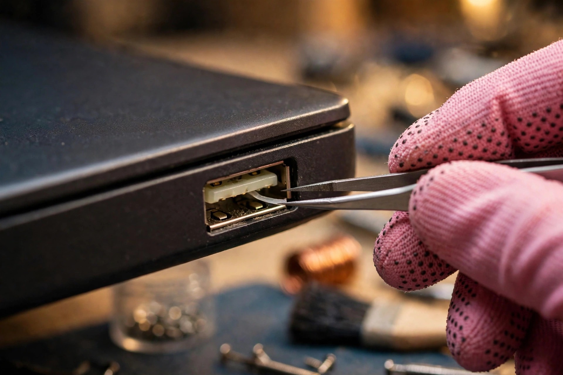
A laptop USB-A port that suddenly stops recognising a device, drops out intermittently, works only when held at one angle, or runs a USB 3 device at USB 2 speed is usually blamed first on the driver, the cable, or the motherboard. This guide focuses on one layer only: the physical layer of the full-size USB-A port on the laptop itself. By physical layer we mean the receptacle structure, the tongue, the pins, the solder joints, the shield shell and the retention structure — whether they are damaged, loose, oxidised, cracked or shorted. When the physical layer is at fault, no amount of software work will truly fix it. Conversely, when the fault is in the driver, a power-saving setting or the power arrangement, replacing the receptacle will not help either. The value of an advanced diagnosis is precisely this: locating the layer at which the fault stops, rather than jumping to a conclusion before the layers have been separated.
This guide assumes the reader has already done the most basic elimination: trying another cable, trying another device, and restarting the computer. If those steps have not been done, do them first, then use the layered method here to narrow the fault down. Every operation involving disassembly, voltage or continuity measurement, re-soldering, receptacle replacement, jumper wiring or inspection of motherboard solder joints must be left to professional inspection. Readers must not attempt them. What readers can safely do is limited to visual observation, swapping cables, devices and ports in cross-tests, checking system settings, and backing up data. If there is scorching, a burnt smell, smoke, a blackened or melted receptacle, or an abnormally hot plug, stop using that port immediately. Do not insert any further device into it and do not keep plugging and unplugging to test it.
1. Receptacle structure: what a USB-A port is made of
A USB-A receptacle can be understood from the outside in, in six parts. Knowing what each part does matters, because a broken tongue and a cracked solder joint can produce very similar symptoms while pointing to completely different repairs.
| Part | Function | Typical appearance when faulty |
|---|---|---|
| Metal shield shell | Encloses the mating assembly, providing mechanical protection, shielding and an electrostatic discharge path; the plug shell normally contacts the receptacle before the internal pins do, and the shell is generally grounded | Shell loose or deformed, shell retention solder joints cracked, plug wobbles or slips out |
| Insulating tongue | Carries the contacts on one side of the receptacle and determines insertion direction and contact position; commonly blue for USB 3.x and black or white for USB 2.0 | Cracked, chipped, broken off entirely, or sagging, with changed insertion feel and insufficient contact pressure |
| Contacts / pins | Carry power and signals; generally a copper alloy with a plating chosen to resist corrosion | Bent, missing, blackened, green, or carrying white deposits, with rising contact resistance |
| Solder tails | Connect the receptacle to the motherboard or to a USB daughter board; in surface-mount (SMT) or through-hole forms | Cracked, cold-soldered, or with lifted pads, working only at one angle or dropping out when moved |
| Retention clips / locating posts / hold-downs | Fix the receptacle to the circuit board and the case opening, sharing insertion and pull forces | Fatigued clips, cracked hold-downs, receptacle loose as a whole |
| Case opening and bracket | Limit sideways movement of the receptacle; if bracket screws loosen or the case deforms, insertion force is transmitted directly to the solder joints | Receptacle displaced, lifted on one side, cracks around the port in the case |
There are two installation forms on laptops, and they must be distinguished before any diagnosis, because the repair path is completely different. In the first form, the receptacle is soldered directly to the motherboard, so a failure usually means de-soldering the receptacle or motherboard-level work. In the second form, there is an independent USB daughter board: the receptacle is soldered to a small board, which connects to the motherboard through a flex cable or a connector, so a failure may only require replacing the daughter board. Not every laptop has a USB daughter board. On some models the USB-A port is soldered directly to the motherboard, and talk of replacing a daughter board simply does not apply. Which form a particular model uses must be checked against that model's service manual. Service documents from Dell, Lenovo and HP for individual models do contain separate USB board removal chapters, but those are examples for those models only and must not be generalised to all models.
2. Pin assignment: 4 pins and 9 pins, and why "works but slow" and "not recognised at all" are two different faults
USB-A is not a single set of contacts. A USB 3.x USB-A port is really two systems stacked together. This structure is the physical foundation of the whole layered elimination method, so it must be stated first.
USB 2.0: 4 pins
| Pin | Signal | Wire colour (standard cable) | Function |
|---|---|---|---|
| 1 | VBUS | Red | +5 V power |
| 2 | D- | White | USB 2.0 differential data negative |
| 3 | D+ | Green | USB 2.0 differential data positive |
| 4 | GND | Black | Ground / power return |
USB 3.x: 9 pins (4 pins plus 5 SuperSpeed pins)
| Pin | Signal (Standard-A naming) | Wire colour (common) | Function |
|---|---|---|---|
| 1 | VBUS | Red | +5 V power |
| 2 | D- | White | USB 2.0 data negative |
| 3 | D+ | Green | USB 2.0 data positive |
| 4 | GND | Black | Ground |
| 5 | StdA_SSRX- | Blue | SuperSpeed receive differential negative |
| 6 | StdA_SSRX+ | Yellow | SuperSpeed receive differential positive |
| 7 | GND_DRAIN | — (ground / shield return) | SuperSpeed signal ground / drain |
| 8 | StdA_SSTX- | Purple | SuperSpeed transmit differential negative |
| 9 | StdA_SSTX+ | Orange | SuperSpeed transmit differential positive |
For nominal speeds, USB 2.0 High-Speed is up to 480 Mbps, USB 3.0 SuperSpeed is up to 5 Gbps, USB 3.1 Gen 2 or USB 3.2 Gen 2x1 is up to 10 Gbps, and USB 3.2 Gen 2x2 is up to 20 Gbps but only for Type-C. These are specification nominal values. Real-world speed depends on the device, the cable, file size, hubs and system load, and must not be treated as a guaranteed measurement.
The key inference follows directly: if the basic group fails, the whole device fails; if only the additional group fails, the device still works, but only at USB 2.0 speed. Working at USB 2.0 does not mean USB 3.x is healthy, and running a USB 3 device at USB 2 speed does not mean the whole port is dead. The repair implications are completely different: the first case may involve the receptacle, solder joints or power, while the second may only involve poor SuperSpeed contact.
On power limits, at the specification level a USB 2.0 port supplies up to 500 mA and a USB 3.0 SuperSpeed port up to 900 mA. Individual manufacturers may implement higher currents, for example on a charging port, and the actual limit for a model must be taken from that model's specification; it must not be promised without verification. At the connector datasheet level, individual models list an initial low-level contact resistance of 30 mOhm maximum, an insulation resistance of 100 MOhm minimum, and a SuperSpeed differential impedance of 90 Ohm plus or minus 15 Ohm. These are values for individual models, not a universal guarantee for every USB-A receptacle, and one model's limits must not be applied to another model during diagnosis.
3. Why ports fail: five failure mechanisms
3.1 Insertion fatigue and tongue fracture or sagging
The minimum rated life for standard USB is 1,500 mating cycles. Individual USB 3.0 Type-A datasheets may rate up to 5,000 cycles, while a sealed field version may rate only 500 cycles. The correct statement is therefore that the standard minimum rating is 1,500 cycles, while actual models range from 500 to more than 5,000 cycles, depending on that receptacle model's datasheet. It must never be written as a universal claim that a USB-A port lasts exactly 1,500 cycles, and still less should a causal link between years of use and failure be inferred from age alone.
Tongue fracture follows three paths. First, angled insertion or sideways force: a plug that is not aligned, a cable pulling sideways, or a laptop dropped while a plug is inserted applies a bending moment at the root of the tongue, and the plastic tongue cracks, chips or breaks off entirely. Second, accumulated fatigue: repeated insertion extends micro-cracks at the tongue root, and once the tongue sags, contact pressure after insertion is insufficient, producing intermittent symptoms such as working only while the plug is held, or disconnecting when moved. Third, heat combined with stress may accelerate ageing of the tongue material, but the specific temperature threshold at which fracture occurs is unverified and must be taken from the manufacturer's documentation; this guide invents no such threshold.
Residual tongue fragments are a frequently overlooked risk. A fragment can jam inside the receptacle, cause a short circuit, or block insertion. If the fragment is conductive or presses on a pin, the port should be treated as a stop-use case. On insertion force, individual datasheets list a maximum insertion force of 35 N and a withdrawal force of 10 N minimum initially and 8 N minimum at end of life. The practical meaning is that insertion that is clearly too loose, with almost no resistance, or clearly too tight, requiring extreme force, is an abnormal signal. How many newtons counts as failure, however, must be judged against that model's datasheet; feel alone cannot provide a quantitative diagnosis.
3.2 Bent, oxidised and corroded pins
Pin bending is caused by angled insertion, forced reversed insertion, a deformed plug, a foreign object lifting a pin inside the receptacle, or impact from a drop. Symptoms can be inferred by pin group, but must be confirmed by measurement and must not be treated as a diagnosis on their own. If VBUS or GND is bent or broken, the device receives no power and shows no response. If D+ or D- is bent, the device may receive power but cannot enumerate, and Windows commonly shows "Unknown USB Device (Device Descriptor Request Failed)" or Code 43. If only SuperSpeed pins 5 to 9 are bent, USB 2.0 function may remain normal while SuperSpeed speed falls back to USB 2.0 or becomes intermittent.
A bent pin should not be repeatedly straightened and reused. Once a copper-alloy pin has been plastically deformed, its strength and contact pressure have changed, and there is a risk of a broken fragment remaining inside the receptacle. Whether it can be repaired must be decided by inspection, and this guide makes no general promise. Metal tools must never be used to poke at pins inside a powered receptacle, and contacts must not be abraded with sandpaper: abrasion can strip plating, bend pins, and even cause a short circuit.
Oxidation and corrosion work as follows. Once the plating on a contact surface wears through and exposes the underlying metal, oxides — which are mostly insulating — raise contact resistance, producing intermittent disconnection, speed loss or enumeration failure. Fretting corrosion is a second path: even when apparently stationary, vibration or temperature change causes tiny relative movement, described in the literature as amplitudes of a few micrometres to about 100 micrometres, which wears the plating, and the worn particles oxidise and accumulate on the contact surface. Tin plating is particularly susceptible to fretting corrosion. Gold plating resists corrosion, but gold thickness determines high-cycle reliability, ranging from flash gold at 50 to 100 nanometres to thick layers reaching 1 micrometre. Gold plating is not a guarantee of never oxidising: worn-through plating, exposed nickel or copper underneath, and surface contamination can all degrade contact.
Visual clues include pins that are blackened, green, or carrying white powdery deposits, or contact surfaces that have lost their metallic lustre. All of these are suspicious, but a normal appearance does not prove good contact; cross-testing plus measurement is still required. Dust, hair, food fragments and metal debris can lift a pin or bridge adjacent pins, causing intermittent contact or a short circuit. Any cleaning must be done with the machine powered off and disconnected, and never with a metal tool inside a powered receptacle.
3.3 Cracked solder joints, cold joints and lifted pads
Solder joint cracking is caused by mechanical load combined with thermal cycling. Insertion force, pulling and drops, together with temperature change and mismatched thermal expansion coefficients, produce fatigue cracks in solder joints. As a crack extends, intermittent open circuits appear, with symptoms such as working only at one angle or only when the receptacle is pressed lightly. A laptop-specific amplifier is that the USB-A receptacle sits at the edge of the case, so leverage from a plugged-in cable transmits torque directly to the solder joints. If the shield shell hold-downs have already loosened, all force falls on the signal solder joints, and cracking accelerates. This is a mechanistic inference; specific force values vary by model and are unverified, so they must be taken from the manufacturer's documentation.
The difference between SMT and through-hole must be stated accurately, without generalisation. SMT solder joints have a smaller area and relatively weaker shear and peel resistance, but they can be supported by hold-downs or locating posts that share the load. Through-hole tails pass through the circuit board and provide stronger mechanical anchoring, but their joints can still crack from fatigue or overload. Through-hole does not mean unbreakable, and SMT does not mean necessarily fragile. Actual life depends on joint design, retention structure, board material and usage.
A cold solder joint is one formed with insufficient heat, where the solder did not fully melt or wet properly, leaving a rough, dull surface that is weak and prone to cracking. A cold joint may be a manufacturing defect or the result of poor rework. Its typical symptom is also intermittent contact, and visual inspection alone may not confirm it; magnified inspection plus measurement is required. Related defects in the same family include insufficient solder, open or virtual joints where solder did not adequately wet pad and lead, and solder bridges shorting adjacent joints. All should be checked together during diagnosis.
Pad lifting means a copper pad separates from the circuit board substrate under mechanical or thermal stress, breaking the electrical connection. A lifted pad that touches a neighbouring component or trace can also cause a short circuit. Causes include excessive heat or prolonged heating during soldering, moving a component during de-soldering, and repeated mechanical pulling. After pad lifting, jumper-wire or trace repair may be needed, and difficulty and feasibility depend on the extent of lifting, trace damage and board layer structure. This guide promises no repair success rate; the actual machine must be inspected.
Inspection pointers include a receptacle that moves as a whole, can be rocked, lifts on one side, or shows discolouration or cracks in the board around the joints. All are suspicious, but the final judgement requires disassembly, visual inspection and measurement. Rocking the receptacle from outside alone cannot settle it.
3.4 Loose shield shell: from lost retention force to cascading damage
A loose shield shell produces very specific symptoms: a plug that wobbles sideways far more than in other ports on the same machine, slips out easily, is recognised only while held by hand, or disconnects intermittently. The mechanism is cracked shield hold-down solder joints, fatigued retention clips, a worn case opening, or loosened bracket screws, so the receptacle loses its grip. As grip falls, contact pressure falls too, and intermittent symptoms follow.
The cascading effect deserves explicit statement. Once the shell is loose, insertion force is no longer shared by the shell, so signal solder joints and the tongue bear additional stress, accelerating solder cracking and tongue damage. The shell is generally grounded, providing electrostatic discharge and shielding. A loose shell or poor grounding may reduce interference immunity, but the quantitative relationship between a given degree of looseness and shielding loss is unverified and must be taken from the manufacturer's documentation; this guide invents no such figure. For checking, power off and disconnect, then insert the same plug into each port on the same machine and compare tightness. Rocking the receptacle alone, without a plug inserted, is easy to misjudge and must be combined with functional testing.
3.5 Foreign objects and short circuits: the 5 V to ground risk
A short circuit can arise in several ways: a bent pin touching an adjacent pin or the shield shell, a tongue fragment plus metal debris bridging VBUS (pin 1) to GND (pin 4) or to the shell, conductive residue left after liquid ingress, or a solder bridge across joints. Moisture can cause an immediate short circuit or long-term corrosion of contact surfaces, and corrosion products may be insulating, raising resistance, or conductive, accumulating until they bridge adjacent terminals.
The principle and limits of host overcurrent protection must be stated without over-promising. The USB 2.0 specification requires hosts and self-powered hubs to implement overcurrent protection and to be able to detect an overcurrent condition and report it to USB software. If the total current of a group of downstream ports exceeds a preset value, the overcurrent protection circuit cuts or reduces power to the affected ports. At the Windows level, visible signals include a "Power Surge on the USB port" notification and ports being shut down. Overcurrent protection does not, however, guarantee that no short circuit can cause damage. The protection device may be a self-resetting fuse, a current-limiting switch, or current limiting inside the controller, and its trigger threshold, response time and whether protection is shared across a group vary by model. A VBUS-to-signal short circuit or externally applied high voltage may fall outside the protection range. This guide does not promise that protection makes short circuits harmless.
The safety warning must be retained without dilution. On seeing scorching, a burnt smell, smoke, a blackened or melted receptacle, or a hot plug, stop using that port immediately, do not insert any further device, and do not keep plugging and unplugging to test it. If a short circuit or liquid ingress is suspected, power off, remove the power supply and the battery if it can be safely removed, and do not clean the receptacle with a metal tool while powered. If the same port has triggered an overcurrent warning or shut down a whole group of ports, treat it as awaiting repair, not as fixed by a restart. These are general safety recommendations, not a judgement about the extent of damage in any individual case; actual damage must be confirmed by inspection.
3.6 Symptom table: inference from phenomena, not a diagnosis
| Symptom | Primary physical suspicion | Also rule out |
|---|---|---|
| Plug extremely loose, slips out, works only while held | Loose shield shell, sagging tongue, fatigued retention | Deformed plug itself |
| Disconnects when moved, works only at one angle | Cracked solder joint, sagging tongue, rising contact resistance | Internal break in the cable |
| Power but no data (light on, device not recognised) | D+ / D- bent, oxidised or broken | Driver, descriptor request failure |
| No power and no response | VBUS / GND broken, solder joint open | Controller, power management, overcurrent protection already triggered |
| USB 2 speed only | Poor SuperSpeed contact on pins 5 to 9 | Cable, hub, driver |
| Overcurrent warning on insertion, whole group of ports shut down | VBUS to ground short circuit, debris bridging | Overloaded device itself |
| Scorching, burnt smell, overheating | Short circuit, local heating from high contact resistance | — (stop using immediately) |
4. Layered elimination: five layers, in order, without skipping
The principles are only two: work from outside to inside, from easy to hard, changing one variable at a time; and stop immediately if any safety warning sign appears. Before cross-testing, run the lowest-cost, highest-information 2x2 comparison.
| Another USB-A port on the same laptop | Another computer | |
|---|---|---|
| Same device and same cable | Works: suspect the original port. Still fails: suspect device, cable, or a shared system cause | Works: suspect the original laptop. Still fails: suspect the device or cable itself |
| Another device and another cable | Works: points further to the original device or cable. Still fails: points further to the port or system layer | — |
Layer 1: Physical layer (receptacle, contacts, tongue, retention force)
Need a laptop repair expert?
Free diagnosis · Transparent pricing · No fix, no fee · 180-day warranty
What readers can check is limited to appearance and feel, and must not involve poking a metal tool into the port. Is the plug loose, wobbly, or repeatedly backing out slightly after insertion? Does moving the plug gently sideways cause the device to disconnect and reconnect immediately? Is the blue or black tongue inside the port cracked, bent or chipped? Are the metal contacts visibly bent, blackened, green, or carrying corrosion or dust or debris? Is the outer frame deformed or pushed inward? Are there cracks in the case around the port, which may indicate impact or long-term force? Compare insertion feel with another USB-A port on the same machine: a healthy port should offer clear resistance and a positive catch, while a port so loose that a plug slides in with zero resistance usually indicates fatigued internal springs or a loosened retention structure.
Only after this layer can the statement be made that the port looks normal, inserts firmly, and is unaffected by angle. Until that statement can be made, do not rush to the driver layer.
Layer 2: 5 V power layer (VBUS, current limits, overcurrent protection)
The specification facts were given in Section 2: up to 500 mA per USB 2.0 port and up to 900 mA per USB 3.0 port, at a nominal 5 V. An unpowered hub must share the upstream port's power among all downstream devices; only a self-powered hub can supply each port in full. A high-power device, such as a mechanical external hard drive at spin-up, may demand current close to or above the USB 2.0 500 mA limit, with the result that the light appears on and the device is briefly recognised, but reading or writing fails or the device disconnects.
| Observation | Why it points to the power layer | Evidence against a power cause |
|---|---|---|
| Low-power devices (mouse, keyboard, USB flash drive) work, high-power devices fail on the same port | Power ceiling: low-power devices pass, high-power devices do not | If even a mouse fails, the cause is more likely physical, signalling or controller |
| Device light on, system briefly recognises it, then disconnects on read, write or spin-up | Current demand rises at spin-up or load, voltage falls or protection trips | If it disconnects even when idle, physical contact or a power-saving setting is more likely |
| Fails only through an unpowered hub or dock, works when plugged directly | The hub dilutes power; direct connection bypasses the sharing problem | If direct connection fails identically, do not blame the hub |
| Fails only when two high-power devices are used together, works singly | Combined current demand exceeds the port or hub supply capability | If it fails singly, it is not a case of two devices together exceeding the limit |
| System reports that a USB device has exceeded the power limits of its hub port, or a similar power message | Directly points to the power layer | Absence of a message does not exclude a power problem; many cases of insufficient power show only as disconnection |
What only professional inspection can do includes measuring whether VBUS voltage falls outside its tolerance, checking whether overcurrent protection components have tripped or been damaged, and checking power circuitry for poor joints or scorching. All of these involve disassembly and measurement and must be left to professional inspection. The important reminder is that insufficient power does not equal a faulty motherboard. Often the device simply draws more than the port can supply, and the solution is a different power arrangement — direct connection, a powered hub, or device power — rather than a motherboard replacement. Misjudging this as a motherboard fault is one of the misdiagnoses in Section 6.
Layer 3: USB 2.0 / 3.x signalling layer (D+ / D-, SuperSpeed contacts, cables, speed fallback)
The key distinction was already stated: working at USB 2.0 does not mean USB 3.x is healthy. When SuperSpeed contacts are poorly connected, oxidised, bent, or when the cable carries only USB 2.0 cores, the system gracefully falls back to USB 2.0 mode. The device still works, only slowly. In Windows Device Manager or device information, "High-Speed" means USB 2.0 (480 Mbps) and only "SuperSpeed" means a USB 3.x link. Readers should be taught to read that wording, not to judge only by a feeling of how fast copying seems.
| Observation | Judgement within this layer |
|---|---|
| A USB 3.x flash drive or SSD runs only at USB 2.0 speed on one port, but reaches SuperSpeed on another port or another computer | The SuperSpeed contacts, cable, or upstream path of that port is at fault; change the cable first, then the port, one at a time |
| All USB 3.x devices fall back to USB 2.0 on all ports, while USB 2.0 devices all work normally | Points to the controller, xHCI, driver or BIOS layer, not to a single physically broken port |
| One device runs only at USB 2.0 speed on every computer | Points to the device itself or the SuperSpeed part of its cable |
| Transfers repeatedly break, but low-speed devices (mouse) work perfectly | High-speed signals are more sensitive to contact and interference; low-speed devices use D+ / D- and not SuperSpeed, so they are unaffected — a diagnostically valuable contrast |
| SuperSpeed is achieved only by adjusting the angle, and falls away when moved | Typical of poor SuperSpeed contact; final confirmation still requires professional inspection, and readers must not poke at contacts with tools |
Manufacturer documentation also lists other causes of a USB 3.0 device falling back to USB 2.0 speed: insertion that is too slow, so the detection window during insertion is missed; xHCI disabled in BIOS; an outdated or damaged driver; a cable that supports only USB 2.0; and a device that supports only USB 2.0. Advising readers to remove the plug and reinsert it smoothly in one motion is reasonable, but if the problem repeats, contacts or the cable should be suspected.
Layer 4: Controller / xHCI layer (host controller, hubs, BIOS settings)
xHCI (eXtensible Host Controller Interface) is the interface standard for USB 3.x host controllers. If xHCI is disabled in BIOS or UEFI, USB 3.x ports will operate in USB 2.0 mode, no matter what Windows is set to. This is a typical system-layer cause of a whole group of ports being slow together, and it must not be misjudged as all ports being physically broken at once.
Typical phenomena at this layer include several ports under the same controller failing together — for example, two ports on the left side slow or unrecognised together while a port on the right works normally — which may indicate the controller, the upstream circuitry of that group, or a BIOS setting. A single physically broken port rarely appears as a group failure. If all USB ports fail at once, including USB-C depending on the model design, the controller, chipset, power bus or system layer is more likely, rather than ports failing one by one. On individual models, USB-A and USB-C may share a controller or use separate controllers, and the actual grouping must be taken from that model's service manual; this guide does not fix which port follows which controller without verification. If the USB host controller in Device Manager shows a yellow warning, has disappeared, or shows "Unknown USB Device", that message alone is very general. It may be a driver problem or a hardware problem, and no conclusion can be drawn from a single error code. If problems began after a BIOS or chipset driver update, a driver or firmware regression or a manufacturer-known issue should be considered. BIOS operations carry risk, so this guide only advises readers to follow the manufacturer's official instructions with stable power, and never to flash BIOS casually.
Reader checks at this layer, without disassembly, are to record which ports fail and which work, and look for a group pattern; to check whether USB or xHCI settings in BIOS or UEFI have been disabled, looking only and changing only as the manufacturer's documentation directs, and backing up data before any change; and to download chipset or USB controller drivers from the laptop brand's official support site for that exact model, never from a driver tool of unknown origin. What only professional inspection can do includes checking the controller chip, surrounding components and motherboard circuitry. If the controller itself is suspected to be damaged, repair options and cost must be decided from inspection results, and must not be declared as a motherboard replacement before inspection.
Layer 5: Driver / system layer (Windows drivers, power saving, selective suspend, sleep and wake)
USB Selective Suspend is the most common false physical fault. An external hard drive may enter selective suspend and be treated by the system as unresponsive, and turning off the USB selective suspend setting can prevent an external hard drive from being powered down. The official Microsoft path is: Control Panel or power plan, change plan settings, change advanced power settings, USB settings, USB selective suspend setting, and set both "On battery" and "Plugged in" to "Disabled". A related setting is found in Device Manager, for each USB Root Hub, Properties, Power Management, unchecking "Allow the computer to turn off this device to save power".
The typical time pattern of a selective suspend or sleep-and-wake problem is clean: normal while in use, failure only after a period of idling, closing the lid, or waking from sleep, with recovery after re-plugging or restarting. Physical damage does not follow such a clean time pattern. Physical looseness is usually linked to movement, not to idling or sleep.
Typical driver-layer phenomena include a yellow warning in Device Manager, Code 43 (Windows has stopped the device because it reported a problem), or "Unknown USB Device (Device Descriptor Request Failed)". Code 43 itself is very general. It may be a genuine hardware problem or only a driver problem. This guide states plainly that Code 43 does not mean the port is broken, and does not mean it must be a driver fault either. It only means Windows has stopped the device, and cross-testing is needed to separate the causes. If all ports fail together after a Windows update or driver update, after previously working normally, the driver or system layer becomes more suspect, but hardware problems newly exposed by the update must also be excluded, and causality must not be asserted without verification.
The enumeration principle is worth a brief explanation, because it explains why poor D+ / D- contact produces enumeration failure. The host, through the hub driver, issues a device descriptor request (GET DESCRIPTOR) to identify the device. If D+ / D- contact is poor, the descriptor request may fail, and Windows shows an enumeration failure message. If a port is in overcurrent, reset completion may be ignored and retried as appropriate, which explains why Device Manager status can change repeatedly after an overcurrent event.
Reader checks at this layer are to perform a genuine restart, not a wake from sleep, and see whether the problem disappears; to check Device Manager, under Universal Serial Bus controllers, for yellow warnings; to update or reinstall controller drivers as the manufacturer directs, without deleting system devices that are not understood; to turn off USB selective suspend by the official Microsoft path, then repeat an idle and wake test; and to check Windows Update and the brand's official drivers for pending USB or chipset driver updates.
The layered summary below can be used directly for comparison:
| Layer | One-sentence judgement | Strongest single piece of evidence |
|---|---|---|
| 1 Physical | Movement and angle affect everything | Works only at one angle, disconnects immediately when moved; insertion feel clearly looser than another port |
| 2 Power | Low-power devices work, high-power devices do not | Works when plugged directly, fails only through an unpowered hub; disconnects at read, write or spin-up |
| 3 Signalling | USB 2.0 works, USB 3.x does not | Device shows High-Speed rather than SuperSpeed; speed recovers after changing cable or port |
| 4 Controller / xHCI | A group of ports fails together | Several ports in the same group share the same symptom; BIOS xHCI disabled; controller missing or warned in Device Manager |
| 5 Driver / system | Time pattern tied to sleep or idling | Fails only after sleep or idling, recovers on re-plugging or restart; problem disappears after turning off selective suspend |
5. Hong Kong conditions: why USB-A ports here are especially vulnerable
The conditions below are all written as risk factors plus observation methods, not as absolute claims that Hong Kong must cause a particular outcome. Sealing, plating and materials for individual models are governed by the manufacturer's documentation.
Humidity, salt mist and condensation from temperature change: contact corrosion
Hong Kong Observatory climatological normals for 1991 to 2020 give an annual mean relative humidity of 78% and annual rainfall of 2,431.2 millimetres. In other words, Hong Kong is in a high-humidity environment for much of the year, and metal contacts inside ports are exposed to humid air over long periods. Case analysis of severe printed circuit board corrosion in South China, Hong Kong and Japan found corrosion products containing mainly sulphur and chlorine. When air conditioning is switched off at night, room temperature may rise from 20 degrees Celsius at 50% relative humidity during the day to about 30 degrees Celsius at 80 to 85% relative humidity, with a dew point of about 26 degrees Celsius, so condensation forms on cold circuit board surfaces, and water containing electrolytes is sufficient to conduct and accelerate corrosion.
This mechanism transfers directly to the laptop case. After use in an air-conditioned room during the day, the machine is taken home or into a non-air-conditioned environment at night, and if the body and ports are colder than the dew point, condensation may form inside the port. Over a long period, the finer SuperSpeed contacts, which are smaller and deeper inside the port than USB 2.0 contacts, may be more likely to be affected by oxidation. Connector environmental performance literature states that moisture ingress affects insulation performance and corrodes metal parts, and that in environments containing water and salt, metal structures and contact surface platings may suffer electrochemical corrosion, affecting physical and electrical performance. Hong Kong is near the sea, so salt mist cannot be ignored, but the distance from the sea that counts as high risk is unverified, and this guide invents no distance figure.
Observation points are contacts inside the port that are blackened, green, or carrying white powdery material; devices that work intermittently without obvious looseness; and problems that worsen in humid seasons, around the return of damp spring weather, and improve on dry days. All are indirect clues to corrosion or poor contact, and final confirmation still requires professional inspection. Prevention should be written safely and without exaggeration: cover ports when not in use, if the model has covers; avoid inserting and removing plugs immediately after rapid transitions between air-conditioned and hot, humid outdoor conditions; and if a port has been wetted or is visibly damp, do not power it up immediately — have it checked professionally first. Readers must not be taught to polish contacts with any liquid, sandpaper or metal tool.
Frequent commuting insertion and removal: wear and spring fatigue
Hong Kong commuters may insert and remove flash drives, mouse receivers, phone cables and docks many times a day, accumulating a high count over a year. How many insertions per day convert into how many years of life, however, depends on actual insertion technique, and no false lifetime-in-years calculation should be made without verification. Angled insertion, blind one-handed insertion, stuffing a laptop into a backpack with a device still plugged in, and knocking a plugged-in receiver against a desk edge are typical Hong Kong commuting actions that accelerate wear. A guide should name these actions specifically, so readers can recognise their own habits.
The consequence of spring fatigue is not only looseness. As contact pressure falls, contact resistance rises, and high-speed signals fail first — speed falls and connections drop — while low-speed devices may still work, misleading the user into thinking the port is not really broken and needs no attention. This is exactly the Layer 3 signalling presentation. Under commuting conditions, long-term angled insertion, dragging a dock around, and repeatedly knocking a plugged-in flash drive or receiver can wear a port far faster than laboratory rated conditions, but the specific acceleration factor is unverified, and this guide invents no multiplier.
Adapters and docks under long-term leverage: the most easily overlooked physical killer
A USB-A port is not designed to bear weight. A heavy dock or a rigid adapter left plugged in long-term, or a flash drive plus a thick, stiff cable, turns the plug into a lever: gravity and pulling force act on the receptacle and solder joints over a long period. Typical Hong Kong scenes include a laptop on a narrow cafe table with a dock hanging off the side of the machine, a flash drive left plugged in inside a backpack so that pressure on the backpack presses the drive against the port, and a dock rocking with the machine whenever the machine moves.
The chain of consequences is clear: the receptacle loosens, solder joints bear force, poor joints or cracked joints appear, connections become intermittent, and finally the port fails completely. This process can drag on for a long time, and the fact that moving the plug makes it work again in the middle of the process can mislead users into thinking it is a driver problem. Prevention is straightforward: remove docks when not in use; connect docks with short, flexible cables, so the whole weight of the dock does not hang from the port; rest docks on the table surface for support, never suspended; and never leave devices plugged in inside a backpack. As a diagnostic hint, if a problem began on the port that long carried a particular heavy dock, while other ports remain normal, leverage-induced physical damage becomes more likely, and the receptacle and solder joints should be checked by professional inspection.
Local parts and repair reality
A USB-A receptacle is itself a standard part, but height, pin layout, retention method, and whether it connects by flex cable or is soldered directly to the board vary by laptop model and must be matched by model. A generic USB receptacle will not necessarily fit, and this guide must state that matching is by model and must not tell readers to buy a receptacle and replace it themselves. Some slim laptops have USB-A ports soldered to the motherboard, while others connect through a small daughter board or flex cable, and repair difficulty and risk are completely different. Which design applies to which model is governed by that model's service manual. Before verification, this guide must not state that all machines are soldered to the motherboard or that all machines can have a daughter board replaced.
Local repair realities, without any specific price, since USB repair prices are always subject to a written quotation after inspection, are as follows. If a receptacle is in stock and the pads are intact, that is usually the most direct repair path. If pads have lifted or traces have broken, jumper-wire repair may be needed, with higher difficulty and risk, and professional inspection must assess whether it is worth doing. If surrounding components such as power or protection devices are damaged, the work may fall into the motherboard chip-level repair category and must be assessed separately. If the controller chip is damaged, board replacement may be involved, with the highest cost and risk, to be considered together with the age and remaining value of the whole machine. On data safety: back up data before sending a machine for repair. Do not assume that data on an external hard drive will simply be recoverable once the port is fixed. Confirm first whether the data has another backup copy.
6. Common misdiagnoses and traps
| # | Misdiagnosis | Truth and how to distinguish | Correct action |
|---|---|---|---|
| 1 | On seeing a device not recognised, treat it as a driver or system problem and keep reinstalling drivers | The driver layer is only one of five layers; physical looseness, insufficient power and faulty signal contacts can produce the same message. Code 43 itself is very general and may be hardware or driver | Run cross-tests first: change port, cable, device and computer. Only after all four tests, talk about drivers |
| 2 | A USB 3.x device falling back to USB 2.0 speed means the port is completely dead | USB 3.x is backward compatible: plugging into a USB 2.0 port, using a USB 2.0 cable or hub, poor SuperSpeed contact, or xHCI disabled can all cause fallback, while USB 2.0 function may be completely normal | Check whether the device shows SuperSpeed or High-Speed; change cable, then port, then check BIOS xHCI; do not condemn the port on speed alone |
| 3 | A high-power device not working means the motherboard is faulty | USB 2.0 is limited to 500 mA per port and USB 3.x to 900 mA per port; an unpowered hub shares power; a mechanical hard drive draws most at spin-up and is most likely to fail at the power margin | Direct-connection test, powered-hub test, single-use test; if all three point to the power layer, solve the power arrangement first, not the motherboard |
| 4 | A device not working on this machine means the port is faulty | The device itself may be faulty, the cable may be faulty, or the SuperSpeed part of the device may be faulty, all of which appear on this machine as a port problem; but if the same device fails identically on another computer, the device or cable is implicated | Verify the device and cable on another computer; if they behave the same there, suspect the device or cable first, not the laptop |
| 5 | One bad port means all ports are bad, or the motherboard is faulty | Physical damage to a single port usually affects only that port; all ports failing together points first to the controller, power bus, driver or system layer. Conversely, a group of ports failing together does not mean ports are failing one by one, but may share a common cause | Record which ports fail and which work; a single bad port, focus on that port; a group or all ports failing, work through Layers 4 and 5 |
| 6 | Failure after sleep or idling means poor contact | Selective suspend and sleep-and-wake problems have a clean time pattern: normal while in use, failure only after idling or sleep, recovery on re-plugging or restarting | Turn off USB selective suspend by the official path, then repeat an idle and wake test; if the problem disappears, it is not physical damage |
| 7 | A blue port must be USB 3.x high speed; a black port must be slow | A blue tongue is only a convention, and individual manufacturers may use other colours; true distinction requires the SS mark, pin count and actual link speed, not colour alone | Look at all three together: colour, SS mark, and the speed shown in Device Manager |
| 8 | The tighter and harder the insertion, the better; a loose port can be wedged tight | Excessive force, angled insertion, or wedging foreign objects into a port may bend contacts, crack the tongue, or even cause a short circuit, turning mere poor contact into receptacle damage | Insert smoothly, in one motion; if loose, deformed, or containing debris, stop using that port and have it professionally inspected, rather than poking, wedging or polishing it |
| 9 | If changing drivers or reinstalling the system does not help, the motherboard must be replaced | After the driver and system layer is excluded, the physical, power, signalling and controller layers remain; "software methods have all been tried" only proves it is not a software problem, not which hardware problem it is, and certainly not that the motherboard must be replaced | Narrow down layer by layer using the layered table; motherboard replacement is one of the last options, not the default answer |
| 10 | Failure through a hub or dock means the laptop port is faulty | An unpowered hub dilutes power and bandwidth, and the hub's own USB 2.0 or 3.x specification and its cable can cause speed loss or disconnection; normal direct connection already excludes the laptop port | Always run a direct-connection comparison first: if direct connection works, the problem is in the hub, cable or power, not the laptop port |
7. Reader safety checklist (no disassembly version)
Everything below is safe for readers to do. Work through it in order, and record the result of each step:
1. Look: port appearance, tongue, contact colour, insertion feel; compare with another port.
2. Change port: with the same device and cable, try every USB-A port on the machine, and record which ports work and which do not.
3. Change cable: try another cable known to be good and of matching specification; a USB 3.x device needs a USB 3.x cable.
4. Change device: try a low-power device, such as a wired mouse, in the same port, to see whether all devices fail or only high-power devices fail.
5. Change computer: try the same device and cable on another computer, to exclude a fault in the device or cable itself.
6. Plug directly: remove hubs and docks, and plug the device directly into the laptop port.
7. Power comparison: use the high-power device alone, with a powered hub, and in a USB 3.x port, and record each result separately.
8. Speed comparison: for a USB 3.x device, check whether it shows SuperSpeed or High-Speed; when slow, change cable, then port, and check again.
9. Restart and drivers: perform a genuine restart; check Device Manager for yellow warnings; update chipset and USB drivers from the brand's official site.
10. Power-saving comparison: turn off USB selective suspend by the official path, then repeat an idle, sleep and wake test.
11. Back up: while a port or power supply is suspected to be unstable, do not use that port as the only backup route; back up important data first through another healthy port or over the network.
12. Stop-use rule: if the port is visibly deformed, smells burnt, overheats abnormally, or sparks or smells odd on insertion, stop using that port immediately, do not test it further, and have it professionally inspected.
If step 12 still leaves the problem unresolved, or if step 1 already shows obvious physical damage, there is no need to continue testing. Go directly to professional inspection, and take the records from steps 1 to 11 with you; they can save the inspector considerable time.
8. Repair, replace or work-around decision framework
The decision principle is: first fix the layer, then fix the part, then fix the value. That is, first use Section 4 to determine the layer, then let professional inspection determine which part is faulty — receptacle, solder joint, pad, trace, component or controller — and only then compare repair cost with the remaining value of the whole machine, the value of the data, and the alternatives. Talking about whether to replace the motherboard before the layer is fixed is the most common decision error.
| Option | When it applies (after professional inspection confirms) | Advantages | Risks and limits |
|---|---|---|---|
| Replace the receptacle | The receptacle itself is damaged (cracked tongue, fatigued springs, bent or broken contacts) and the pads are intact | Most targeted; retains the original motherboard and other functions | The receptacle must be matched by model; soldering quality affects service life |
| Re-solder (rework the original receptacle) | The receptacle is intact and only solder joints are cracked or poorly jointed | No part replacement needed; retains the original receptacle | If the receptacle itself is already fatigued, re-soldering may loosen again soon; if the cause of cracking (for example long-term leverage) is not removed, it will crack again |
| Jumper wire (repair broken traces) | Pads have lifted or motherboard traces have broken, but the controller and surrounding components are normal | Can save a board whose pads are already damaged | High difficulty and demanding handwork; trace layout is constrained; may break again under future force |
| Replace the board (motherboard or daughter board) | Controller damaged, multiple traces damaged, repair cost already close to board replacement cost; or the model's port sits on a daughter board, where replacing the daughter board is more reasonable than soldering the motherboard | Solves multiple problems at once | Highest cost; may involve system boot, licensing and data migration issues, to be assessed by model |
| Use other ports or a dock (work-around) | The faulty port is confirmed as a single physical failure and other ports are normal; or repair cost already exceeds the remaining value of the machine; or the reader urgently needs to resume work | Immediate resumption of use; no disassembly; usually lowest cost | Symptomatic only: the faulty port remains faulty; long-term reliance on a dock increases force on another port, and leverage must not simply be transferred to another port |
1. Single physically faulty port, other ports normal, machine still relatively young, and data and work depend on the machine: prioritise receptacle replacement or re-soldering, subject to professional inspection results. At the same time, remove the force cause, and do not keep a dock hanging from the port long-term.
2. Single physically faulty port, but the machine still has other healthy USB-A ports plus USB-C ports, and work is not urgent: a work-around can be used for now, while the machine is taken for inspection and quotation, before deciding whether to repair. Do not, however, leave it indefinitely just because other ports still work. If a bent contact inside the faulty port is causing intermittent short circuits, delay may affect surrounding circuitry, so if a short circuit is suspected, have it inspected early.
3. A group of ports or all ports failing: do not jump directly to board replacement. Work through Layers 4 and 5 first (BIOS xHCI, drivers, selective suspend), then let professional inspection separate controller, power bus and system layer causes.
4. Lifted pads or a need for jumper wiring: let professional inspection assess the extent of breakage and the likelihood of success, then compare with the remaining value of the whole machine and the value of the data. If inspection judges success unlikely or re-breakage likely, a work-around or machine replacement may be more reasonable.
5. Controller damage or a need for board replacement: a written quotation must be obtained, and considered together with machine age, the condition of other parts such as battery and screen, and data migration cost. USB repair prices are always subject to a written quotation after inspection, and this guide provides no estimate.
6. Machine already old, with multiple ageing parts, for example battery, screen and keyboard problems at the same time: consider USB repair as part of a whole-machine assessment, not as an isolated decision about one port. Prices for other parts on the site apply to those parts only and must not be transferred to USB repair for comparison.
When repair is not worth doing, the guide must say so, not only promote repair. Examples include professional inspection confirming controller damage where the written quotation already approaches or exceeds the reasonable remaining value of the whole machine; pad or trace damage so extensive that inspection judges re-breakage likely after repair; a discontinued model where receptacle or daughter board parts are hard to find and waiting time would seriously affect work, while a work-around (other ports plus a dock) already meets working needs; and a reader who is already planning to replace the machine, where the USB port problem is only one of several reasons for replacement rather than the sole reason. In any of these cases, the basis must be the written assessment from professional inspection, and readers must not decide on appearance alone that repair is not worth doing and skip inspection.
The trade-offs of upgrade and alternative options must state disadvantages as well as advantages, not advantages only:
| Alternative | Suitable when | Watch out for |
|---|---|---|
| Another USB-A port on the same machine | One port faulty, others normal | Spread insertion counts evenly; do not concentrate all devices long-term on the same port |
| A USB-C port plus an adapter or dock | The machine has a healthy USB-C port; more ports or high speed are needed | Adapters are themselves consumables and force points; choose an adapter of matching specification; a heavy dock left hanging will transfer the leverage problem to the USB-C port |
| A self-powered USB hub | Many high-power devices, not enough ports | Check the hub's power and speed specifications carefully; an unpowered hub cannot solve insufficient power |
| Replacing the machine | Multiple ageing parts, repair quotation too high, upgrade already planned | Back up data before replacement; data migration and disposal of the old machine need separate handling |
9. Worked teaching scenario (not a real case, for illustration only)
The following scenario is a teaching illustration. It is not a real case. There is no real customer and no real repair record, and the sequence is hypothetical, provided only to demonstrate how the layered method is used to think. Suppose a laptop's left USB-A port drops an external hard drive intermittently, while the right port is normal. A mouse works normally in the left port, and the external hard drive is stable when plugged directly into the right port. By the layered method: first, the group pattern already excludes a shared controller or driver cause, because the right port is normal. Second, low-power devices work while high-power devices fail, pointing to the power layer or to a physical contact problem in the left port, which still need to be separated. Third, the direct-connection test has already excluded the hub, leaving the left port itself. Fourth, on inspecting the left port, if the tongue is intact but insertion is clearly looser than in the right port, loose shield shell or solder joint problems become more likely, but final characterisation still requires professional inspection and must not be decided from the illustration as receptacle replacement or re-soldering. The point of the illustration is to demonstrate the narrowing sequence, not to conclude without inspection.
A second illustration: suppose a USB 3 flash drive runs only at USB 2 speed in all ports, but reaches SuperSpeed on another computer. The group pattern plus the cross-computer comparison has already moved suspicion away from a single port and towards the controller, xHCI, BIOS or driver layer. Replacing a receptacle at that point would be the wrong direction. The illustration again reminds readers that when a group of ports fails together, Layers 4 and 5 come first, and board or receptacle replacement must not be jumped to.
10. Preparing for inspection, and related links
Before inspection, prepare the following information: which ports fail and which work; which device and cable combinations fail; direct-connection versus hub comparison results; whether speed shows as SuperSpeed or High-Speed; whether failure occurs only after idling or sleep; and whether the port shows deformation, scorching or debris. Take the failing device and cable to the inspection, so they can be compared on the spot. Back up important data before inspection, and do not use a suspected unstable port as the only backup route.
USB repair itself is always subject to a written quotation after inspection, and this guide provides no USB repair estimate. For general pricing reference and inspection arrangements, see https://www.laptops-king.com/pricing ; for the inspection process, see https://www.laptops-king.com/diagnostic . Shop information: Room 1209, Daly Plaza, Shek Mun, Shatin, telephone +852 2186 8010, WhatsApp +852 6558 6806, business hours 12:00-19:00.
Finally, the safety line is repeated: disassembly, measurement and soldering are for professional inspection only, and readers must not attempt them; on seeing scorching or a burnt smell, stop using the port. Facts that are unverified are written in this guide as possible, pointing to, or subject to the manufacturer's documentation. A particular model's receptacle model, tongue material grade, plating thickness, hold-down count, whether it sits on an independent daughter board, daughter board part number, port grouping, and power ceiling are all governed by that model's service manual or specification documents. Do not conclude from appearance, colour, age or a single test that a port, motherboard or driver must be faulty. Work through the layers, and the evidence will itself show which layer the fault stops at.
Frequently asked questions
Q1: A USB device is completely unrecognised. Does that necessarily mean the port is broken?
A: No. Complete non-recognition can arise at the physical layer (VBUS or GND broken, solder joint open), the power layer (overcurrent protection already triggered), the signalling layer (D+ or D- broken), the controller layer, or the driver layer. Cross-testing must come first: change port, cable, device and computer, and only after all four tests can the fault be narrowed. A single port failing while others work points more towards that port; all ports failing together requires the controller and driver layers first, and must not be judged as a broken port directly.
Q2: A USB 3 device runs only at USB 2 speed. Does that mean the port is completely dead?
A: No. USB 3.x is backward compatible, so plugging into a USB 2.0 port, using a USB 2.0 cable or hub, poor SuperSpeed contact, or xHCI disabled in BIOS can all cause fallback to USB 2.0, while USB 2.0 function may be completely normal. The correct approach is to check whether the device shows SuperSpeed or High-Speed, then change the cable, then the port, then check BIOS xHCI, and not to condemn the port on speed alone.
Q3: A plug is very loose and works only while held. Can it be fixed with glue or by wedging something into the port?
A: No. Looseness may be caused by a loose shield shell, a sagging tongue, or fatigued retention clips. Fixing it with glue, wedging foreign objects, or prying the tongue up yourself may bend contacts, crack the tongue, or even cause a short circuit, turning mere poor contact into receptacle damage. If a port is loose, deformed, or contains debris, stop using that port and have it professionally inspected, so that the receptacle, solder joints and pads can be checked to determine what is faulty, before deciding on receptacle replacement or re-soldering.
Q4: One USB-A port is broken. Must it be repaired immediately, or can other ports be used instead?
A: It depends. If a single port is physically faulty, other ports are normal, and work is not urgent, a work-around can be used for now while the machine is taken for inspection and quotation, before deciding whether to repair. It must not, however, be left indefinitely just because other ports still work, because a bent contact inside the faulty port causing intermittent short circuits may affect surrounding circuitry if delayed. If a group of ports or all ports fail, or if there is scorching, a burnt smell or abnormal heating, do not rely only on a work-around. Stop using the port and have it professionally inspected. USB repair prices are always subject to a written quotation after inspection.
Need Professional Laptop Repair?
Laptop King has 15+ years of repair experience in Shek Mun, Sha Tin. Free diagnosis, transparent pricing, no fix no fee. 180-day warranty for your peace of mind.