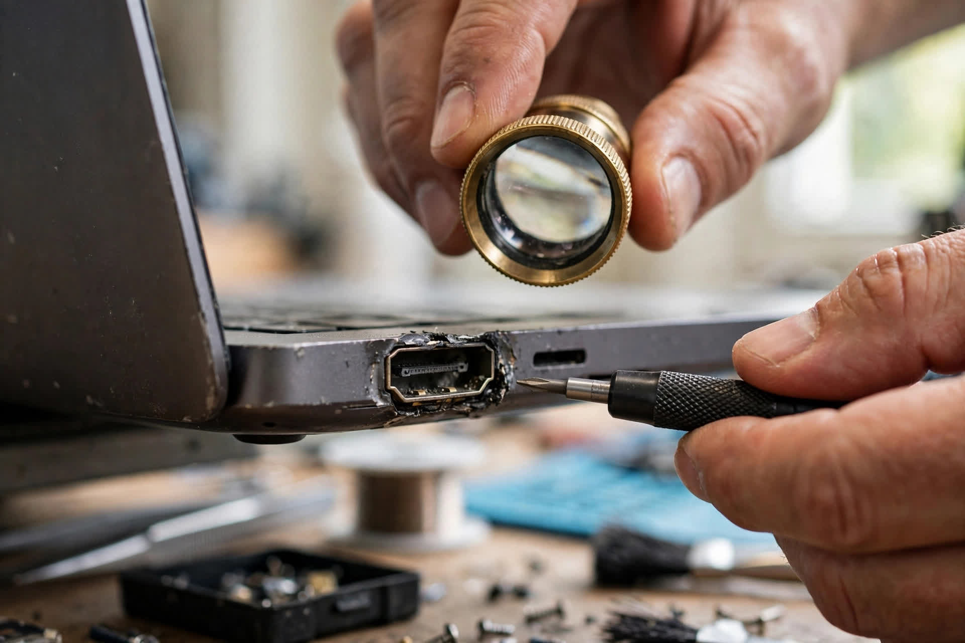
An external display that suddenly shows no picture, flickers intermittently, only works when the cable is moved, or is detected but cannot reach its native resolution is easily mistaken for a cable fault, a driver fault, or even a graphics card fault. This guide stays on one layer only: the physical layer of the full-size HDMI Type A port on the laptop itself. That physical layer is the mechanical and electrical chain made of the receptacle body, its 19 pins, plating, solder joints, pads, and board traces. A fault in any link of that chain can end up as no picture, sparkles, colour shift, or repeated reconnection. This guide covers only visual recording and checks that do not involve opening the machine. Any disassembly, internal signal measurement, desoldering, port replacement, pad rebuilding, or jumper-wire work belongs to professional inspection, and readers must not attempt it themselves. If a port heats up, sparks, smells burnt, smokes, melts plastic, or shows burn marks, stop using that port at once and do not keep testing it by plugging and unplugging.
1. An HDMI "failure" is not one fault, but four different circuits failing
When a laptop HDMI output fails, users usually see only one result: no picture on the external display. At the mechanism level, however, HDMI is assembled from several circuits with completely different functions. The core of advanced diagnosis is to work out which layer has broken first, and only then to think about which pin or solder joint is at fault. Skipping the layering step and going straight to changing the cable, reinstalling drivers, or declaring the graphics card faulty is often where misdiagnosis begins.
First, the detection circuit, Hot Plug Detect (HPD): it tells the laptop that a display has been plugged in. Second, the communication circuit, Display Data Channel (DDC): it uses a low-speed I2C bus to read the display EDID, the display self-introduction stating which resolutions, refresh rates, and colour formats it supports. Third, the picture circuit, Transition Minimized Differential Signaling (TMDS): the high-speed differential channels that actually carry picture, sound, and auxiliary data. Fourth, the control and extra circuits, CEC, HEAC, and ARC: remote-control linkage, audio return, and Ethernet channel functions, whose failure does not necessarily affect the picture.
Another key idea: HDMI is a digital interface, so its signal does not fade gradually. It holds on while margin remains and then suddenly loses lock once margin is exhausted. That is why "sometimes works, sometimes does not", "works when the cable is moved", and "works at low resolution but not at high resolution" are themselves highly valuable diagnostic clues, and should not be dismissed with the four words "poor contact".
2. The 19-pin structure: functional grouping is the cut that matters for diagnosis
The pin table below applies to the full-size HDMI Type A port. Mini (Type C) and Micro (Type D) ports have different pin layouts, and this table must not be applied to them directly. The implementation on any specific model must be checked against that manufacturer documentation. Type A pins are physically arranged in two interleaved rows, but functional grouping is the cut that is useful for diagnosis.
| Pin | Signal | Functional group |
|---|---|---|
| 1 | TMDS Data2+ | TMDS data channel 2 (positive) |
| 2 | TMDS Data2 Shield | TMDS data channel 2 shield / ground |
| 3 | TMDS Data2- | TMDS data channel 2 (negative) |
| 4 | TMDS Data1+ | TMDS data channel 1 (positive) |
| 5 | TMDS Data1 Shield | TMDS data channel 1 shield / ground |
| 6 | TMDS Data1- | TMDS data channel 1 (negative) |
| 7 | TMDS Data0+ | TMDS data channel 0 (positive) |
| 8 | TMDS Data0 Shield | TMDS data channel 0 shield / ground |
| 9 | TMDS Data0- | TMDS data channel 0 (negative) |
| 10 | TMDS Clock+ | TMDS clock channel (positive) |
| 11 | TMDS Clock Shield | TMDS clock channel shield / ground |
| 12 | TMDS Clock- | TMDS clock channel (negative) |
| 13 | CEC | Consumer Electronics Control, control between devices |
| 14 | Reserved / Utility / HEAC+ | From HDMI 1.4: reserved / utility; HEAC+ when HEAC is supported |
| 15 | SCL | DDC clock line (I2C clock) |
| 16 | SDA | DDC data line (I2C data) |
| 17 | DDC / CEC Ground | Shared ground for DDC, CEC, and HEAC |
| 18 | +5V Power | +5V power supplied by the source, for EDID and DDC-related circuits |
| 19 | Hot Plug Detect / HEC Data- | Hot-plug detection; also HEC Data- when HEAC is supported from HDMI 1.4 |
3. Which group fails decides which symptom appears
Each TMDS data channel is a differential pair (positive / negative) plus one shield line. Differential transmission means the two lines carry signals of equal size and opposite polarity, and the receiver takes their difference. Outside interference added equally to both lines cancels out, and the shield line blocks interference further. The table below is mechanism reasoning plus cross-test clues. It must be written with qualifiers such as "may" and "points to", and a single symptom must never be used to declare a particular pin faulty.
| Functional group | Representative pins | Symptoms users are most likely to see | Most easily mistaken for |
|---|---|---|---|
| TMDS clock | 10-12 | No picture, flicker then black screen, display showing no signal or out of range | Graphics card fault, display fault |
| TMDS data, degraded | 1-9 | Sparkles, wrong-colour pixels, local mosaic blocks, trouble only at high resolution | Poor cable (sometimes right, sometimes wrong; see Section 9) |
| TMDS data, broken | 1-9 | Colour shift, missing colour, abnormal picture structure, depending on colour format and transmission period | Graphics card or display colour fault |
| TMDS shield | 2, 5, 8, 11 | Normal at low resolution, sparkles or dropouts at high resolution | Insufficient cable bandwidth |
| DDC (SCL / SDA / ground) | 15, 16, 17 | Not detected, generic display, low-resolution fallback mode, stretched picture | Driver fault, system setting fault |
| +5V | 18 | No reaction at all when the cable is plugged in, as if HPD had failed | HPD fault, board power fault |
| HPD | 19 | No reaction to plugging, repeated reconnection, windows jumping | Driver or system instability |
| CEC | 13 | Picture normal, only linkage control fails | Whole port failure (exaggeration) |
| HEAC / ARC | 14, (19) | Usually no visible symptom when a laptop drives a display | Unrelated audio or network fault |
When a single data channel breaks completely, in theory during the video data period the three channels each carry one group of pixel components, so the result can be colour shift, missing colour, or abnormal picture structure. But the HDMI data period, data island period (which carries sound and auxiliary data), and control period are interleaved, and colour formats (RGB, YCbCr 4:4:4, 4:2:2, 4:2:0) differ, so the same broken pin can look different under different modes. A reddish or greenish picture alone therefore cannot identify a pin number. Colour shift is only a clue pointing to the TMDS layer, not evidence of a pin number. Confirmation needs disassembly measurement or part-substitution comparison.
A broken or poorly contacting shield line produces the most deceptive symptoms: low resolution and low refresh rate may look completely normal, because bandwidth demand is low and margin is large, while high resolution or high refresh rate brings sparkles, flicker, and intermittent black screens. The diagnostic point is to test whether lowering resolution or refresh rate restores stability, probing the margin problem, rather than judging from a single test. Sound and picture can also fail separately: sound and auxiliary data travel in the data island period, picture in the video data period, so the same degraded TMDS link can produce picture without sound or sound without picture. That does not necessarily mean a speaker or sound card fault, and cable and display settings must still be excluded by cross-testing.
On the DDC group, a broken, poorly contacting, or leaking SCL or SDA line makes EDID reading fail or time out, with three common appearances that must not be lumped together: first, the external display is not detected at all; second, a generic or unknown display is detected, but the native resolution is unavailable and only a low-resolution fallback mode works; third, resolution options look wrong, or the picture is stretched or fails to fill the screen, because the source does not know what modes the display truly supports and can only guess.
The +5V line (pin 18) is the layer most easily overlooked. It does not carry picture directly, but it is upstream of the detection and communication chain: the display side relies on it to hold the HPD signal and to run EDID-related circuits. A broken +5V line or excessive contact resistance can therefore look exactly like an HPD fault, with the system showing no reaction when the cable is plugged in. Checking only HPD while ignoring +5V means looking at the wrong layer. A DDC ground (pin 17) fault drifts or breaks the ground reference for I2C communication and distorts the SCL and SDA waveforms, looking much like a broken SCL or SDA line itself. Changing the cable and changing the display cannot separate these cases, and measurement or disassembly inspection is required. This guide states that resolution limit honestly.
For HPD, the typical handshake order (a general concept; exact timing must follow manufacturer documentation) is: plug in the cable, +5V arrives, the display raises HPD, the source reads EDID through DDC, and the source starts TMDS output. A broken or poorly contacting HPD line most typically produces no reaction at all when the cable is plugged in. It is not simply "no picture"; the system does not even know a display was plugged in. Occasional detection when the plug is reseated or moved, followed by disappearance, is a common form of intermittent HPD contact. When HPD contact is intermittent, the source may repeatedly trigger a cycle of re-reading EDID and restarting output, so the display repeatedly blacks out or reconnects and windows jump between the internal and external screens. Users easily mistake this for driver or system instability, when in fact the physical layer is repeatedly disconnecting.
A failed CEC pin typically leaves the picture completely normal while linkage control fails, for example remote control, automatic power, or input-switching linkage. If the picture is normal and only CEC functions fail, that must never be used to declare the whole HDMI port faulty, let alone to recommend replacing the port. On HEAC, HDMI 1.4 introduced ARC (Audio Return Channel) and HEC (HDMI Ethernet Channel), together called HEAC, by reusing pins 14 and 19: pin 14 becomes HEAC+, and pin 19 keeps its HPD function while also serving as HEC Data-. For laptop output, most laptop HDMI outputs do not use ARC or HEC as a main function. The typical ARC direction is a television returning sound to an audio system, not a laptop outputting picture, and HEC is very rarely actually enabled in laptop use. A failed pin 14 therefore very likely shows no visible symptom at all in ordinary laptop-to-display or laptop-to-projector use. Pin 19 is different: it also carries HPD, and the effect of HPD failure is far larger than its HEAC identity, so diagnosis must put HPD first. Whether a particular laptop model implements HEAC or ARC must be checked in that model manufacturer specifications or service manual, and must not be generalised.
4. Layered diagnosis: first ask whether it is recognised, then whether it can be read, then whether it can be transmitted
Advanced diagnosis does not start by replacing the most expensive part. It walks down the handshake chain from upstream, and each answer removes a whole class of possibilities.
Step one: the HPD layer. Does the system know a display has been plugged in? Watch for any detection reaction the moment the cable is plugged in: a second display appearing in display settings, the display input indicator changing from no signal to a reaction, or window layout changing. If there is no reaction at all, suspect HPD (pin 19), +5V (pin 18), mechanical port contact, the cable plug, or the display-side HPD circuit. Reinstalling the graphics driver is almost useless at this point, because the fault happens before the driver ever receives a "display present" notice. If there is a reaction but trouble follows, the HPD layer broadly passes, and the next step applies.
Step two: the DDC / EDID layer. Can the system read which display this is? Check whether the system shows the correct model name or a generic PnP display or unknown device, whether the native resolution is offered, and whether an unreasonable low-resolution ceiling appears. If the model is not recognised and only low resolution is available, suspect DDC (pins 15, 16, 17), unstable +5V, a DDC core problem in the cable, or the display-side EDID circuit. The key point is that the picture circuit (TMDS) may not even have been tested yet, because the source has not yet worked out which mode it should output. If the correct model is recognised and resolution options are complete, but the picture is poor or absent, the DDC layer broadly passes, and the next step applies.
Step three: the TMDS layer. Can the picture be transmitted steadily? Observe whether the picture is completely absent, intermittently black, sparkled, colour-shifted, or only faulty at high resolution or high refresh rate. If low resolution is stable and high resolution fails, that points to a margin problem: rising TMDS contact resistance, failed shielding, insufficient cable bandwidth, or interference. Lowering the mode is the key test for probing margin. If no resolution produces a picture, but the first two steps passed, that points to a broken TMDS channel, lost clock lock, display output circuitry, or display-side receiver circuitry, and needs disassembly measurement or part-substitution comparison. User-level cross-testing ends here, and parts must not be replaced on guesswork.
| Symptom combination | Layer most likely involved | Most useful next test |
|---|---|---|
| Cable plugged in, no reaction at all, no second display in the system | HPD / +5V / mechanical contact | Direct connection with a known-good short cable, change display input, check the plug is fully seated |
| Display recognised but model wrong or only low resolution offered | DDC / EDID | Direct connection (bypassing adapters / splitters), change cable, compare with another display |
| Correct model recognised but no picture | TMDS (clock / data broken) or output / receiver circuitry | Lower-resolution test and cross-testing; if no mode works, professional inspection is needed |
| Correct model recognised, picture present but sparkles / flicker / intermittent black screen | TMDS margin (contact / shielding / cable / interference) | Lower resolution / lower refresh rate, change to a short cable, gentle movement test (observation only) |
| Picture normal but linkage control fails | CEC (or device settings) | Check the device CEC setting switch first; do not blame port hardware directly |
| Repeated reconnection after plugging, windows jumping | Intermittent HPD contact (or loose port) | Check how loose the plug is, compare with another cable; avoid long-term propping of the cable as a workaround |
5. Cross-testing: change only one variable at a time
The principle for every test is to change only one thing at a time, or the result cannot be attributed. The test order runs from simple and cost-free to complex: exclude the most common and most easily replaced links first, and only then suspect the port body and the board.
Direct-connection test: remove adapters, splitters, extenders, KVM switches, and docks, and connect the laptop to the display with one cable directly. Every added intermediate device adds one more set of contacts and one more possible EDID or HPD interference. Cable test: use a known-good, shorter cable. Note that a cable that looks normal on the outside does not prove its internal cores, shielding, or plug pins are normal; cable plug pins can also bend, wear, and oxidise. Display test: with the same laptop and the same cable, connect a second known-good display. If the second display works, the fault more likely lies with the original display, its input, or its settings; otherwise it points to the laptop side or the cable. Source test: with the same display and the same cable, connect a second known-good laptop or device. If the display works on the second device, the fault more likely lies with the original laptop side.
Built-in display comparison: is the laptop built-in display normal? If the built-in display also shows artefacts, flicker, or a black screen, the fault more likely lies with the graphics card, driver, or system layer, and not necessarily with the HDMI port itself. If the built-in display is completely normal and only the external output fails, the scope narrows to the external output chain: port, cable, adapter, display, and output settings.
Reduced-mode test: lower the output to a lower resolution or lower refresh rate. If the lower mode is stable and the higher mode fails, that points to margin, bandwidth, or contact resistance trouble rather than a clean break. If no mode produces any signal, that points to a break or output-circuitry trouble. Movement test (gentle, observation only): with the plug fully seated, move the plug extremely gently and by a tiny amount, and watch whether the picture appears or disappears with the movement. This is for observing intermittency only. Do not bend, push, or prop it with force, because force can turn a merely poor contact into a broken solder joint or a broken pin. A positive movement test (movement causes flicker) supports a contact, solder-joint, or looseness direction, but cannot identify which pin.
Alternative-output test: if the laptop has a USB-C port (supporting DisplayPort Alt Mode or Thunderbolt display output) or a DisplayPort port, try driving the display directly from that port, avoiding docks or adapters as far as possible. If USB-C or DisplayPort direct output is completely normal while HDMI stays unstable, suspicion rises for the HDMI port body or its dedicated output chain. If every external output port is equally unstable, the graphics card, driver, or shared board output layer becomes more likely, and the HDMI port alone must not be blamed. Note that the shape of a USB-C port does not guarantee display output: some USB-C ports support only charging or data, so the model specifications must be checked, and a USB-C to HDMI adapter showing no picture must not be used to declare the adapter faulty.
Check the display input selection: the most basic and most often skipped step is to confirm the display has been switched to the HDMI input actually connected. Choosing the wrong input makes the display show no signal in exactly the same way as a port fault. Some manufacturers (for example HP UEFI hardware diagnostics) provide a component test such as a Video DDC Test on some models, which can verify the DDC path outside the operating system and help separate a hardware-path fault from a system or driver setting fault. Not every model provides this test, and test names and entry methods vary by model, so manufacturer documentation must be followed. It must not be written as a universal step for all laptops.
| Test result | More likely direction | Next step |
|---|---|---|
| Stable after changing the cable | Old cable fault (core, plug, insufficient bandwidth) | Retire the old cable and keep the verified cable; do not rush to suspect the port |
| Stable after changing the display | Original display input, setting, or EDID fault | Check the original display input source, reset the display, try another input port |
| Another source drives the original display normally, but the laptop does not | Laptop-side fault (port, cable pairing, driver, settings) | Continue with cable and alternative-output tests to narrow to port or graphics layer |
| USB-C / DisplayPort direct output normal, only HDMI abnormal | HDMI port body or its output chain suspicion rises | Move to structural inspection and consider professional inspection |
| Every external output abnormal, but built-in display normal | Graphics output layer, driver, system settings, or shared board part | Do not replace only the HDMI port; check the driver / system layer and seek professional inspection |
| Built-in display also abnormal | Graphics card, driver, or system layer takes priority | Deal with the graphics / driver / system layer first; do not blame the HDMI port first |
| Stable after lowering resolution, flicker or dropout only at high resolution | Contact-quality margin, cable / adapter bandwidth margin, signal-integrity trouble | Keep the reduced mode as a temporary measure while checking port contact surfaces and cable specifications |
6. Physical failure mechanisms: from why it breaks to how it breaks
Bent pins: causes include angled insertion, forced insertion in the wrong direction, sideways force on the plug, impact on the plug when the machine is dropped, and debris inside the port making plug force uneven. A pin is a small spring metal strip designed to hold contact through spring pressure. One excessive sideways force can push a pin beyond its elastic range and produce permanent plastic deformation, meaning a bent pin will not spring back by itself. The electrical result is falling contact pressure and rising contact resistance. A severely bent pin may fail to touch the mating plug contact at all (open circuit), or may lean toward a neighbouring pin and cause a short or intermittent short. The most dangerous form is the short type: if +5V (pin 18) shorts to a neighbouring signal pin, output or receiver circuitry may be damaged. On seeing a bent pin, stop using that port and do not plug in to "try it". At the bend, the metal crystal structure has already deformed, with work hardening and micro-crack starting points. Bending it back is only one more plastic deformation, and fatigue life drops sharply. It may look fixed in the short term, but the chance of breaking at the same place later is higher. The correct handling for a bent pin is port replacement or professional assessment, not repeated straightening.
Broken pins: causes include fatigue breakage after bending, cyclic stress from repeated plugging, instantaneous overload when a plug is yanked out, and corrosion thinning the pin cross-section before it breaks under force. Breaks mostly happen at the pin root or where bending stress concentrates, that is, where force is greatest and the cross-section changes most. The break may separate completely (open circuit), or a small remaining piece may make almost-contact and cause intermittency. The function of that pin is lost completely. If a broken remnant moves inside the port, it may short neighbouring pins. A broken pin is sometimes visible to the eye (a missing pin, or pins of uneven length), but a break deep inside the port or inside a cable plug may not be visible. A normal appearance cannot exclude a broken pin, especially when the break is on the solder side or inside the cable.
Plating wear and rising contact resistance: every mating cycle produces tiny sliding friction between plug and port contact surfaces. Once plating is worn away, the underlying metal is exposed, and that underlying metal oxidises more easily than plating, turning contact from clean metal-to-metal into metal-oxide-metal contact. For the low-speed DDC bus, a slight resistance rise may not be immediately fatal. For high-speed TMDS differential pairs, rising contact resistance plus impedance discontinuity eats signal margin directly, so high-bandwidth modes fail first while low modes stay normal. This explains why trouble that only appears at high resolution after years of use is not necessarily graphics card ageing; it may be contact-surface ageing. Plating wear must not be written as "heavy use always breaks it": mating count, insertion angle, plug tolerance, and ambient humidity all affect wear speed. No reliable data supports a specific cycle limit, and this guide invents no number of insertions after which failure occurs.
Solder joint cracking: cold joints and stress cracks must be discussed separately, or readers will be misled into thinking there is only one kind of solder-joint fault. A cold joint is a manufacturing defect present from the factory: insufficient temperature, time, flux, or solder wetting during soldering leaves the solder without a good metallurgical bond to the pin or pad. Outwardly it may look dull, incompletely formed, or voided, but appearance alone cannot confirm a cold joint, and disassembly inspection and measurement are needed. A cold joint has high or unstable contact resistance from the start, and may fail early or deteriorate early under later stress. It is a manufacturing-layer problem and is not necessarily related to how roughly the user plugs cables, so not every solder problem should be blamed on rough handling.
Need a laptop repair expert?
Free diagnosis · Transparent pricing · No fix, no fee · 180-day warranty
A stress crack is a fatigue crack that develops gradually during use: solder alloy is particularly sensitive to cyclic stress. Reliability literature groups solder-joint failure mechanisms into overload fracture (one excessive force), creep (slow deformation under long-term constant load), and fatigue (crack initiation, growth, and fracture under cyclic load). For an HDMI port, cyclic stress sources include mechanical force from plugging transmitted directly to the joint, long-term leverage from cable weight and pull on the port, and temperature cycles from powering on and off and load changes, which repeatedly pull and press the port metal, solder, and PCB material because their thermal expansion coefficients differ. The key mechanism is that fatigue cracks grow progressively: a micro-crack first appears where stress concentrates, then grows with cycle count. Electrical failure (rising resistance, intermittent disconnection) often comes before complete mechanical breakage, meaning the joint may still look connected while electricity already cuts in and out. That explains symptoms such as "picture only when the port is pressed, gone when released" and "normal when cold, faulty when hot (or the reverse)". A cold joint was badly soldered from the start, while a stress crack started well soldered and cracked later. At user level the two are almost impossible to separate, and disassembly microscopic inspection and measurement are required. This guide states that resolution limit plainly and does not teach readers to tell them apart from symptoms.
Loose ports and shell or fixing failure: causes include cracked solder joints, loosened metal shell fixing feet, a worn-wider body opening, worsened plug-to-port tolerance, and long-term sideways force shifting the port body on the board. After insertion the plug still wobbles visibly, fails to seat firmly, or comes loose at the slightest touch, and a visible gap or shift may appear between the port body and the PCB. Unstable contact pressure makes the contact resistance of all pins fluctuate together, so the most common symptom is flicker or black screen on any movement, and it is not fixed to one layer (HPD, DDC, and TMDS can all cut in and out). Looseness itself is a symptom, not a cause. The question must be whether looseness comes from cracked joints, a loose shell, or a body-structure problem, because the repair scope differs for each. Long-term propping of the cable or pressing the plug with an object as a workaround turns intermittent stress into continuous stress and accelerates solder-crack growth, and this guide explicitly opposes that practice.
Debris, oxidation, and corrosion: dust, lint, food crumbs, and paper scraps inside the port can block pin contact, stop the plug seating fully, or push the plug sideways into sideways force. Cleaning is limited to gentle surface cleaning with compressed air or a soft brush while powered off, and metal objects must never be used to pick inside a powered port. For oxidation, metal contact surfaces naturally form an oxide layer in air, and oxide resistance is high, so contact resistance rises. Once plating wear exposes underlying metal, oxidation speeds up, and the two mechanisms amplify each other. For corrosion, oxidation accelerates in damp conditions. If liquid has splashed in (drinks, rain, condensation), corrosion products may form green, white, or dark deposits on pin surfaces, and in severe cases thin the pin cross-section and cause leakage between neighbouring pins, pulling down the low-speed DDC signal and making EDID reading time out. Oxidation and corrosion symptoms are often progressively worsening, from occasional sparkles and occasional detection failure to frequent failure, unlike a sudden fault after one impact. "Progressive versus sudden" can be used as a history-taking clue, but final confirmation still needs disassembly inspection.
Other related mechanisms must be kept separate from physical failure to avoid confusion. Pad lift or trace breakage: under a violent pull, the solder joint may not break first; instead the copper pad may lift off the PCB together with the joint, or a nearby trace may be torn. Replacing the port alone is then insufficient, and pad or trace repair is needed, so the repair scope differs. The specific case is subject to a written quotation after inspection, and no price is assumed here. Electrostatic or surge damage: electrostatic discharge or an electrical surge may damage protection components or output circuitry near the port, leaving the port looking completely normal while function has already failed. This kind of fault is unrelated to physical wear, and a normal appearance cannot exclude it. Separating it requires measuring protection components and output circuitry, which belongs to professional inspection. Cable-side failure: cable plug pins can also bend, break, and wear, and cable cores fatigue and break where they bend most often (at the plug root), producing "picture only when the cable sits at a certain angle". A positive cable test (a new cable fixes it) does not prove the port is fault-free; it only proves that cable is faulty. Conversely, a negative cable test does not prove the port is definitely faulty.
7. Damp corrosion: how pins go from oxidation to poor contact in Hong Kong high humidity
Hong Kong Observatory climate normals for 1991 to 2020 show an annual mean relative humidity of about 78 percent, with monthly mean relative humidity of about 81 to 83 percent from May to August. In other words, Hong Kong spends most of the time in a humidity range that favours a water film forming on metal surfaces, especially in spring-to-summer changeover, humid return-flow weather, and days with a large temperature difference between air-conditioned rooms and outdoors. This background does not mean every laptop will corrode. It explains why Hong Kong users should pay particular attention to the combination of long idling plus damp plus dust: humidity provides the electrolyte environment, and dust and pollutants absorb moisture and stay on port surfaces, making local corrosion easier.
The path from water film to oxidation or green rust is general metal-corrosion mechanism reasoning, useful for understanding HDMI pins and contact surfaces, and not a detection conclusion for any particular machine. First, water film formation: moisture in the air condenses into an extremely thin water film on metal surfaces. Condensation is more obvious when moving from an air-conditioned room outdoors, or from a cold environment into a damp environment. In a long-unused port, dust absorbs moisture and makes the water film harder to disperse. Second, oxide layer growth: copper-type metal surfaces first form an oxide film, changing appearance from bright to dull, brown, or black. A thin, even oxide layer may not immediately kill contact, but contact resistance has already started to rise. Third, pollutant involvement: sulphides, chlorides (for example coastal salt), and carbon dioxide in the air combine with the water film to form corrosion products that conduct worse and are more loosely structured. Green or blue-green copper corrosion products are chemically often related to basic copper carbonate compounds, commonly called verdigris or copper patina. Fourth, contact-point deterioration: HDMI relies on spring pressure between plug and pins to hold contact. As corrosion products build up on the contact surface, the real contact area shrinks and contact resistance rises. High-speed signals are particularly sensitive to contact quality, so flicker, sparkles, and intermittent disconnection appear first, and complete loss of picture comes later. Fifth, a vicious cycle: rising contact resistance increases local heating, and repeated plugging scrapes away part of the corrosion layer, giving brief improvement before worsening again, misleading users into thinking that moving the cable fixes it, while the contact surface is actually wearing worse and worse.
The key point: corrosion does not only count when a large green patch is visible to the eye. Early on it may be only dull pin lustre, local dark spots, or a thin film on plug contact surfaces, already enough to affect high-speed signals. User visual checks (after powering off and disconnecting power) include: in good light, using the eye or a phone magnification function, look at the port opening and plug contact surfaces for discolouration, spots, powder, caked dust, bent pins, or missing pins; compare with another known-good cable plug. If both cable plug contact surfaces are discoloured, an environmental factor is more likely. If only the body port is discoloured, the fault is more concentrated on the body side. Record the difference between low-resolution and high-resolution behaviour, for example 1080p stable while 4K flickers, since that difference itself is a clue that contact quality is marginal. The limits must be stated: pins deep inside the port, solder joints on the back of the port, and board traces cannot be seen by eye, so appearance cannot exclude a cracked solder joint or a board-layer fault. A green deposit does not by itself prove it is the sole cause of corrosion failure, and corrosion plus wear plus solder fatigue can coexist as a combined failure. Never scrape deposits away with a metal tool inside the port, and never spray liquid cleaner directly into the port.
| Type | Common appearance clues | Common symptom character | Typical triggers / background |
|---|---|---|---|
| Damp corrosion | Pins dull, brown-black, or with green / blue-green powdery or spotty deposits; caked dust inside the port; cable plug contact surfaces also discoloured | Gradual worsening from intermittent flicker and sparkles; high resolution fails first, low resolution may stay normal; especially obvious on first use after long idling; gentle reseating sometimes briefly improves it | Long-term damp environment, near windows or the sea, large air-conditioning temperature differences, long idling without dust protection |
| Mating wear | Pin surfaces polished bright, plating worn, plug-to-port fit loosened; pins not necessarily discoloured, but sideways play after insertion clearly larger | Plug not firm, easily loosened; moving the cable breaks the connection; trouble strongly related to movement, weakly related to humidity | Frequent plugging, daily connection to an external display, off-angle insertion, long-term sideways force on the plug |
| Solder crack / pad fault | Port body moves, whole port can rock slightly; appearance of pins may be completely normal; in severe cases the port sinks in or tilts; internal solder faults may not be visible to the eye and need disassembly inspection | Pressing or holding to get a picture is most typical; only one fixed angle works; moving the body (without moving the cable) can also affect it; trouble can appear suddenly, especially after a drop, knock, or cable yank | Drops, cable yanks, long-term hanging of a heavy cable, long-term leverage on the port body |
8. Adapters, docks, and graphics cards: every added layer adds a set of variables
Adapters and docks are not transparent extension cables. Every added layer adds a set of variables. On protocol conversion, USB-C to HDMI involves a conversion chip turning DisplayPort Alt Mode into HDMI. The conversion chip bandwidth ceiling, supported resolutions or refresh rates, and HDCP version can all become bottlenecks. An adapter labelled as supporting 4K may in practice only deliver 4K at 30Hz, which is not the same as stable 4K at 60Hz. On power and bandwidth sharing, some docks or hubs split USB-C high-speed lanes between USB data and picture, reducing the bandwidth available for picture. Connecting several USB devices, or charging at the same time, may change behaviour. During testing, non-essential USB devices should first be unplugged to reduce variables. On firmware and compatibility, dock firmware, laptop BIOS or driver versions, and display EDID combinations can all affect handshaking. The same dock working on another laptop does not guarantee it works on the faulty laptop. On insufficient power, a dock or active adapter that needs external power may show intermittent disconnection if power is unstable or the wrong charger is used. During testing, power must be connected as the product requires, and it must not be assumed that plugging in means power is present. On direction and specification mismatch, some cables or adapters are directional (for example one-way active cables), or support only a specific HDMI or DisplayPort version. Using the wrong direction, or a charging cable instead of a picture cable, can produce "plugged in but no picture". The diagnostic principle is: when a dock or adapter is suspected, a direct-connection comparison must be done, with the laptop driving the display directly and bypassing the dock or adapter completely. If direct connection is normal and the dock chain fails, the fault is concentrated in the dock chain. If direct connection also fails, stop pursuing the dock and deal with the direct chain first.
For graphics card and driver layer clues, the following lean toward non-physical port trouble, but still need cross-testing confirmation and cannot be concluded from any single item: trouble only in a specific program, specific content (for example protected video), or a specific refresh rate, while basic desktop output is stable; the system detects the display, but resolution options are abnormal, refresh rate is locked, or picture proportions are wrong; trouble appears suddenly after a driver update, system update, or setting change, while the same hardware combination worked before; the built-in display and the external output show abnormalities at the same time (for example driver crash, picture tearing, or garbled display). Conversely, if trouble is strongly related to moving the cable, pressing the port, or a certain angle, and unrelated to driver version or setting changes, the physical layer is more suspect. Both can also coexist: marginal physical contact plus driver or EDID handshake failure amplify each other, making symptoms come and go.
9. Common misdiagnosis traps: seven errors most worth warning about
Misdiagnosis 1: no picture means the graphics card is faulty. The error is that the graphics card (or built-in graphics core) handles computation and output, but the HDMI path also includes output circuitry, the port, solder joints, the cable, and the display receiver. A normal built-in display only proves the graphics core and the internal display path (mostly eDP) are broadly normal. It cannot prove the HDMI output path is normal, because they are different output channels. The correct approach is the layered diagnosis and cross-testing in Sections 4 and 5. If cross-testing points to the laptop side, professional inspection then separates port, solder joint, output circuitry, and graphics chip. No conclusion such as "the graphics card is faulty so the board must be replaced" may be written without inspection, and still less may a price be derived from it.
Misdiagnosis 2: no picture means the display is faulty. The error is that a display showing no signal may not be receiving a signal, or may have the wrong input selected, a display-side HDMI receiver fault, a cable fault, or a laptop-side fault. The words "no signal" alone cannot assign the cause. The correct approach is a source test (a second device connected to the same display and same input), checking display input selection, and comparing display input ports. A display working on a second device does not prove the original laptop port is definitely faulty, since the cable still has to be excluded.
Misdiagnosis 3: a cable fault mistaken for a port fault (and the reverse). Forward misdiagnosis: a bent cable plug pin, broken cable core, or poor shielding cannot be fixed by replacing the port, because the cable is what is broken. Its hallmark is that a known-good short cable fixes it at once. Reverse misdiagnosis: a bent port pin or cracked solder joint is mistaken for a cable fault, so a new cable on a loose port is equally poorly contacted, or the new cable plug tolerance happens to prop up the loose port, creating a false impression that changing the cable fixed it, followed by recurrence. The correct approach is to read the cable test together with display and source tests. A single positive test only proves that link is faulty; it cannot prove other links are fault-free.
Misdiagnosis 4: reinstalling drivers or reinstalling the system can fix a physical fault. The error is that drivers and system settings can only affect behaviour after the system receives a detection notice (resolution choice, display mode, output switching). If the fault is before the HPD layer (the system does not even know a display exists), reinstalling drivers has no signal to work with. If the fault is in the TMDS physical layer (contact resistance, shielding, broken pin), drivers cannot compensate for physical signal loss. Drivers or settings genuinely matter only when step two (DDC) passes and the system recognises the correct model, but the display mode is set wrong, output is switched off, or multi-display mode is set wrong. That is the value of layered diagnosis: layer first, and only then decide whether it is a driver problem, rather than reinstalling drivers at the first sign of trouble.
Misdiagnosis 5: colour shift or sparkles mean the display panel is faulty. The error is that panel faults usually affect the built-in display or all input sources at the same time, and symptoms are relatively fixed. HDMI-path colour shift or sparkles often appear only on the HDMI input, only at a certain resolution or refresh rate, or change when the cable is moved. The correct approach is to switch the same display to other input sources (for example the built-in menu, or another device) for comparison, and to connect the same laptop to a second display for comparison. If colour shift or sparkles follow only one combination, they point to that combination HDMI path, not to the panel itself.
Misdiagnosis 6: "moving the cable fixes it" means there is no problem, or means it is a cable problem. The error is that a positive movement test only proves contact state changes with mechanical position. Its causes can be loose port, solder crack, bent pin, plug tolerance, or a broken cable core inside, five causes sharing one appearance. The dangerous practice is long-term propping, pressing, or taping the plug to hold contact, which turns intermittent stress into continuous stress, accelerates solder-crack growth, and may shift a bent pin further into a short. The correct approach is to treat a positive movement test as a signal for inspection, not as a solution found.
Misdiagnosis 7: normal picture means the port is completely normal, or CEC or ARC failure means the port is broken. The first half: when the picture is normal, CEC (pin 13) or HEAC (pin 14) failure can show no picture symptom at all. Conversely, a normal picture does not prove all 19 pins are normal; it only proves the picture-related pins are normal at that moment. The second half: if only CEC linkage fails while the picture is normal, that must not be exaggerated into "the port is completely broken and must be replaced". Device CEC setting switches and device compatibility should be checked first, and hardware considered only after that. This misdiagnosis best shows what "advanced" means: saying which part is broken and which part is not broken is more professional than vaguely saying "the port is broken", and it avoids over-repair.
| Misdiagnosis phrasing | Actual possible causes | Question to ask instead |
|---|---|---|
| No picture, the graphics card is broken | HPD / DDC / TMDS / cable / display input | Does the system recognise the display? Does it recognise the model? |
| Display says no signal, the display is broken | Laptop side / cable / wrong input selected | Does a second device drive the same display? |
| Changing the cable fixed it, so the port is fine | Loose port happened to be propped up by the new cable | Are the cable, display, and source test results consistent? |
| Reinstalling drivers will fix it | Physical-layer fault | Has the detection layer passed? Was a direct-connection test done before reinstalling? |
| Colour shift, the panel is broken | TMDS channel / cable / colour settings | Does colour shift appear only on the HDMI input? Are other inputs normal? |
| Moving the cable works, so propping it is fine | Solder crack / looseness / bent pin | Is a positive movement test an inspection signal rather than a solution? |
| CEC does not work, the whole port is broken | CEC settings / compatibility / single-pin fault | Is the picture normal? Is the CEC switch on? |
10. Repair, replace, or bypass decision framework: split by damage grade, not by symptom severity
Decisions must be split by damage grade, not by symptom severity, because the same no-picture symptom can hide completely different repairs. Four things must be settled before deciding: first, the damage grade. Is it only surface poor contact or corrosion, a loose port body, or a cracked solder joint or lifted pad? Different grades mean different repair methods and risks. Second, whether other output paths work. Is USB-C or DisplayPort direct output normal? If a stable alternative output exists, bypassing may be a reasonable option, and HDMI repair may not be compulsory. Third, the overall condition of the laptop. Apart from HDMI, are the battery, keyboard, display, and other board functions normal? If the laptop already has several ageing parts, the trade-off for board-level repair needs more care. Fourth, usage need. Does the user need HDMI to a fixed display every day, or only occasionally? Is high resolution or high refresh rate needed? Need decides whether a bypass solution is enough.
| Path | Applicable direction | Advantages | Risks / trade-offs |
|---|---|---|---|
| A. Cleaning / reseating contact (non-disassembly level) | Surface dust, light oxidation, plug not firm, but port body solid with no looseness | Least invasive; can quickly verify whether it is a surface problem | Only for the surface layer; deep corrosion, solder cracks, and pad faults cannot be solved by surface cleaning; wrong cleaning methods can worsen damage |
| B. Replacing the HDMI port body | Port body damaged, pins bent or missing, fixing loosened, but board pads and traces basically intact | Targeted repair, keeping the original output path and usage habits | A soldering job requiring disassembly; if pads already have hidden damage, replacement may expose more problems; port model and pin layout must be confirmed to match |
| C. Board-level repair (pad / trace work) | Pads lifted, traces broken, circuitry near the port damaged, but the rest of the board works normally and is worth keeping | A chance to recover a structurally damaged port without replacing the whole board | Highest difficulty and risk; involves fine soldering and trace rebuilding; signal integrity and structural strength must still be verified afterwards; wider damage may bring later instability |
| D. Bypass: switch to USB-C / DisplayPort / dock output | HDMI port damage severe, board-level repair risk high, or the user already has a stable alternative output path | No board work, lowest risk; external display function can be restored at once | The alternative port must be confirmed to support picture output and the required resolution / refresh rate; docks / adapters bring new compatibility variables; the original HDMI fault still exists, and HDMI remains limited later; bypass is not repair, and a loose port under continued force may still worsen |
Directions favouring board-level work (final decision subject to inspection): after the port is removed, pads are lifted, traces are broken, or pad adhesion is clearly worsened; replacing the port still leaves instability, or the fault involves output circuitry near the port; the port body looks normal, but force testing shows the fault comes from the solder layer rather than the pin-contact layer. The trade-off for this kind of repair must be stated clearly: the repair goal is not only to solder it back, but also structural strength and signal-integrity verification. If the pad foundation is already too poor, even a re-soldered joint may be less stable long-term than the factory state, and the actual assessment after inspection governs.
Directions favouring bypass (final decision subject to inspection): board-level damage is wide and repair risk is high, while USB-C or DisplayPort output has been tested stable; the laptop is of higher age with other ageing problems besides HDMI, and the user wants the lowest-trauma way to restore daily use; the user already has a dock or multi-display working environment, so bypass changes the workflow little; the user needs to resume work at once and cannot wait for board-level inspection and verification time. Bypass notes: the alternative path must be actually tested for stability at the target resolution or refresh rate, and "a picture appears" alone must not be treated as passing; adapter or dock specifications must be matched against the laptop port picture-output capability; even after switching to bypass, an already loose HDMI port must not be loaded again, and no heavy cable must hang from it.
The following are not absolute "do not repair" verdicts, but directions needing especially careful assessment, with the final call subject to a written quotation after inspection and the user overall trade-off: board damage is wide, other key circuits besides HDMI are involved, and post-repair instability risk stays high; the port model or board parts cannot be confirmed to match, and forced substitution may bring new compatibility or structural problems; the laptop as a whole already has several serious ageing or damaged parts, so repairing HDMI alone cannot restore overall usability; the user already has a stable alternative output solution meeting their needs, HDMI is not a daily necessity, and the marginal benefit of repair is limited. When judging whether repair is worthwhile, do not compare only the immediate results of repairing versus not repairing. Consider repair risk, verification time, long-term stability of the alternative solution, and the remaining use plan for the laptop. All cost questions are subject to a written quotation after inspection, and rumoured online prices must not be used to decide.
On pricing, the boundary must be stated clearly to avoid confusion: the four confirmed reference prices, battery from HK$580, display from HK$1,280, board chip-level from HK$880, and keyboard from HK$480, apply only to their own items and must not be reused as an HDMI price. The HDMI port itself is always subject to a written quotation after inspection, and this guide writes no other repair price. For pricing see /pricing, and for inspection booking see /diagnostic. If questions remain about inspection arrangements or cost, see diagnostic service and pricing reference, subject in all cases to a written quotation after inspection.
11. Hong Kong context: damp, commuting, classrooms, and meeting rooms
The Hong Kong context here is only a reasonable link between mechanism and setting. Apart from Observatory humidity normals, this guide gives no fault-rate statistics or user survey figures. On damp, see Section 7: long-term damp environments, near windows or the sea, large air-conditioning temperature differences, and long idling without dust protection all accelerate oxidation and corrosion. Specific high-risk settings include laptops left near windows for long periods, condensation at air-conditioning outlets, condensation from temperature differences when moving from an air-conditioned room outdoors, and drinks splashed near the side port of the machine. Condensation is notable because users may not notice any water entry, while the port is already damp inside. After damp exposure, the correct direction is to power off, stop using that port, and send it for assessment, since liquid residue and corrosion extent can only be known after disassembly inspection. Liquid must not be used by the user to clean inside the port.
On commuting, carrying a laptop together with an HDMI cable in a backpack, or closing the lid and putting it in a bag with the cable still plugged in, is the most typical leverage-damage setting. The plug is pressed and forced sideways inside the bag, and torque passes directly to port solder joints. Even without immediate failure, repeated tiny stresses accumulate into fatigue cracks. On classrooms and meeting rooms, shared projectors and shared cables mean several insertions a day, different insertion angles from different people, cables being pulled, and projector cables hanging from desks under gravity. Frequent plugging itself accelerates plating wear, while hurried angled insertion, or forcing a plug that does not go in, directly causes bent pins. The common classroom or meeting-room chain of laptop through adapter through a long cable to a projector is the hardest to attribute when trouble appears, and a direct-connection test must come first.
Fixed use versus mobile use: a laptop permanently connected to one display has few mating cycles, but cable weight presses on the port long-term, which is a constant-load creep risk. A frequently mobile laptop faces cyclic plugging fatigue risk. The two risks must be written separately, so readers do not assume that few insertions automatically mean safety. On uneven cable quality, Hong Kong-market HDMI cables come from many sources with wide price gaps, and quality differences show mainly in plug tolerance (too tight wears port pins, too loose gives poor contact), shielding integrity (poor shielding makes high-bandwidth modes interference-prone), core and plug-root bend endurance, and labelled bandwidth not matching real bandwidth. An over-tight plug deserves a particular warning: insertion needing excessive force is itself extra stress on port pins and solder joints, and users wrongly assume "tight means good contact", when over-tightness may already have pushed pins out of shape. A cable package label for version or bandwidth does not equal real performance. Diagnosis must rely on an actual test with a known-good, shorter cable, not on the package label.
Prevention directions are mechanism-matched and must not be written as guarantees: unplug cables before packing the machine; use shorter, softer cables; use a short adapter tail cable as a sacrificial port, so mating wear concentrates on the tail cable rather than the body port; fix or support cables so the port no longer bears cable weight; insert and remove along the port axis; for long-unused ports consider dust protection, but never use material that sheds fibres or jams deep into the port; keep the use environment ventilated and dry, and avoid leaving the laptop long-term near windows, near water sources, or where air-conditioning blows directly and temperature swings sharply; before long idling, clean surface dust first, and do not let dust stay absorbing moisture in the port.
12. Teaching scenarios: how one flicker splits into three paths
The three scenarios below are purely teaching scenarios, not real cases. Their purpose is to show how layered exclusion works, and none of them must be taken as a diagnosis conclusion for the reader own machine. There are no real names, no real cases, and no reviews in this guide.
Scenario A (cable direction): a user reports an external display flickering intermittently, worse when the cable is moved. Changing the cable stabilises it, changing back to the old cable brings flicker back, and USB-C direct output is also normal. Direction of conclusion: the old cable is the prime suspect, and the port may not need repair.
Scenario B (port-structure direction): a user reports that a picture appears only when the cable tail is held and pressed slightly upward, and disappears on release. Three cables and two displays behave the same, while USB-C direct output is normal. Direction of conclusion: suspicion rises for the HDMI port body or solder joints, professional inspection is needed, and holding the cable in place must not be used as a long-term method.
Scenario C (adapter or setting direction): a user reports disconnection at 4K through a dock, while direct HDMI is stable, and 1080p through the dock is also stable. Direction of conclusion: the dock chain bandwidth or compatibility is the larger suspect, and the HDMI port must not be directly declared faulty.
The common lesson of the three scenarios: the same symptom is never enough for a conclusion; only comparison results count as evidence. Every comparison excludes only one layer, and one comparison result must not be exaggerated into the whole conclusion. A brief improvement after cleaning, followed by recurrence, does not mean the problem is solved; a complete recheck is required before closing the case.
13. The boundary of diagnosis: when user testing cannot separate the cause, stop
The following situations mean the problem has gone beyond what user cross-testing can resolve, and must be written plainly as needing professional inspection, rather than teaching users to keep opening the machine or replacing parts: direct connection plus cable change plus display change plus source change all point to the laptop side, but cannot separate port, solder joint, output circuitry, or graphics chip; no resolution produces a picture, yet the system recognises the display model (DDC passes, TMDS fully fails); the port appearance already shows bent pins, broken pins, looseness, or shell deformation, where any further "push it in harder" or "prop it" will only widen the damage; symptoms change with temperature (normal just after power-on, faulty after warming up, or the reverse), which may involve solder cracks opening and closing with thermal expansion, or heat-related output-circuitry trouble, hard to confirm by eye and cross-testing.
The direction of professional inspection (described at research level, not a promise of a particular repair method for the user) is: after disassembly, inspect the port body, solder joints, pads, and traces, and where necessary measure continuity and supply on the relevant pins, then decide whether to replace the port, repair solder joints or traces, or deal with deeper board circuitry. The specific repair plan and cost are always subject to a written quotation after inspection.
Whatever path is chosen, the following should be verified before handover, not merely "a picture appears at once": stability after changing cables and displays, not only with one cable at one angle; continuous use at the target resolution or refresh rate for a period with no flicker and no disconnection; no immediate disconnection from slight movement of the laptop or cable within normal use; a firm port body, normal insertion feel, and no abnormal looseness after the plug is inserted; built-in display and other output ports unaffected; and for a bypass solution, resolution, refresh rate, and sound output (if needed) on the alternative path all actually tested.
14. What readers can do, and what must go to professional inspection
Readers can do the following: record symptoms and timeline, record angle dependence and wobble extent, compare with another known-good cable and another known-good display, do multi-display comparisons, record detection, resolution, and picture-quality results separately, check the port opening for obvious debris by appearance only without inserting hard objects, and reroute cables with support, no hanging, and no excessive bending to reduce port force.
Readers must not do the following: open the bottom cover, measure internal voltage or continuity, desolder ports, inspect pads and traces, do jumper-wire repair, replace the HDMI port, handle burn damage or short circuits, dig pins with metal objects, fix plugs with glue or paper packing, or press plugs hard to keep them working. On seeing heating, sparks, a burnt smell, smoke, or plastic deformation, stop using that port at once and do not continue testing.
Information worth preparing before inspection (so inspection is faster and more accurate): laptop brand and model, and purchase-year direction (no need to give serial numbers or other sensitive information unless the inspector needs it and the user agrees); when symptoms appeared and how they changed: sudden or gradual, any drop, cable yank, liquid entry, or long-term damp environment; cross-test results already done: which cables, displays, and ports were changed, and with what results; the specific direction and angle for "only works when held"; current output needs: usual resolution or refresh rate, whether sound through HDMI is needed, and whether a dock is used; and bring the faulty cable and adapter along for inspection, so inspectors can directly reproduce the failing combination.
15. Research limits: state them as they are, do not fill gaps with reasoning
The full official HDMI specification is a licensed document, and this guide does not quote it word for word. The pin table was cross-checked against several public references, and is reliable at the functional-grouping level, but specific model implementation still requires manufacturer documentation. Different references describe pin 19 HEAC role in HDMI 1.4 with slight differences, and this guide has stated that, keeping HPD function as the diagnostic focus and making no firm ruling on HEAC detail. The link between a single TMDS channel break and colour shift is affected by colour format and interleaved transmission periods, so this guide offers only mechanism reasoning, not pin-number-level diagnosis. Cold joints and stress cracks cannot be separated at user level, and this guide has marked that limit explicitly. The Hong Kong context is only a reasonable link between mechanism and setting, and apart from Observatory humidity normals it cites no fault-rate or user statistics. If quantitative description is needed in future writing, a verifiable source must first be obtained, or the description must stay qualitative. This research contains no customer cases. If cases are needed in future writing, they must come from real photographs and facts supplied by the user and verified before inclusion, and this guide invents no cases.
If questions remain about inspection arrangements or cost, see diagnostic service and pricing reference, subject in all cases to a written quotation after inspection. Shop: Room 1209, Daly Plaza, Shek Mun, Shatin, telephone +852 2186 8010, WhatsApp +852 6558 6806, opening hours 12:00 to 19:00.
Safety warning
Disassembly, desoldering a port, live measurement, and jumper-wire repair all carry a risk of worsening damage or causing a short circuit. Heating, sparks, a burnt smell, or smoke at a port mean contact has already become unstable, and continued power supply may burn board material. Do not open a laptop yourself, measure internal signals, solder a port, or fix a plug temporarily with glue or paper packing. Hand all internal work to professional inspection.
Need Professional Laptop Repair?
Laptop King has 15+ years of repair experience in Shek Mun, Sha Tin. Free diagnosis, transparent pricing, no fix no fee. 180-day warranty for your peace of mind.