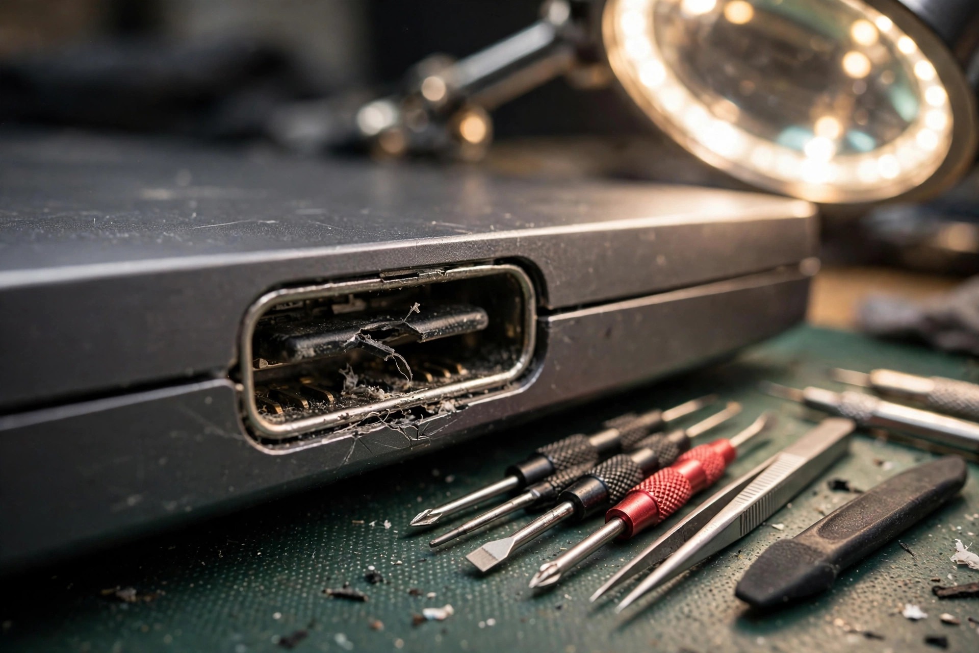
A plug that only charges when held at an angle, a port that works upside down but not the right way up, charging that works while an external display stays black, and a large file transfer that drops halfway through are easy to misread as an adapter fault, a cable fault, a driver fault, or even a board fault. This guide stays on one layer only: the physical layer of the laptop USB-C receptacle itself. That layer is a mechanical and electrical chain made from the shell, the tongue, the contact plating, the anchor feet, the board pads, and the traces. A fault in any link of that chain can show up at the far end as no charging, intermittent charging, slow charging, a speed drop, or no picture. This batch focuses on the physical layer. Power Delivery negotiation is covered only at the boundary, not as a general protocol survey. The round DC jack is covered only as a comparison boundary, not as a repeat of the previous batch. Everything in this guide for the reader is limited to external observation and non-disassembly checks. Any work that opens the base cover, measures internal signals, desolders, replaces a receptacle, rebuilds a pad, or runs a jumper wire belongs to professional inspection. Do not attempt it yourself. If a port shows heating, sparks, a burnt smell, melted plastic, or burn marks, stop using that port at once, do not keep testing it by repeated insertion, and do not keep charging through it at high power.
1. Anatomy of a receptacle: five layers, and each layer means a different repair
A laptop USB-C receptacle is not a single piece of metal. Conceptually it can be separated into five layers. Which layer has failed determines both the symptom and how difficult the repair will be. A blanket statement that the port is broken says nothing about the repair scope.
| Layer | Structure | Common presentation when it fails |
|---|---|---|
| Shell and chassis opening | A stainless steel shell around the receptacle, held by the chassis frame and the board | A deformed shell or a widened opening, a plug that wobbles, a plug that cannot hold its seating depth |
| Tongue and mid-plate | A thin central tongue carrying one row of contacts on each face; a mid-plate reaching into the tongue corners, separating the two rows, providing ground shielding, and blocking non-Type-C plugs | A chipped, cracked, or bent tongue, one row of contacts losing support, a single-direction or single-function failure |
| Contacts and plating | Copper-alloy spring contacts, nickel underplating with a gold finish; 24 pins in total in two rows | Worn-through plating, oxidation, rising contact resistance, intermittent behaviour, angle dependence, a need to press the plug to get a response |
| Anchor and retention feet | Feet that carry mechanical load from the receptacle into the board, in surface-mount, through-hole, or hybrid forms | The whole receptacle moving relative to the chassis, all functions dropping together when the plug is moved |
| Solder feet, pads, and traces | Contact tails soldered to board pads, then routed onward to later circuits | Cracked solder, lifted pads, broken traces; replacing the receptacle alone may not fix the fault, and board-level work may be needed |
2. Why normal insertion still wears a port out: friction, plating wear, and retention loss
Under the USB-IF system, the durability baseline for a USB-C connector is 10,000 mating cycles. That figure appears consistently in specification summaries from Amphenol, Molex, and JAE, and it is not a marketing figure from one maker alone. Three qualifications must travel with that number. First, 10,000 cycles is a minimum durability requirement under standard test conditions, not a promise that cycle 10,001 will fail. Second, the test is axial mating. Real-world angled insertion, sideways load, and mating with dust in the port will all shorten real life below the test value. Third, the detailed test conditions for each maker must be taken from that maker's full specification. Public summaries do not list the full test conditions, and this guide does not invent test speeds or test angles to fill the gap.
| Item | Amphenol summary | Molex summary | JAE DX07 summary |
|---|---|---|---|
| Durability | 10,000 cycles | 10,000 cycles | 10,000 cycles |
| Insertion force | 5 to 20 N | 5 to 20 N | The same set of figures is not listed in this batch summary |
| Extraction force | 8 to 20 N, falling to 6 to 20 N after durability testing | 8 to 20 N, falling to 6 to 20 N after durability testing | The same set of figures is not listed in this batch summary |
| Contact resistance | The same set of figures is not listed in this batch summary | Initial limit 40 mOhm, limit after testing 50 mOhm | Initial limit 40 mOhm |
| Plating and materials | High-temperature polymer housing, copper-alloy contacts, stainless steel shell | Plug contact gold minimum 0.76 um, receptacle contact gold minimum 0.025 um | The same set of figures is not listed in this batch summary |
3. Why a tongue breaks, cracks, or wears away: thin plastic plus leverage plus fatigue
On tongue material, Molex describes a high-temperature nylon insert-moulded receptacle housing, formed in three insert-moulding steps into a single piece, with the stated aims of reducing water ingress and preventing terminal lift. Amphenol lists a high-temperature polymer housing, copper-alloy contacts, and a stainless steel shell. Those choices already state the design trade-off. A tongue must be thin enough to fit two rows of 24 pins, stiff enough to support a plug, and tough enough not to snap under a prying force. No single plastic maximises all three at once. High-temperature nylon and engineering plastics are strong on reflow temperature tolerance and dimensional stability, and weak at fatigue in a thin-walled root under repeated bending.
The failure path, in order of loading and stated as a mechanism inference, runs as follows. First, angled or misaligned mating: a plug pushed in before it is aligned puts sideways shear on the tongue tip, scratching the surface and chipping the corners. Second, leverage: when a laptop is moved with a cable attached, when a cable is pulled, or when a laptop falls, the plug becomes a lever and the pivot is the tongue root and the receptacle opening. Lever torque equals force multiplied by lever arm, so a longer cable and a longer exposed plug section put more force on the root. Third, fatigue cracking: every prying movement is one small bend. Plastic at the root bends repeatedly, a crack starts as a fine surface crack and grows inward. Early on, the visible sign may be only a thin line, while contact support is already loosening. Fourth, breakage or a missing corner: once a crack reaches a critical size, one larger prying force breaks the tongue. A broken fragment can jam a contact or leave one row of contacts without support so that the row sags. Fifth, contact sag or displacement: without tongue support, a spring contact no longer keeps its design height and normal force, and contact becomes point contact or on-off contact.
Wear and breakage must be separated. Wear is gradual, with symptoms moving from an occasional drop to frequent drops. Breakage or impact damage is sudden, with symptoms appearing right after a drop or a cable pull. Asking when the fault started and whether the laptop was dropped or the cable pulled is therefore not small talk. It is the key boundary between fatigue and impact damage. A further danger extension, stated as an inference to be confirmed by inspection, is that a broken fragment or a deformed contact can let neighbouring pins touch each other. If an abnormal conduction path appears between VBUS and GND or CC pins, later protection circuits may operate, and later components may be damaged. For that reason, if a tongue shows visible damage, do not keep inserting and removing a plug to see whether it still works. Stop using that port and arrange inspection. That is a safety instruction, not a claim that every tongue injury causes a short circuit.
4. Why anchors and solder feet loosen: the load path decides where failure starts
Receptacle fixing falls into three forms, each with a different mechanical weak point, stated as a mechanism inference against maker structural descriptions.
| Fixing form | Structure | Mechanical weak point (inference) | Typical symptom |
|---|---|---|---|
| Pure surface-mount | Signal feet and shell solder feet all sit on the board surface, held by solder and pad adhesion | A sideways pull becomes a peel force, and solder resists peeling far less well than shear; repeated prying fatigues the solder until it cracks | The whole port rocks, contact only when pressed, a shake breaks the connection |
| Through-hole retention post | Fixing feet pass through board holes, giving deeper mechanical engagement | One strong pull can still tear copper or pads around the hole, but the fatigue threshold is higher than for surface-mount | After a strong impact the whole receptacle shifts and the chassis opening no longer lines up |
| Hybrid | Signal feet surface-mount, fixing feet through-hole or larger solder feet carrying mechanical load | The design intent is that fixing feet carry mechanical load and signal feet carry signals; but if a fixing foot is already loose, load transfers back to the signal feet | Looseness at first, then intermittent signals later |
5. The 24-pin map: why one function can die while the others stay alive
The 24-pin grouping for a receptacle is established. The core diagnostic logic is that the 24 pins do not live and die together. Which pin group fails first depends on where that group sits on the tongue, how worn it is, and how corroded it is. A symptom such as charging works but data does not, or data works but picture does not, is therefore very likely a local physical-layer failure, and should not be blamed at once on drivers or protocol.
| Pin group | Pins | Function | Typical presentation when physically damaged (inference, matched to pin-group function) |
|---|---|---|---|
| GND | A1, A12, B1, B12, 4 pins in total | Ground return | One poor GND pin may not cut the connection at once, because the remaining GND pins can share current; but if the whole GND return degrades, both signals and charging become unstable |
| VBUS | A4, A9, B4, B9, 4 pins in total | Positive power | One failed pin may still allow low-current charging, but high-current charging heats up or drops out; only multiple failed pins produce a complete loss of charging |
| CC | A5 (CC1), B5 (CC2), 2 pins in total | Direction detection, role detection, Power Delivery communication carrier | The most important boundary pin group, covered in section 6 |
| D+ and D- | A6, A7, B6, B7, a USB 2.0 differential pair shorted inside the receptacle into one pair | USB 2.0 data | Charging normal but a USB 2.0 device not recognised, a mouse or keyboard dropping intermittently |
| TX and RX | A2, A3, B11, B10 and related pins, 8 pins in total in two transmit and receive differential pairs | SuperSpeed and USB4 high-speed data, display alternate mode | A high-speed device slowing down, a display flickering or showing no picture, while charging and USB 2.0 may stay normal |
| SBU | A8 (SBU1), B8 (SBU2) | Alternate-mode sideband signals | Display alternate-mode faults, while charging and ordinary USB data may stay normal |
6. The CC boundary with Power Delivery: direction-related failure points to the physical layer first
The CC mechanism points are established. When a plug is inserted, only one of the two rows of CC pins mates with the plug: CC1 for one orientation and CC2 for the reverse orientation. The source side judges direction by which pin sees the sink pull-down resistance of about 5.1 kOhm. Power Delivery communication also travels on the same CC line. Because only one CC pin is used at a time, CC physical failure has a highly characteristic symptom, stated as an inference from that mechanism. Single-direction failure, where one orientation charges normally and the reverse orientation does not charge at all, or the reverse pattern, most likely means one side CC pin has poor contact, corrosion, or a cracked solder foot, rather than a protocol fault, because a protocol layer has no reason to accept only one orientation. Failure in both directions with a second port working normally points to both CC sides of that receptacle failing, or to a VBUS and GND layer fault, or to the whole receptacle coming loose, and it still belongs to physical-layer suspicion first. Only when two ports, two cables, and two adapters show the same presentation should suspicion move toward the adapter, the cable, the system protocol, or the charging controller layer. The boundary rule can be stated plainly: direction-related failure means CC physical layer first; direction-independent failure across multiple ports means exclude cables and adapters first, then suspect the protocol or controller layer. This batch does not expand into Power Delivery message formats, voltage-step negotiation flow, or negotiation timing. That material belongs to the Power Delivery guide.
Two further CC points deserve emphasis. CC pins are fine, and they sit near the centre of the tongue, so corrosion, dust, and tongue deformation affect them proportionally more than the larger VBUS and GND pins. By inference, light corrosion may show up first on a CC pin, while the high-current VBUS path fails later. Intermittent failure to recognise an adapter can therefore be an early physical-layer warning, not something to ignore until charging stops completely. On the boundary between the physical layer and the protocol, CC duties split into three stages: attach detection, direction detection, and Power Delivery message carriage. A source pulls CC up with Rp, a sink pulls CC down with Rd, and the source treats the link as connected and outputs VBUS only after it detects Rd. Before Rd is detected, VBUS stays in principle at 0 V, the so-called cold socket. A broken CC pin, oxidation that pushes contact resistance too high, or a deformed tongue that stops a CC pin touching can therefore produce a state where a cable is inserted but treated as not inserted: an adapter light may look normal, yet the laptop shows no charging response at all, not even initial power. A controller-side point supports the same boundary only: one class of USB Type-C controller separates the Power Delivery controller, the cable-plug and direction-detection circuits, and the power-path switches, with Power Delivery data leaving on one CC line or the other depending on cable direction, and hardware design guidance states that CC lines should run directly to the receptacle without passive parts between the controller and the receptacle. In other words, physical damage to a CC pin or CC trace can defeat detection before the controller ever sees a signal. Inspection therefore cannot check the controller alone. Pins and traces must be checked first.
7. The remaining pin layers: VBUS, GND, D+, D-, high-speed pins, and SBU
VBUS and GND each have 4 pins, giving parallel redundancy by design. When one VBUS pin makes poor contact, a low-power state such as idle or low-current charging may still pass. At high-current charging or when an attached device draws more current, the remaining pins must carry all the current, contact heating rises, thermal expansion and contraction worsen micro-movement, and the result is a load-related intermittent fault that looks normal at low current and drops out, slows down, or heats up at high current. GND failure follows the same logic: loop resistance rises and the signal reference point drifts, with high-speed signals especially sensitive. The repair meaning is that discolouration, burn marks, or a single collapsed pin on VBUS or GND must not be treated as mere dirt. The current path has already narrowed, and continued high-power charging may widen the damage. Burn marks, melting, abnormal heating, or a burnt smell mean the port must be stopped at once, without repeated insertion tests.
D+ and D- carry USB 2.0 data. When the high-speed pins have all failed but D+ and D- still work, the system may fall back to USB 2.0 mode: a device is still recognised and files still transfer, but speed falls to USB 2.0 level. A user experiences this as slower, but the mechanism is a fallback after high-speed channel failure, not a slow cable. In the reverse case, D+ and D- failure with healthy high-speed pins can still produce charging normal with a high-speed device not recognised or dropping intermittently, because enumeration and some control signals still depend on the USB 2.0 path. Charging and data must therefore be tested separately. Charging success does not prove the port is healthy.
Need a laptop repair expert?
Free diagnosis · Transparent pricing · No fix, no fee · 180-day warranty
Four high-speed differential pairs carry USB 3 and USB4 high-speed data, and in alternate mode they can be reassigned as the main link for display signals. The layered consequences are: one failed high-speed pair drops a dual channel to a single channel, halving bandwidth or lowering speed, so an external display may fall from a high resolution or high refresh rate to a lower mode, or flicker and drop out under high-bandwidth demand. Multiple failed high-speed pairs drop high-speed transfer completely back to USB 2.0, or remove an external picture completely, while charging through CC plus VBUS can stay fully normal. Poor high-speed contact short of a complete break degrades signal integrity first, showing up as a large file transfer dropping midway, a high-speed external drive disappearing intermittently, or an external display failing only at a particular resolution. That load or bandwidth pattern is an important clue for high-speed physical-layer trouble, and it differs from the insert-and-dead pattern of CC failure. The key boundary is that a high-speed pin fault does not stop charging completely. If charging has also stopped completely, the fault is not in the high-speed pins alone. The search must move upward to CC, VBUS, or the controller layer.
SBU1 and SBU2 are low-frequency sideband pins, and they do not carry main picture pixels themselves. In DisplayPort alternate mode, SBU carries the auxiliary channel: display identity and capability information and the two-way control messages needed for link training, while main picture data travels on the reassigned high-speed channels. In USB4, SBU becomes a sideband channel for protocol management. SBU failure therefore has a highly characteristic and easily misread presentation: charging normal and USB devices normal, but an external display completely blank or not recognised, because the auxiliary handshake has failed, the display identity never arrives, the system never learns what display is attached, and so it never outputs main picture data. An external display that works intermittently, succeeding only after several insertions, points to SBU contact resistance at a critical value, where identity and link training succeed sometimes and fail other times, and a failed training run means no picture for the whole session. A common misunderstanding must be corrected: SBU failure does not mean the cable has no bandwidth. Conversely, a high-speed pin fault does not let SBU auxiliary messages compensate. The two pin groups divide the work: SBU negotiates the handshake, and high-speed pins deliver the picture. If the handshake never completes, a healthy picture channel is useless.
8. Damp corrosion: from one thin water film to intermittent disconnection
Hong Kong Observatory climatological normals for 1991 to 2020 give a yearly mean relative humidity of 78 percent and yearly rainfall of 2,431.2 mm. Monthly normals for 1971 to 2000 give monthly mean relative humidity of 81 to 84 percent from April to August. A laptop port therefore lives long-term in a humid background, not only in rain. Maker environmental test figures give a useful contrast: Amphenol lists a humidity test at 40 plus or minus 2 degrees Celsius, 90 to 95 percent relative humidity, for 96 hours, a temperature life test at 105 plus or minus 2 degrees Celsius for 120 hours, and a working temperature range from minus 40 degrees Celsius to plus 85 degrees Celsius. Those figures show that a connector is designed with humid exposure in mind, but the humidity test lasts only 96 hours. It is not a promise of unlimited high-humidity survival. Hong Kong inputs to the same mechanism include condensation inside a port when a laptop moves between an air-conditioned room and hot outdoor air, damp air trapped in a backpack during commuting, rain splash, hand sweat, and spilled drinks, where soft drinks, coffee, and tea all leave electrolyte and acidic or sugary residues, plus salt carried in from coastal air or from hands. Humidity must not be overstated: it is one necessary condition, not a sufficient condition. Corrosion speed is set by a water film plus an electrolyte plus a voltage difference plus time, all present together.
The five-step chain from reversible to irreversible, stated as a mechanism inference against plating structure and industrial material, runs as follows. Step one is water-film formation. A USB-C receptacle is not a waterproof design. It is a precise deep cavity opening, and water, dust, and pollutants can sit at the bottom of the cavity. Condensed humid air, sweat, and drink residue can form a thin water film on pin surfaces that may not be visible to the eye. Pure water itself conducts poorly, but once salts dissolve into it, the film becomes an electrolyte carrier. Step two is plating wear and pore exposure. Normal mating wear, dust scratching, and sideways-force scratching thin the plating or open pores, exposing lower metal layers. Step three is electrochemical corrosion. In an electrolyte water film, neighbouring pins sit at different potentials, the anode metal oxidises and loses material, and the cathode reduces and deposits metal. A liquid-corrosion application note states this clearly: copper is a common contact material, anode copper oxidation loses dimension, and cathode deposition can grow in a dendrite form that can finally short neighbouring pins. Pin spacing is only about 0.5 mm, so the distance a dendrite or a corrosion deposit must cross is very short, which is why a high-density port is especially vulnerable to liquid. Step four is corrosion product and rising contact resistance. Copper first oxidises to copper oxide, dark brown or black, then converts under water, carbon dioxide, sulphide, and chloride action into basic copper carbonate, basic copper sulphate, and basic copper chloride products in green or blue-green colours, the green rust seen by eye. Colour is not the key point. Conductivity is. Corrosion products conduct far worse than metal, so contact resistance rises. On signal paths, CC detection voltage drifts, SBU auxiliary signals weaken, and high-speed differential signal integrity degrades, first as intermittent faults rather than an immediate total break. On power paths, higher VBUS resistance means more heating at the same current, thermal expansion worsens micro-movement, micro-movement scrapes away more plating, and a vicious circle forms. Step five moves from intermittent disconnection to a short circuit or a total break. Corrosion deposits build up, dendrites grow, or pins thin and break from material loss, ending in one of three outcomes: one pin breaks completely, so its function fails permanently; neighbouring pins leak or short, for example VBUS shorting to CC or SBU, so later controller and protection circuits face voltages beyond design and damage spreads from the port to the board; or the receptacle body jams with corrosion product so a plug cannot seat fully, which looks like looseness but is actually blockage.
Fretting corrosion is a second line. Even without an obvious liquid event, daily small movements of a port, from cable weight pulling a plug, typing vibration, and backpack movement, cause micrometre-scale relative sliding at the contact point, called fretting. Industrial material states that fretting corrosion is slow mechanical wear at a contact face caused by micro-movement, accelerated by heat and humidity, showing up as contact resistance rising gradually over months. The Hong Kong amplifier is that high humidity oxidises freshly exposed metal from fretting faster, and the next fretting movement scrapes that oxide away again, in a scrape, oxidise, scrape-again cycle, so contact resistance does not rise in a straight line but jumps intermittently: a sudden drop one day, recovery after a nudge, and another drop days later. Dampness is therefore not a lone cause. It is an amplifier. Wear thins plating, dampness oxidises the exposed underlayer faster, oxidation worsens contact, the user presses and shakes the plug harder, and shaking accelerates wear and solder fatigue. That vicious circle must be stated, not written as two independent causes.
| Appearance | More likely mechanism | Conclusion that must not be drawn at once |
|---|---|---|
| Light green or blue-green powder or crystals on pins | Copper corrosion products, including carbonate, sulphate, and chloride forms | Colour alone cannot identify which salt, nor how deep the corrosion runs; check whether pins have thinned or broken |
| Dark brown or black pins | Copper oxide or sulphide film | Not necessarily deep corrosion, but contact resistance may already have risen |
| Bright pins with poor contact | Plating wear, tongue deformation, cracked solder, dust isolation | A clean look does not mean normal contact; judge by the function matrix and by mating feel |
| White crystals or sticky residue inside a port | Sugar or salt residue left after a drink dries | Residue itself can absorb moisture and keep acting as an electrolyte; after cleaning, function must still be rechecked, and appearance alone cannot close the case |
9. One overload versus long fatigue: the timeline itself is evidence
A single overload includes a dropped laptop, a pulled cable, a stepped-on cable, and a hard object pressing a plug inside a backpack. Its mechanical signature is a sudden high torque, and its failure modes are mostly tongue breakage, shell deformation, immediate anchor solder cracking, and pad tearing, with sudden symptoms and a clear time point. Long fatigue includes repeated daily mating, moving a laptop while a cable stays attached, and sustained light sideways pressure from backpack squeezing. Its mechanical signature is low-amplitude repeated stress, and its failure modes are mostly plating wear, retention loss, solder fatigue cracks, and fine tongue-root cracks, with gradual symptoms and a vague time point. The repair meaning differs. A single overload needs a check for hidden damage, for example a shell that looks intact while a pad has already torn halfway. Long fatigue needs a check of the whole port system, because the tongue, contacts, and anchors may have aged together, and replacing one part alone may not cure the fault.
Hong Kong commuting provides the most direct local example, stated as an inference. Getting on and off trains and buses with a cable snagged, a laptop shaking while walking, and a zip forced over a full backpack pressing a plug are all leverage sources. The point is not one very strong pull, but several small prying movements repeated every day, with fatigue accumulating as the main cause. If a charging cable stays attached inside a backpack, backpack squeezing applies sideways force to the port for a long period. The force is not large, but its direction stays fixed, so one side anchor and solder foot take a disproportionate share. Prevention follows the mechanism, without being stated as a guarantee: remove the cable before packing the laptop away; use a short cable or a right-angle cable to shorten the lever arm, while noting that a right-angle cable is not a cure by itself, because a poorly made right-angle plug with poor tolerances can increase angled-mating risk, so plug workmanship and retention matter more than shape alone; keep hard objects in a backpack from pressing directly on one side of a port; keep a port dry, and do not leave a cable attached and unmoved for a long time in a damp environment; check periodically for green or white corrosion material or dust build-up; and never scrape a tongue hard with a metal object when corrosion material is found.
10. Layered exclusion: from outside to inside, without skipping levels
The flow principle is that each level excludes only that level, and changing everything at once is not a substitute for diagnosis. Every step must record which direction, which port, and which function produced the result, or the next step cannot draw a boundary. A safety gate applies before any step: if burn marks, melting, deformation, abnormal heating, a burnt smell, or liquid inside a port is seen, stop using that port at once, do not test by repeated insertion, and do not charge at high power. The flow below assumes no such danger sign is present.
| Level | Reader check | Reading |
|---|---|---|
| Level 0, visual and feel, without power | Look for a chipped, cracked, deformed, or sideways tongue; blackened contacts, green or white corrosion material, or dust build-up; a deformed shell or widened opening; shake a plug gently, without strong prying | If a tongue is already broken or visibly damaged, stop using that port, skip to level 5 inspection, and do not test by repeated insertion; movement of the whole receptacle points to anchors or solder, while looseness of the plug inside the port alone points to retention or tongue |
| Level 1, cable and plug | Change to a known-good cable and a known-good adapter or device, and test both insertion directions on the same port | If a cable change fixes the fault, the fault sits on the cable plug side; if two cables give the same presentation, the fault stays on the laptop side, and the flow moves to level 2 |
| Level 2, direction and port comparison | Test the same cable in both directions and record which direction fails; on a laptop with a second USB-C port, test the second port as well | Single-direction failure points to that side CC pin or that side contact layer first; failure in both directions with a normal second port points to that receptacle as a whole first; the same fault on both ports moves the flow to level 4 |
| Level 3, function-group comparison | Test charging, a USB 2.0 device such as a mouse, a high-speed device or external drive, and display output separately, where the model supports display output | Charging normal but USB 2.0 not recognised points to D+ and D- first; charging plus USB 2.0 normal but high-speed or display abnormal points to TX, RX, and SBU first; intermittent charging with normal data points to VBUS, GND, and CC first; if the model never connected a pin group, missing display output may be a model limit, not a fault |
| Level 4, shared-cause exclusion | After excluding adapter, cable, and device shared causes, if both ports, both directions, and all functions show the same presentation, only then move suspicion toward power, protocol, and charging-controller layers | This level does not expand into Power Delivery protocol analysis or controller measurement steps; it only draws the boundary conclusion |
| Level 5, disassembly inspection, professional scope only | Check anchor solder feet for cracks, pads for lifting, traces for breaks, tongue roots for cracks, and neighbouring parts for load damage | Readings split into three grades: receptacle grade, pad grade, and board grade; difficulty and risk rise grade by grade, and quoted cost and handling time differ too, so they must be stated separately and never collapsed into one phrase such as replace the port |
11. Misdiagnosis traps: similar symptoms, completely different mechanisms
| Misdiagnosis | Why it is wrong | Correct boundary |
|---|---|---|
| Calling an adapter faulty at the first sign of no charging | No direction and port comparison has been done, and single-side CC physical failure can look like an adapter fault | Do levels 1 to 2 first: change cable, change port, compare both directions |
| Reinstalling drivers or updating the system at the first sign of intermittent disconnection | A driver problem does not usually recover when a plug is shaken; shake-related symptoms point to retention or solder layers | Look at the link between symptom and movement: tied to shaking, angle, or direction means physical layer first |
| Treating successful charging as proof that a port is healthy | VBUS and GND use parallel pins, so one failed pin can be masked by the others sharing current; CC and data pins may already have failed | Test charging, USB 2.0, high-speed transfer, and display output as four separate boxes |
| Calling one-direction failure an unstable protocol | A protocol layer has no reason to accept only one direction; a single-direction symptom fits single-side CC physical failure best | Follow section 6: single direction means CC physical layer first |
| Excluding the physical layer because a tongue looks intact | Fine tongue-root cracks, solder fatigue cracks, and worn-through plating may not be visible; retention loss is not visible either | A normal look does not mean a normal physical layer; combine direction, function, and shake tests before excluding it |
| Treating all USB-C ports as soldered, or all as modular | Dell and Lenovo have modular models, while Dell XPS and HP EliteBook have soldered models; even one brand is not uniform | Check the service manual for the exact model, and do not infer structure from brand |
| Pressing a loose port hard, packing it with paper, or prying contacts | Force spreads tongue cracks and can turn a partial pad tear into a full tear; foreign material can short pins or deform the port further | Looseness is a symptom, not a reason to apply more force to clamp it; stop using the port and arrange inspection |
| Treating a DC jack fault as a USB-C fault, or the reverse | The two power paths differ; the previous batch already covers the DC jack, and symptoms can overlap as no charging in both cases | Compare power ports: DC charging normal with USB-C charging failed points to the USB-C path, and the reverse pattern points the other way; both ports failing points to a shared cause first |
| Treating a Power Delivery protocol problem as a broken port, or the reverse | Protocol problems usually show the same fault across ports and cables; physical problems usually stay with one port, one direction, or one function | Use levels 2 and 4 to draw the boundary, and do not settle the case on one test |
| Changing a cable without success and concluding that the board must be faulty | A cable change excludes only the cable; it cannot exclude a CC pin, an anchor, a controller, a protection part, or an adapter output step | Test two known-good cables, both directions, a second known-good adapter, and a second port, recording each box |
| Treating a fault that returns days after cleaning as already solved | Cleaning removes only dust and surface residue; it cannot restore lost metal, a broken tongue, or a cracked solder joint; a corrosion layer scraped open may conduct briefly, then oxidise again, so recurrence is expected | After cleaning, recheck both directions, high load, and continuous use; recurrence means physical damage remains, and cleaning must not be repeated without limit |
| Treating a plug that cannot enter or cannot seat as simple looseness | Failure to enter can mean dust or corrosion product blocking the cavity bottom, or a bent tongue blocking the plug; failure to seat can mean retention wear; the two causes are opposite, and the handling is opposite | Inspect with power off under good light; never dig with a metal object, and never force a plug in |
| Assuming a drop or cable pull can only damage the outside | Drop and pull leverage acts directly on port anchors and the tongue: the shell may show no mark while an anchor solder foot has already cracked and a tongue has already bent; a clean outside does not mean a clean inside | Use the receptacle-body movement test plus a function matrix comparing before and after the impact; if in doubt, do not continue high-power use |
| Treating a drink spill that was wiped dry as harmless | Sugar and salt residue left after drying can still absorb moisture and keep acting as an electrolyte; corrosion can show up as an intermittent fault days or weeks later | Record the liquid event and its timing; a later intermittent fault must be considered with that history, not as an unrelated new fault |
| Treating a working second port or dock as a reason to ignore the original port | Switching to a second port is a valid bridging plan, but if the original port has a short circuit, burn damage, or corrosion product, testing it again by inserting a cable still carries risk; a bridging plan requires the original port to be stopped, with no heating, smell, or burn damage | After stopping the original port, still check for heating, smell, and burn marks; if any doubt remains, do not test it again under power |
| Assuming that all USB ports failing together must mean one port is faulty | Simultaneous failure across ports points to a shared power rail, a controller, driver or firmware, or a shared board path; one physical port injury cannot explain simultaneous multi-port failure | Compare USB-C, USB-A, and DC charging paths for simultaneous failure |
| Assuming that one faulty USB-C port must mean only the port body is faulty, so replacement must fix it | A single-port fault can still sit in that port dedicated controller, high-speed multiplexer, or protection part, not in the port body; replacing the body may then change nothing | Before disassembly, use the function matrix to locate the fault to the port body or to the circuit behind the port |
12. Modular versus soldered: speak by model, never by brand alone
Do not write that all laptop USB-C ports are soldered to the board, and do not write that all can be replaced as modules. Reality splits by model into two broad classes: one class is soldered to the board, where the maker official repair path is board replacement; the other class is modular, with a small board or slot module fixed by screws, which can be replaced alone. Only the service manual for the exact model can settle the case. Structural comparison examples are comparisons only, and they do not mean other models are the same: Dell Pro16 Plus PB16255 and Dell Pro13 Premium PA13250 both have an independent USB Type-C module, fixed by screws to the board or to the left input and output board, and removable for replacement; Lenovo ThinkPad T14 Gen 7 has two modular USB-C ports, fixed by a bracket and screws, and slidable out for replacement; Dell XPS 13 9300 has both USB-C ports soldered to the board; HP EliteBook 850 G8 has both USB-C ports soldered to the board, with the maker official repair path as board replacement, while the same machine left-side USB-A charging port has an independently replaceable small board, and the two must not be confused. Lenovo also has models with an independent USB 3.1 Gen 1 Type-C connector small board, connected to the board by a flexible cable, replaceable alone. On parts reality, a USB-C receptacle part number varies by model, pin count, and mounting form, and no single receptacle fits all laptops. A modular model makes module replacement relatively direct. A soldered model needs board soldering, and pad tearing must be checked first. Local stock and whether a part number matches the maker specification can only be confirmed after inspection matched to the model. This guide makes no promise of immediate stock replacement. A pre-inspection reminder is useful: before sending a laptop in, record which port, which direction, which function failed, and after which impact it started. Those four facts decide the starting point of layered exclusion and can save repeated testing.
13. Repair, replacement, and upgrade decisions: split by damage grade, not by symptom severity
Decisions must split by damage grade, not by how severe a symptom looks, because one symptom such as no charging can hide three completely different repairs. The decision order is: first judge which layer the damage stops at, then judge whether repair can restore the design contact pressure and insulation spacing, and only then judge whether repair is worthwhile. All three judgements are required. Skipping the second judgement, for example replacing a visually similar receptacle while pads have already lifted, is a main cause of recurrence.
| Case | Conditions | Direction and recheck |
|---|---|---|
| Case A: cable or plug layer | Level 1 has already excluded the fault to outside the laptop | Replace the cable or plug side; the laptop receptacle needs no work; choose a cable with good plug workmanship and normal retention; avoid long-term angled mating, and avoid continuing to wear the receptacle with an already loose plug |
| Case B: receptacle layer, tongue, contact, or anchor damage, pads intact | The function matrix maps fully to the port body, for example single-side CC failure, tongue deformation, or retention loss, while other ports and charging paths stay normal; disassembly inspection confirms anchor pads intact, traces unbroken, no corrosion spread on the board, and no burn damage | A modular model replaces the independent module or small board, a relatively direct path; a soldered model replaces the receptacle by soldering, with the part number matched to the original machine; recheck the function matrix four boxes in both directions; cost is subject to a written quotation after inspection; do not continue using a port with a broken tongue, and do not force a receptacle out yourself |
| Case C: pad or trace layer | Pads lifted, traces broken, or board cracks; a break can be traced to a clear start and end point, a trace can be rebuilt reliably, and rebuilding will not seriously unbalance high-speed differential trace length or symmetry | Board-level work, including pad rebuilding, jumper-wire repair, or trace repair, at higher difficulty and risk than case B; if the damage range is large, the owner must be told clearly about post-repair reliability and later risk, not only told that repair is possible; high-speed traces are especially sensitive, and an overlong jumper may prevent high-speed functions from returning to original speed, which must be explained in advance; recheck the function matrix four boxes in both directions, with the high-speed box noting specifically whether speed has returned |
| Case D: multi-port or multi-function shared cause | The physical layer has already been excluded and the fault points to the protocol or controller layer; or a new receptacle body still fails, or a VBUS short to CC or SBU has caused linked damage, or burn damage sits around a controller or protection part | Hand the case to the Power Delivery or charging-controller scope; do not keep replacing receptacles at the physical layer, because replacement cannot fix a shared-cause fault; after board-level repair, the full function matrix must be rechecked, and no box may be skipped to close the case; if any box stays unstable in recheck, the repair must be treated as incomplete, not as usable for now |
| Case E: preventive upgrade, port not yet broken but in a high-risk use pattern | Daily repeated mating, long-term commuting with a laptop, or long-term use with a cable attached | Remove the cable before packing, reduce angled mating, keep the port clean and dry, and arrange inspection early when a single-direction or intermittent symptom appears; early CC or plating trouble usually carries lower handling cost and risk than waiting until pads tear, stated as a mechanism inference, not as a cost promise; never promise that replacement makes a port unbreakable forever, because the 10,000-cycle durability baseline itself shows that a port is a consumable mechanical part |
| Bridging plan: switch to another port or dock | The laptop still has another fully normal USB-C port or DC charging port, verified as fully normal by the function matrix; the damaged original port has been stopped, with no heating, smell, burn damage, or liquid residue; charging power and external display needs during the bridging period can be covered by the healthy port | A dock itself must connect to the healthy port, and must never connect to a suspected short-circuit port; switching to another port bypasses the damaged point, it does not repair it; short-circuit or corrosion risk in the original port does not disappear automatically because it is unused; if the original port shows burn damage, heating, or smell, inspection must still be arranged even after switching, and the port must not be left ignored long-term |
| Replacement-machine consideration | Multiple ports failing together, board delamination or burn-through, large-area corrosion spread, or board-level repair still failing the full function matrix; other laptop parts also near end of life, lowering the overall value of a single-port repair | This judgement must rest on whole-machine inspection results, not on the port alone; the replacement decision rests on a written quotation after inspection, and this guide sets no money threshold |
14. Worked scenarios: four hypothetical examples using layered exclusion
The four scenarios below are purely teaching scenarios, not real cases. Their purpose is to show how layered exclusion works. Do not treat any scenario as a diagnosis for your own laptop. No real names, real cases, or reviews appear here.
Scenario one, purely a teaching scenario: a user carries a laptop daily, keeps a charging cable attached, and keeps a water bottle in the same backpack. After three months, the laptop charges only in the reverse orientation, and drops in and out in the normal orientation. By the section 6 boundary, that single-direction symptom raises suspicion first for one side CC contact layer, not for an adapter change at once. Layered exclusion starts with a cable comparison, then a direction comparison, and only after the single-direction symptom reproduces steadily does it point to the physical layer of the port.
Scenario two, purely a teaching scenario: a user closes a laptop lid without removing a cable, backpack pressure presses the plug against the tongue root, and after six months the port starts to rock, charging only when shaken. That pattern raises suspicion first for anchor or solder fatigue, not for a protocol fault. Layered exclusion must separate a plug rocking inside the port from a receptacle body rocking inside the chassis. The first points to the tongue or retention, the second points to anchor solder feet, and the two repair paths are completely different.
Scenario three, purely a teaching scenario: a laptop charges normally, but an external display shows no picture at all, while USB devices work normally. Layered exclusion tests four boxes separately: charging normal, USB 2.0 normal, display abnormal, pointing first to SBU sideband handshake failure, not at once to a faulty display or an unsupported cable. The display and the cable must still be cross-checked on a second known-good system before they can be excluded.
Scenario four, purely a teaching scenario: a laptop transfers large files at a speed that stays steadily at USB 2.0 level, while charging stays completely normal. A user may feel the cable is slow, but the mechanism may be high-speed pin failure with fallback to USB 2.0. Layered exclusion compares speed with a known-good high-speed device plus a known-good cable. If speed stays steadily at USB 2.0 level, suspicion falls on the high-speed pin layer. If charging also stops completely, the search must move upward to CC, VBUS, or the controller layer, and must not stop at the high-speed pin layer.
The shared lesson of the four scenarios is that a symptom alone is never enough for a conclusion. Comparison results are the evidence. Each comparison excludes one layer only, and one comparison result must not be inflated into a whole conclusion. A fault that returns days after cleaning does not mean the problem is solved. A full recheck is required before a case can be closed.
15. What research could not verify: stated plainly, not filled in by inference
Several gaps must be stated honestly, and inference must not be used to fill them into conclusions. First, this research round found no maker document dedicated to mechanical failure of laptop USB-C receptacles from controller makers. Controller maker documents mostly cover Power Delivery controller or protection-part electrical characteristics, not receptacle mechanical life. This guide therefore does not cite controller maker documents to support tongue, anchor, or plating figures. Second, this research round did not verify, in public summaries, an item-by-item allowable contact-resistance change table from the original USB-IF durability test. The 40 mOhm to 50 mOhm figures are Molex maker specification figures, and they must not be written as an original USB-IF rule that the post-test limit is 50 mOhm. Third, this research round found no fault-rate statistics split by laptop brand for USB-C receptacles, for example which brand or year has the highest fault rate. This guide therefore writes no brand fault ranking, and only states structural differences by checking the service manual for the model. Fourth, the 10,000-cycle figures from JAE, Amphenol, and Molex each require that maker's full specification for test-condition details. Public summaries do not list full test conditions, and this guide does not invent test speeds or test angles. Fifth, no Hong Kong local public statistics split by fault mechanism were found. This guide therefore gives no proportion such as a share caused by corrosion, and the Hong Kong background rests only on Observatory humidity figures. Sixth, contact-resistance failure thresholds, waterproof ratings, and official service-manual details for individual laptop models were not checked one by one in this research round. This guide therefore does not assert a waterproof rating for an individual model, and does not present a universal disassembly procedure for all models.
16. Reader boundary and professional inspection: what to expect
What a reader can do is record symptoms and a timeline, record angle dependence and shake amplitude, compare with another known-good cable and another known-good adapter, record normal and reverse orientation results, run a multi-port comparison, record the four boxes of charging, USB 2.0, high-speed transfer, and external display separately, check the port bottom for obvious foreign material by sight only, without inserting hard objects, and photograph burn marks or plastic deformation for inspection reference. What a reader must hand to professional inspection is opening the base cover, measuring internal voltage or continuity, desoldering a receptacle, checking pads and traces, jumper-wire repair, replacing a USB-C port, and handling burn damage or a short circuit. Do not dig a tongue with a metal object, do not fix a plug with glue or paper packing, and do not press a plug hard to keep it working. If heating, sparks, a burnt smell, or plastic deformation appears, stop using that port at once and do not keep testing it.
If questions remain about inspection arrangements or cost, see diagnostic service and pricing reference, subject in all cases to a written quotation after inspection. Shop: Room 1209, Daly Plaza, Shek Mun, Shatin, telephone +852 2186 8010, WhatsApp +852 6558 6806, opening hours 12:00 to 19:00.
Safety warning
Disassembly, desoldering a receptacle, live measurement, and jumper-wire repair all carry a risk of worsening damage or causing a short circuit. Heating, sparks, and a burnt smell at a port mean contact has already become unstable, and continued high-power supply may burn board material. Do not open a laptop yourself, measure internal signals, solder a receptacle, or fix a plug temporarily with glue or paper packing. Hand all internal work to professional inspection.
Need Professional Laptop Repair?
Laptop King has 15+ years of repair experience in Shek Mun, Sha Tin. Free diagnosis, transparent pricing, no fix no fee. 180-day warranty for your peace of mind.