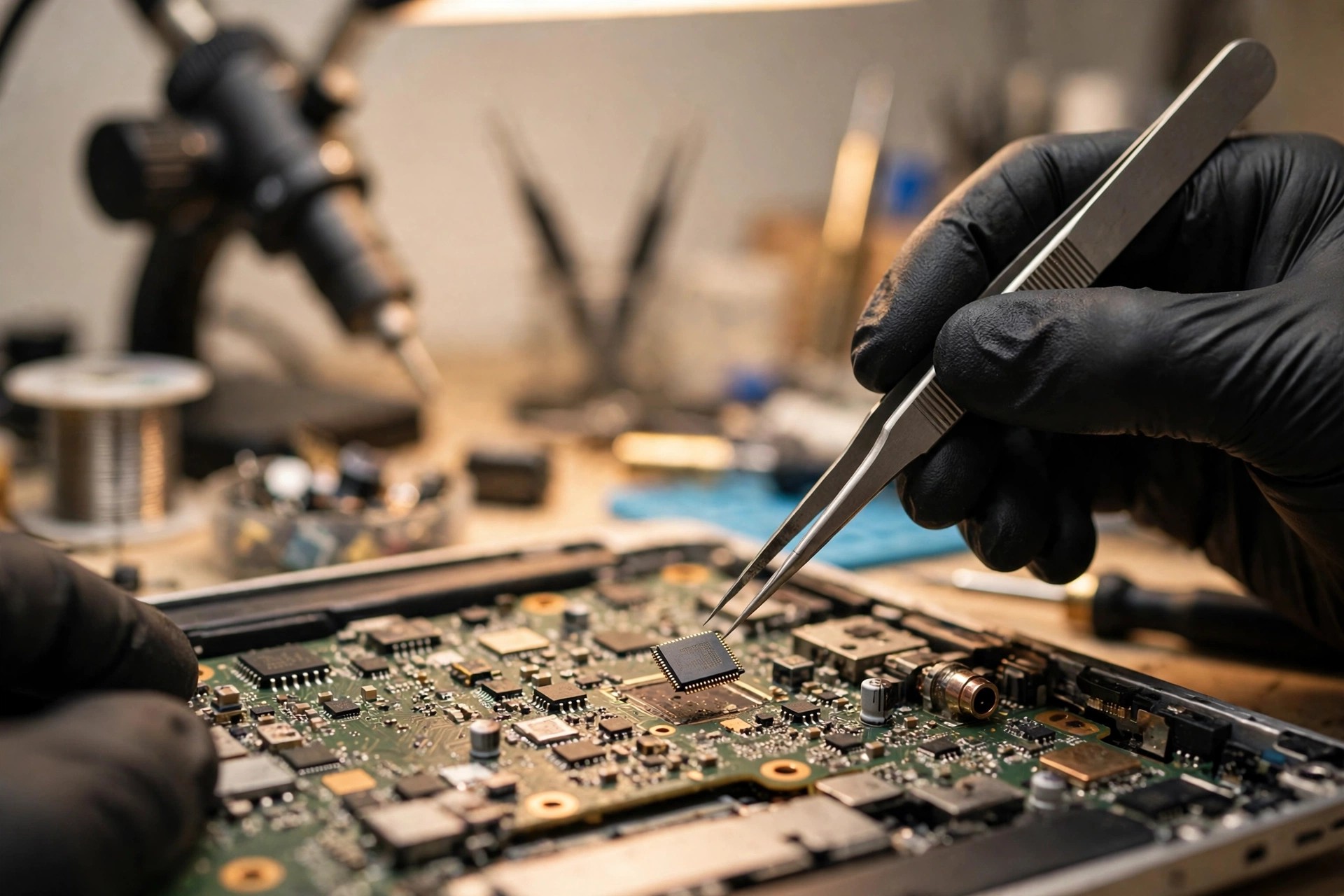
Boundary: this guide covers the codec chip and its signal chain, not the whole audio system of the machine
This guide has a deliberately narrow scope, and the scope needs to be stated at the start so that readers do not apply the wrong method to the wrong part. The main subject is the audio codec chip and the signal chain around it: the codec itself, represented by Realtek ALC series high definition audio codecs and Cirrus SoundWire codecs, the high definition audio, inter-IC sound and SoundWire bus layer, the headphone detection layer and the amplifier layer. Every symptom and every exclusion step in this guide stays inside that chain. It does not wander into other parts to explain them. The first discipline is to recognise the architecture before talking about failure. Older machines mostly use a Realtek high definition audio codec. Newer machines may use a Cirrus SoundWire codec with a separate smart amplifier, or a model that uses a USB interface instead of the traditional link. If the architecture is misidentified, the whole exclusion process will follow the wrong path, and parts will be replaced in the wrong place.
Several neighbouring subjects appear only as boundary contrasts and are not developed in this guide. The loudspeaker unit itself, including the diaphragm, voice coil and enclosure behaviour, belongs to another guide. Here the loudspeaker appears only as the end point of the chain, for example when headphone audio works but loudspeaker audio does not, which locates the fault to a branch of the output path. Physical damage to the headphone socket itself, such as a fatigued spring contact, a broken solder joint or a loose socket body, is also not the main subject here. This guide covers only the detection signal behind the socket and the way the codec interprets that signal. Mechanical socket faults are handled in the audio jack guide. Surface-level driver and setting work, such as reinstalling a driver, changing volume, switching the default device or toggling sound effects, appears only in the first exclusion layer as a way to narrow the scope. It is not rewritten as an operating manual. The embedded controller, platform controller hub, Super I/O, power sequencing and mainboard short circuit subjects appear only to the extent that the controller is the far end of the high definition audio link, with signal names and directions defined. Faults inside the platform controller hub, power sequencing behaviour and mainboard short circuit investigation belong to their own guides.
| Scope | How this guide treats it |
|---|---|
| Codec chip and internal widgets | Main subject, including digital to analogue conversion, analogue to digital conversion, mixing, headphone amplification and microphone preamplification |
| High definition audio, inter-IC sound and SoundWire bus layer | Main subject, limited to signals, enumeration and command response at the bus layer |
| Headphone detection and amplifier layer | Main subject, including jack detection, impedance sensing, external amplifier power down, built-in amplifiers and external smart amplifiers |
| Direct current blocking layer | Main subject, covering the position and failure behaviour of coupling capacitors in the chain |
| Basic input output system verb table and pin configuration layer | Main subject, covering how the start-up configuration decides where sound goes |
| Loudspeaker unit itself | End point contrast only, not a study of unit damage |
| Socket physical damage | Detection signal layer only, mechanical layer handled elsewhere |
| Driver and setting surface layer | First layer contrast only, not a rewritten surface procedure |
| Embedded controller, platform controller hub, Super I/O, power sequencing, mainboard short circuit | Far end point and boundary contrast only |
1. No sound is not one symptom, it is a description that has to be split open
Many readers describe a fault with a single phrase, no sound, but for inspection that phrase is not enough to locate anything. Behind the same phrase there can be more than a dozen completely different links in trouble, and each link calls for a different response. The first requirement of this chapter is therefore simple: split no sound into four dimensions before going further. The first dimension is the path, meaning whether the loudspeaker path, the headphone path or both paths are affected. The second dimension is the direction, meaning whether playback, recording or both directions are affected. The third dimension is the channel, meaning whether the left channel, the right channel or both channels are affected. The fourth dimension is the trigger, meaning whether the fault is present from start-up, appears only when a headphone is plugged or unplugged, appears only at high volume or with deep bass, appears only after waking from sleep, or changes when the machine body is pressed or the lid is opened and closed. A symptom record that covers all four dimensions is useful. A record missing one dimension doubles the area that has to be searched.
The value of the four dimensions becomes clear through contrasts. Playback trouble with completely normal recording points more often to the playback digital to analogue converter, the mixing path or the output amplifier, rather than to the whole codec failing at once, because recording uses the analogue to digital path and the two paths are separate inside the codec. Recording trouble with normal playback points the other way, to the analogue to digital converter, the microphone preamplifier, the microphone bias or the switching of the headset microphone path, rather than to playback parts. A loudspeaker that is silent while headphones work points more often to the loudspeaker branch, including external amplifier power down, smart amplifier enablement or pin configuration for the loudspeaker path, because the digital to analogue converter has already proved it can produce sound and only the loudspeaker branch has not carried it through. Headphones silent while loudspeakers work point the other way, to the headphone amplifier, direct current blocking or jack detection. Trouble in only one channel narrows the area further, very often to that channel's converter path, amplifier, coupling capacitor or wiring, rather than to the whole codec. The narrower the area that can be drawn, the smaller the chance of misdiagnosis. That is the core of segmented thinking.
Trigger conditions are also locating evidence, not small talk. A fault present from start-up and a fault that appears during use can point to different layers. A fault that appears at the moment a headphone is plugged or unplugged raises suspicion on the detection layer. A fault where sound cuts out at high volume or with deep bass and returns at low volume raises suspicion on amplifier protection behaviour, because a protection circuit works by shutting down or reducing gain when it sees overcurrent, overheating or a direct current anomaly, and that looks like intermittent silence even though the circuit is protecting the machine. A fault that appears only after waking from sleep raises suspicion on initialisation timing or power state transition. A fault that changes when the machine body is pressed or the lid moves raises suspicion on contact or wiring. Readers recording symptoms do not need to judge which cause is correct. They only need to record the trigger faithfully and leave the judgement to inspection. Writing a guess as a conclusion is the most common error in symptom records, for example writing humidity as the cause when there is no visual evidence and no measurement evidence to support it. Such a guess only sends inspection in the wrong direction.
| Symptom description | Four dimension split | First direction to suspect |
|---|---|---|
| The whole machine is silent | Path: loudspeaker plus headphone; direction: playback; channel: both; trigger: present from start-up | Link, enumeration, basic input output system configuration, codec power prerequisites, converter and mixing path |
| Only the loudspeaker is silent, headphones normal | Path: loudspeaker; direction: playback; channel: both; trigger: always silent | External amplifier power down, smart amplifier enablement, loudspeaker path pin configuration |
| Only headphones silent, loudspeakers normal | Path: headphone; direction: playback; channel: depends on left or right; trigger: seen when headphones are plugged in | Headphone amplifier, direct current blocking, jack detection misreport |
| Only recording silent, playback normal | Path: microphone; direction: recording; channel: depends on built-in or headset; trigger: seen on recording | Analogue to digital converter, microphone preamplifier, bias, pin configuration for the microphone pin |
| Only one channel silent | Path: headphone or loudspeaker; direction: playback; channel: single; trigger: always or intermittent | Single channel converter, amplifier, coupling capacitor, wiring symmetry |
| Sound cuts out at high volume, returns at low volume | Path: mainly loudspeaker; direction: playback; channel: both; trigger: related to volume and content | Amplifier protection, power supply, load |
| Plugging in headphones gives no response, removing them does not restore loudspeakers | Path: switching; direction: playback; channel: both; trigger: plug and unplug | Jack detection, pin sense, auto mute, headset mode configuration |
| Intermittent, changes when the body is pressed | Path: depends on which path; direction: playback or recording; channel: depends; trigger: mechanical action | Contact, solder joint, wiring and cable layer as a direction to suspect |
2. Inside the codec: not one chip in the simple sense, but a set of functional blocks
When people picture a codec, the image in mind is often a single black chip, but in reality a high definition audio codec is a system made of functional blocks. According to the Realtek ALC260 datasheet and the ALC269 specification summary, a high definition audio codec contains at least a digital to analogue converter, an analogue to digital converter, a mixer and selector, a headphone amplifier, a microphone preamplifier, general purpose input output and external amplifier power down control. The high definition audio specification abstracts these blocks as a widget network, including pin complexes, converters, mixers, selectors, amplifiers and power widgets, and the driver sets path, volume and mute for each widget one by one using verb commands. A wrongly connected path is equivalent to sending sound to an output that does not exist, and the result is silence even though the chip itself may be undamaged. Understanding the widget network explains why driver layer and basic input output system layer errors can look exactly like hardware failure.
The digital to analogue converter and the analogue to digital converter must be understood separately because they serve opposite directions. The converter for playback turns digital data into analogue sound, while the converter for recording turns analogue microphone sound into digital data. The ALC260 belongs to an older architecture, described in its datasheet as a 24-bit digital to analogue design with a two channel structure. The ALC269 integrates a two plus two channel digital to analogue converter and a four channel analogue to digital converter, and supports a stereo digital microphone array together with acoustic echo cancellation, beam forming and noise suppression. Those figures belong only to the summaries for those models. They cannot be applied to current models, whose original official datasheets were not obtained for this guide, so this guide does not present an unverified model comparison table for current models. The point is not to memorise how many channels a particular model has. The point is that a failed playback converter can appear as complete silence or distortion, while a failed recording converter appears as silent or noisy recording with playback completely normal. Playback and recording are two independent paths and have to be tested separately. Testing them together only hides directional evidence.
The mixer and selector act as traffic control for the path. One codec can contain several converters and several pin complexes, and the mixer decides which converter output connects to which pin, while the selector decides which input connects to a converter. At start-up the driver sets this network according to the pin configuration supplied by the basic input output system and the model specific fix for that machine. If the setting is wrong, sound follows the wrong path. For example, a loudspeaker pin can be treated as a line output, a headphone pin can be treated as absent, or a microphone pin can be treated as a line input. All of those are configuration layer results. Their dangerous feature is that the device manager still shows an audio device and the playback indicator still shows that playback is in progress, but sound has gone to the wrong place, so the reader thinks the hardware has failed when in fact the script is wrong. The chapter on the basic input output system verb table returns to this mechanism in more depth.
The headphone amplifier is another functional block that is easy to overlook. The ALC269 integrates linear headphone amplifiers on different ports, and the design for one port is specifically described as needing no external direct current blocking capacitor, in order to remove the popping sound that a capacitor can bring. That detail matters because it proves that different output pins of the same codec can have different output stage designs. It cannot be assumed that a headphone path always has a direct current blocking capacitor, and it cannot be assumed that it never has one. Judgement has to follow the schematic for that model, and before that schematic is obtained any claim about whether a capacitor exists is only a guess. The Cirrus CS42L43 headphone output is described in its product summary as 114 decibels of dynamic range, Class H architecture, and two times 33.7 milliwatts under a 30 ohm load and a specified distortion condition. Those figures belong only to that model summary and cannot be treated as a general standard for all codecs. Readers do not need to memorise those figures. They only need to understand that the headphone amplifier is an independent block, and when it fails the headphone path dies while the loudspeaker path can remain normal.
A built-in Class D loudspeaker amplifier has to be distinguished in the same way, as present or absent. The ALC269 contains a stereo Class D amplifier that can drive small loudspeakers directly, and its specification summary describes up to 2.3 watts per channel under a 5 volt supply, with the load condition to be checked in the original datasheet text. Many laptops, however, do not use the built-in Class D amplifier at all. They use the line output of the codec to drive an external smart amplifier, and the failure points of the two designs are completely different. If a built-in Class D amplifier fails, the problem is inside the codec. If an external smart amplifier has not been enabled or its firmware is mismatched, the problem is outside the codec. Assuming one design without checking the schematic for that model sends the replacement decision in the wrong direction. The microphone preamplifier and microphone bias are also independent blocks. The microphone path has its own bias voltage and gain, and a direct current bias voltage measured on the microphone pin of a headphone socket is part of the design. It does not mean the circuit has failed, a trap that is covered again later.
General purpose input output and external amplifier power down are the codec's hands for controlling the outside world. Codec general purpose pins can be used for a mute light emitting diode, a microphone indicator and external amplifier control. External amplifier power down, abbreviated EAPD, is a switch at the high definition audio verb layer, set with the verb numbered 70Ch. If EAPD has not been set, the external amplifier does not start, the loudspeaker stays silent throughout, and the headphone path can remain completely normal. That is one of the most important layer clues in this guide, because it explains perfectly why a loudspeaker can be silent while headphones work, and why replacing the loudspeaker and replacing the codec both fail to fix it. Setting EAPD does not mean a smart amplifier has woken up, because the smart amplifier still has its own power state, firmware loading and digital signal processing configuration. The two levels have to be checked separately, and neither can be skipped.
3. The high definition audio link: five signals, every one required
The high definition audio link is the bridge between the controller and the codec, and according to the Intel 800 series platform controller hub datasheet the signal definitions are very clear. HDA_RST# is the host hardware reset signal from the controller to the codec. HDA_SYNC is a fixed frame synchronisation signal at 48 kilohertz. HDA_BCLK is the serial data clock, up to 24 megahertz. HDA_SDO is the serial time division multiplexed data output from the controller to the codec, double pumped, up to 48 megabits per second. HDA_SDI0 and SDI1 are serial time division multiplexed data inputs from the codec back to the controller, single pumped, up to 24 megabits per second, with built-in pull down resistors. These five groups of signals each have a direction and a role, and none of them is decoration. Readers do not need to know how to measure a waveform, but they do need to understand what each missing signal looks like, so that a link layer problem is not mistaken for a codec body problem.
| Signal | Direction | Definition | Failure appearance |
|---|---|---|---|
| HDA_RST# | Controller to codec | Host hardware reset to built-in and external codecs | The codec is never reset, the controller cannot enumerate the codec, and the result is no audio device at all |
| HDA_SYNC | Controller to codec | Fixed frame synchronisation at 48 kilohertz | The frame structure collapses, data cannot be aligned, and the result is silence, interruption or noise |
| HDA_BCLK | Controller to codec | Serial data clock, up to 24 megahertz | The clock is lost, data cannot be synchronised, and the result is silence, interruption or noise, not merely low volume |
| HDA_SDO | Controller to codec | Serial time division multiplexed data output, double pumped, up to 48 megabits per second | Commands and playback data cannot reach the codec, and the result is silence, while enumeration may still appear, creating the confusing symptom of a device that is present but silent |
| HDA_SDI0, SDI1 | Codec to controller | Serial time division multiplexed data input, single pumped, up to 24 megabits per second | Recording and read back data cannot return, and the result is silent recording or abnormal codec response, while the playback path may be unaffected |
Another common misunderstanding is to treat the high definition audio link as inter-IC sound. Technical discussion of the ALC269 datasheet also notes that the SDATA pin of the ALC269 is the high definition audio link, and the mere appearance of the words inter-IC sound does not turn it into a general inter-IC sound digital to analogue converter. Configuration of the codec has to be completed through high definition audio verb commands. That warning matters because many general audio chips on the market use inter-IC sound, but a laptop high definition audio codec is not used that way, and its command language, enumeration method and pin configuration are all different. Describing a high definition audio codec as an inter-IC sound audio card sends the whole exclusion process in the wrong direction. The boundary with the platform controller hub also needs to be stated: this guide only defines signals and directions, while faults inside the platform controller hub clock, power supply and controller logic belong to another guide and are not diagnosed here.
At the professional inspection level, the measurement logic for the link layer is to look at enumeration first, then command response, and only then waveforms. Abnormal enumeration, meaning the system cannot recognise the codec or recognises vendor and device information that is not reasonable, is already enough to place the problem at the link layer or the configuration layer, and it should not be skipped in favour of condemning the codec body directly. A command response timeout, of the kind described in kernel documentation as an azx_get_response timeout, may in a mild case only switch to polling, while in a severe case it means a codec slot that does not exist has been accessed or the link is not working at all. Readers do not need to interpret those messages themselves. They only need to record the device state and the error code text exactly and hand it to inspection for comparison. Waveform measurement belongs to inspectors, and readers should not open the machine to measure. That boundary is kept throughout this guide. The pricing range can be checked at pricing and the inspection process at diagnostic.
4. The headphone detection layer: one signal can silence the whole machine
Headphone detection, often called jack detection, is the layer in this guide most prone to misdiagnosis, because one signal can silence the whole machine. The pin complex of a high definition audio codec has pin sense capability. The verb numbered F09h can read whether a plug is inserted, and the driver can set an unsolicited event so that plugging and unplugging notifies the system immediately. Realtek implementations also include advanced jack sense and retasking, where the codec can identify the type of device inserted and, by user definition or automatically, reassign the socket function, for example changing a line input into a loudspeaker output. That is a signature feature of high definition audio compared with the older AC97 approach, and it is also the source of detection layer complexity. Detection does not only ask whether a plug is present. It also asks what has been plugged in, which path the system should switch to, and how the microphone source should switch.
Auto mute is the most common trap in the detection layer. Kernel documentation for high definition audio states plainly that auto mute mode controls whether the built-in loudspeaker is automatically muted when headphones are inserted. When jack detection falsely reports that headphones are inserted, a condition sometimes called phantom detection, the loudspeaker is muted for a long time even though nothing is plugged into the headphone socket at all. The symptom can be loudspeakers silent with headphones working, or both sides silent, depending on the auto mute setting and the path involved. A published case report for an HP Envy x360 using an ALC245 with a CS35L41 records exactly that situation: Realtek auto mute latched under phantom detection, and sound returned after auto mute was turned off. The same case also involved a smart amplifier that had not woken up, proving that the detection layer and the amplifier layer can overlap. That case is a single model report from a public source. It cannot be generalised into a universal rule, but it demonstrates the value of layered exclusion: turning off auto mute is a diagnostic action used to prove whether the problem sits in the detection layer. It is not a long term setting recommendation, and it certainly does not mean that turning off detection counts as a repair.
Detection is really at least three different mechanisms, and each failure looks different, so inspection has to characterise the fault first. The first mechanism is physical insertion detection, where a mechanical detection pin is closed with no plug and opened with a plug, or the reverse depending on the design. That is the most direct layer. The second mechanism is load presence and type sensing, which measures the load to judge whether an earphone, a line output device or a headset has been connected. The third mechanism is the internal insertion and type detection inside the codec, together with the switching logic of the driver, which decides which output the system should switch to. If any layer is wrong, the system switches wrongly, and the reader thinks the loudspeaker or the headphone has failed when in fact the path has been switched to the other side. Characterisation matters because false insertion and false removal call for opposite repair directions. False insertion means finding a place that should not conduct but does conduct, such as a short circuit, leakage or oxidised conduction. False removal means finding a place that should conduct but does not, such as an open circuit, poor contact or a load that cannot be sensed. Replacing parts before characterising the direction is guesswork.
| Misjudgement direction | What the reader sees | Possible link |
|---|---|---|
| False insertion, no plug but the system thinks one is plugged in | Loudspeakers silent, system shows headphones connected | Detection pin shorted or oxidised into conduction, sensing path leakage, codec detection logic error, verb configuration fixing a pin as inserted |
| False removal, headphones plugged in but the system thinks none are plugged in | Headphones silent, loudspeakers still playing, or system shows nothing inserted | Detection pin poor contact, impedance sensing cannot read the load, plug not fully inserted, TRRS standard mismatch |
| Type misjudgement, a headset treated as plain headphones or the reverse | Headphones have sound but the microphone is silent, or the microphone has sound but headphones are one-sided or noisy | CTIA and OMTP confusion, microphone bias and ground switching error, impedance threshold edge case |
| Jitter misjudgement, insertion state keeps jumping | Loudspeakers and headphones take turns producing sound, the system keeps showing insertion prompts, volume changes suddenly | Detection pin unstable contact, sensing path dampness or contamination, intermediate state during plugging being wrongly sampled |
The CTIA versus OMTP standard is another detection layer trap, and it is neither a headphone fault nor a codec fault. A four pole TRRS plug has four sections, tip for left, first ring for right, second ring and sleeve, and the difference between CTIA and OMTP is which of the second ring and sleeve is ground and which is the microphone. The two standards are exactly reversed on those two sections. The Cirrus CS42L43 datasheet states support for OMTP and CTIA detection and low impedance internal switching, and Realtek solutions also have headset mode detection. The symptoms of a mismatch are low volume, a mono feeling and a silent microphone, and those are detection layer problems, not codec failure and not headphone failure. The inspection meaning is clear: if one headset works normally on another machine but its microphone is silent on this machine, the codec analogue to digital converter should not be condemned first. The headset standard and the machine detection and switching have to be checked against each other first. Conversely, if every CTIA headset microphone is silent but the built-in microphone is normal, the problem narrows to the headset microphone path, including bias, switching and the headset input widget of the analogue to digital converter. Specific impedance thresholds, sensing thresholds and smart headphone amplifier power steps are manufacturer implementation details that have to be verified against the datasheet for that model, and this guide does not list unverified values for them.
5. The amplifier layer: built-in amplifier, external amplifier power down and external smart amplifier are three different things
The most common error in the amplifier layer is to treat three different things as one. The first is the built-in headphone amplifier inside the codec, used to drive headphones, with power measured in tens of milliwatts. The second is the built-in Class D loudspeaker amplifier inside the codec, present in some models and absent in others, driving loudspeakers directly, with power measured in watts. The third is the external smart amplifier, such as the Cirrus CS35L41 and CS35L56, which is a separate chip with digital signal processing, loudspeaker protection and firmware, controlled by the host through inter-integrated circuit, serial peripheral interface or SoundWire control. The power supply, control, protection and failure behaviour of the three are all different, and without separating them there is no way to locate a fault. Headphones working normally does not prove the whole amplifier layer is normal, because the headphone amplifier and the loudspeaker amplifier may be two different functional blocks, or even two different chips.
External amplifier power down is a switch at the high definition audio verb layer, numbered 70Ch, controlling whether an external amplifier starts or not. If external amplifier power down has not been set, the external amplifier does not start, the loudspeaker stays silent throughout, and the headphone path can remain completely normal. That mechanism explains many cases of loudspeakers silent with headphones normal, and it explains why replacing the loudspeaker does not help: the loudspeaker itself has never received a signal, so replacing it any number of times gives the same result. Setting external amplifier power down, however, does not mean a smart amplifier has woken up, because the smart amplifier still has its own power state, firmware loading and digital signal processing configuration. A smart amplifier has to be woken up, configured, and explicitly told to deliver audio before it produces sound. If the driver or firmware is not in place, the amplifier stays suspended for a long time, and the symptom is a system that shows playback in progress, and even a signal that can be measured, while the loudspeaker stays completely silent. The HP Envy x360 case involves both layers, proving that layered checking has to proceed one layer at a time. Opening one switch cannot be treated as completing all enablement.
Smart amplifier firmware is another layer that must never be treated lightly. Kernel documentation gives a stern warning that firmware and settings for the CS35L54, 56, 57 and 63 have to be configured correctly for the power supply voltage, loudspeaker impedance, maximum voltage and current and external hardware connection of that machine, and must not be borrowed from another machine even if the two machines look similar. File names are distinguished by system identifier, and a mismatch can cause a low volume protection mode, a mono mixed output, or complete silence. In a SoundWire plus CS42L43 plus CS35L56 or 57 combination, smart amplifier audio may not come directly from the host SoundWire at all, but may be forwarded through the CS42L43. In that case firmware is mandatory, and without firmware there is no loudspeaker sound. In high definition audio bridge mode, sound is also absent without firmware. The inspection meaning is direct: a loudspeaker amplifier is not a generic part. Even with the same model number, firmware and parameters differ between machines, and replacement has to consider the correct configuration for that machine together with the chip. It cannot be a chip only replacement. Trying firmware from another machine not only may fail to repair the fault, it may make the configuration more confused and may even endanger the loudspeaker or the amplifier itself.
Amplifier protection behaviour is itself a symptom, and failing to separate protection from damage leads to replacing a good amplifier. When overheating, overcurrent or direct current detection triggers, the amplifier shuts down or reduces gain, and that looks like intermittent silence even though the protection circuit is doing its job. The general principles of Class D protection include short circuit protection, overtemperature protection and direct current detection, with the output possibly entering a high impedance shutdown state. Overtemperature protection can recover automatically when temperature falls, while short circuit protection may need a latch to be cleared. Those principles are cited from general Class D material as principles only. Specific trigger temperature, time and threshold values differ by model and cannot be applied to other amplifiers. The way to separate protection from damage at the professional inspection level is to do a reduced load test first, lowering volume, changing to a known good load and letting the machine cool down, and watching whether the symptom can recover. Then a segmented test follows, checking whether the amplifier input has a signal, whether the output has a signal, and whether the output has been pulled to high impedance or shorted to ground. A machine whose protection has triggered usually recovers for a time after the load is reduced, while a damaged machine does not. Readers do not need to perform those tests. They only need to record the pattern of cutting out at high volume and returning at low volume, and hand that pattern to inspection.
| Amplifier phenomenon | Leaning towards protection triggering | Leaning towards amplifier damage |
|---|---|---|
| Recoverability | Recovers after lowering volume, cooling down or restarting | Silent or distorted under every condition |
| Relationship to volume | Appears only at high volume, deep bass or prolonged high volume | Distorted or silent even at low volume |
| Relationship to load | Behaviour changes after changing the loudspeaker or removing the load | The same after changing the load |
| Other paths | Headphone path normal, if amplifiers are separate | Possibly other paths abnormal as well, if the codec is shared |
| Power supply and control | Power supply and enable pin normal | Power supply abnormal, output shorted to ground or similar hardware evidence |
Need a laptop repair expert?
Free diagnosis · Transparent pricing · No fix, no fee · 180-day warranty
6. The direct current blocking layer: a few capacitors decide popping, and whether headphones can be damaged
A codec output under a single power supply usually carries a direct current bias, and it has to pass through a direct current blocking capacitor before it can connect to headphones or loudspeakers. That capacitor also forms a high pass filter. The design principle is easy to understand: the internal analogue circuit of the codec refers to a virtual ground, so the output pin carries a direct current bias voltage, while the load side refers to system ground, so there is a direct current potential difference between the two sides. If they were connected directly, direct current would flow through the headphone or loudspeaker, causing offset, noise or even damage. Most designs therefore place an alternating current coupling capacitor in series between the codec output pin and the socket, allowing only alternating current audio to pass and blocking direct current. That capacitor looks very small, but when it fails the whole headphone path can change completely, and it is extremely easy to misjudge the failure as a codec failure.
The symptom spectrum of direct current blocking failure is wide and worth recording item by item. A popping sound that becomes larger at start-up or when plugging and unplugging is one presentation. Abnormal low frequency oscillation or abnormal loudspeaker movement is another. Sound becoming muffled, or one side louder than the other, is also common. When a capacitor goes open circuit, that channel becomes completely silent, but the codec pin side still has a signal while the socket side has none. With left and right compared, only one side is dead, and that is the most typical feature of this link. When capacitor value deteriorates or the capacitor leaks, low frequencies become clearly weaker or disappear, because the coupling capacitor and the load form a high pass filter, and a smaller value moves the low frequency cut off point upwards. At the same time direct current may leak to the output side, appearing as background noise, popping, or a feeling that the headphone diaphragm is offset. A short circuited capacitor is less common but more serious, because direct current bias leaks directly to the socket side, plugging and unplugging produces a large popping sound, and prolonged use may damage headphones. In measurement terms, the socket side shows a direct current bias that should not be there, and that is evidence pointing to capacitor leakage or short circuit.
The segmented rule used at professional inspection level is worth understanding even though readers will not measure themselves. The first rule is that a signal on the codec output pin with no signal on the socket side points to the coupling capacitor, wiring or socket path. The second rule is that no signal on the codec output pin already means the problem is before the codec, and the capacitor should not be replaced first. The third rule is that signals on both sides, but with an abnormal direct current bias on the socket side, point to capacitor leakage or short circuit. The fourth rule is that normal signals on both sides with headphones still silent point to the headphone, socket contact or detection logic. The value of those four rules is that they turn a problem that easily leads to random part replacement into a two sided comparison: before replacing any part, ask where the signal disappears. What counts as an abnormal direct current bias value differs by model, power supply and whether the design is capacitor free, and this guide does not invent a general figure. A single case measurement reported in a public forum is not written here as a general standard. The guide only states that a clear direct current voltage appearing on an output terminal is abnormal and the device should be stopped and sent for inspection.
The direct current bias on a microphone pin is another exception, and it has to be kept separate from headphone output. A microphone needs bias voltage to work, and measuring direct current there is part of the design. It does not mean direct current blocking has failed. Many misdiagnoses come from treating microphone pin bias as evidence of a headphone pin fault, or treating an abnormal headphone direct current as normal bias. The two errors go in opposite directions but are equally fatal. When inspectors measure, the first task is to confirm which socket and which path is being measured, not to draw a conclusion from a direct current number alone. Readers also need to keep that distinction: when sending a machine for inspection, state clearly which socket, which headphone and which microphone were used, and do not mix phenomena from different sockets together, otherwise inspection can easily follow the wrong path.
| Direct current blocking comparison | Codec pin side | Socket side | Interpretation direction |
|---|---|---|---|
| Normal coupling, expected relationship under a single supply | Direct current bias present | No direct current, or extremely small | Normal comparison relationship, problem not in the coupling capacitor |
| Capacitor open circuit | Signal present | No signal | Suspect coupling capacitor, wiring or socket path |
| Capacitor leakage or short circuit | Signal present | Direct current bias close to the codec pin side appears | Suspect capacitor leakage or short circuit, stop use and send for inspection |
| Codec output stage abnormal | Two channels asymmetric, one side zero, one side abnormally high | Follows the codec pin side abnormality | Suspect codec output stage or its power supply and bias circuit |
| Capacitor free design | Follow the schematic for that model | Above comparison does not apply | Architecture has to be confirmed first, coupling capacitor logic cannot be forced onto it |
| Microphone socket | Bias present by design | Must not be mixed with headphone socket | Microphone bias is not fault evidence |
7. The basic input output system verb table and pin configuration layer: sound direction is decided at start-up
The basic input output system verb table and pin configuration layer is the layer in this guide most easily overlooked, yet in practice it can look most like hardware failure. The basic input output system, or advanced configuration and power interface and unified extensible firmware configuration, provides a default configuration for every pin complex, readable with the verb numbered F1Ch. The contents include whether a pin is an input or an output, what device is connected to it, the association order, colour and location information. At start-up the driver reads that table, then matches a model specific fix according to the peripheral component interconnect subsystem identifier, and only then initialises the widget network. If the basic input output system sends a wrong table, or the table is out of date, or it conflicts with the driver fix, the driver sends sound to the wrong output, or treats the loudspeaker as absent. That error is not driver file damage. Reinstalling the driver does not repair it, because every start-up reads the same wrong table.
A verb is the control language of high definition audio. The driver sends a verb command and the codec returns a result. Every widget inside the codec has its own verbs for setting volume, mute, connection and pin configuration. Documentation for the advanced Linux sound architecture states that the driver needs an initial verb table for each model, to initialise widgets inside the codec correctly, and to tell the high definition audio controller which converter node to use as the source of the pulse code modulation stream. The role of the basic input output system is to provide the initial configuration of the codec at start-up, telling the driver what is connected to each pin, what type it is, and where it is connected. The driver then initialises widgets according to that configuration. If the configuration supplied by the basic input output system does not match the actual wiring, the driver initialises a healthy codec with a wrong script, and the result is a device that exists but sound that follows the wrong path, or a socket treated as absent.
Kernel documentation for high definition audio states plainly that part of the problem is a faulty basic input output system and part is driver implementation, meaning that a wrong basic input output system table is a recognised source of failure in the high definition audio field, not a rare exception. Initialisation failure can appear in four forms, from severe to mild. The first form is a codec that cannot be probed at all, where the basic input output system reports a wrong codec slot, the driver accesses a slot that does not exist, and the whole link communication is damaged. The kernel description of an azx_get_response timeout switching to single command mode belongs to this category, and on the surface it is simply no audio device. The second form is a codec that is probed but whose widget configuration is completely wrong, where the device appears but output and input wiring are all wrong, for example a loudspeaker treated as a line output, a headphone socket treated as absent, or a microphone treated as a line input. The third form is a partially wrong pin configuration, where only one socket or one function is wrong, for example a headset microphone not working while headphone playback is normal. That form is most easily misjudged as a broken microphone or a partially broken codec, when in fact only the default configuration for that pin is wrong. The fourth form is initialisation failure related to timing or power state, where start-up is normal but sound is absent after waking from sleep, or a cold start is silent but a restart is normal. That form is not about the verb table itself, but about the timing of initialisation, for example verbs sent before the codec is ready, or a failure to reinitialise after waking.
How to prove that the fault is in the verb or basic input output system layer rather than in the codec body can be approached at inspection level through several contrasts. The first contrast is to change the operating system or use a live environment. If the same machine under another operating system or live environment shows the same wrong enumeration and widget wiring, for example the same pin always treated as absent, suspicion on the basic input output system configuration rises. If the machine is completely normal under another system, suspicion on the original system driver or configuration rises. The second contrast is to look at the raw codec information. Under Linux, the codec information file lists the codec vendor and device, widget wiring and pin defaults, and comparing that information with actual wiring, for example how many sockets the machine body has and which socket is a headset socket, shows whether configuration matches the physical machine. The third contrast is to look at timeout messages. A timeout related to a slot leans towards a probing or basic input output system slot problem. No timeout but wrong wiring leans towards a verb or pin configuration problem. The two repair directions are different: the first calls for checking the basic input output system and slot, the second calls for checking the verb table and pin configuration. Readers do not need to perform those contrasts themselves. They only need to record the basic input output system version, driver version, and whether symptoms changed before and after an update. Those records are very useful for inspectors judging the configuration layer.
A basic input output system update may correct a verb table or codec configuration, but it may also introduce a new mismatch, so this guide is careful in its wording: update the basic input output system according to the brand official guidance, and record symptom changes before and after the update. It does not state that updating the basic input output system will certainly repair the fault. More importantly, a codec should not be replaced before the basic input output system configuration is confirmed, and a basic input output system or verb table from another model should not be flashed casually. The smart amplifier firmware warning applies here as well: models that look similar can have completely different wiring and parameters. Debugging tools at the verb layer, such as a high definition audio analyser, sending a raw verb directly, or reading a codec information file, belong to advanced technical staff. This guide can mention that such a debugging level exists, but it does not teach readers to send verbs at random, because a wrongly sent verb can change amplifier configuration and mute state, and the result can be worse than the original problem. Advanced staff should also use read only inspection first, and should not change configuration before understanding the consequences. The pricing range can be checked at pricing and the inspection process at diagnostic.
8. Seven layer exclusion: from software to hardware, from no disassembly to board work
Layered exclusion is the operating skeleton of this guide, and its rule is simple: work from top to bottom, from software to hardware, from no disassembly to disassembly. The definition of passing each layer has to be written clearly. Passing does not mean trying. Passing means obtaining a result that can be recorded. If any layer is not passed, stop at that layer and do not jump to replacing the codec. The purpose of that rule is to prevent the most common waste: a problem that sits in the first or third layer being jumped straight to the seventh layer for chip replacement, leaving the problem unchanged while adding the risk of board level work. Every layer has to record what was tried and what the result was, not merely that everything was tried and nothing worked. The phrase everything was tried and nothing worked gives inspectors no information, because they cannot tell which layers have been excluded, which layers have not been excluded, and which layer results contradict each other.
| Layer | Name | What is checked | Sign of passing | If not passed, points to |
|---|---|---|---|---|
| Layer 1 | Driver layer, enumeration and configuration delivery | Whether the audio controller and codec exist in the device manager or system information, and whether there is a warning mark; whether the driver is the brand official driver rather than a wrongly installed generic driver; whether the audio service and default output device are correct; cross testing with a known good output such as USB audio, Bluetooth or high definition multimedia interface audio, to confirm whether the problem is limited to the built-in codec path | Built-in codec device exists with no error code; USB, Bluetooth and high definition multimedia interface audio are normal, proving the operating system audio stack itself can produce sound and narrowing the problem to the built-in codec chain | Device missing or error code, move to layer 2 or layer 6; USB audio also silent, problem not in the codec layer, stop this guide process and move to the system or driver surface guide |
| Layer 2 | High definition audio, SoundWire and inter-IC sound bus layer | Confirming the machine architecture, whether high definition audio Realtek, SoundWire Cirrus or USB ALC4080 type; advanced staff can check codec enumeration information, for example the codec information file under Linux and codec vendor and device numbers, or the device hardware number under Windows; checking whether the high definition audio controller is switched off in the basic input output system, only as a switch confirmation | Codec model and vendor number can be read; architecture matches machine information | Codec cannot be read or number is abnormal, pointing to link, reset, power supply or codec body problems, requiring board level measurement, not repeated driver reinstallation |
| Layer 3 | Basic input output system verb table and pin configuration layer | Comparing with the model, whether pin configuration assigns loudspeaker, headphone and microphone to the correct pins; whether the basic input output system version is the brand official latest version, updating according to official guidance and recording symptoms before and after; advanced staff can use a high definition audio analyser to read widgets and pin configuration, read only, without sending verbs at random | Pin assignment matches the physical interfaces on the machine body; after a basic input output system update symptoms show a recordable change, whether improvement or no change | Assignment confused or still wrong after updating, pointing to verb table or driver fix mismatch, a firmware or driver matching problem, where replacing the codec is ineffective |
| Layer 4 | Jack detection and pin sense layer | Whether the system reacts when headphones are plugged and unplugged, including device switching and auto mute action; whether loudspeakers recover after turning off auto mute or turning off jack detection, only as diagnosis, not as a long term setting recommendation; cross testing with a known good CTIA headphone or headset; checking whether the system wrongly thinks headphones are plugged in permanently | Plug and unplug reactions match reality; loudspeakers recover after turning off auto mute, locking the fault to false jack detection reporting | No reaction, or reaction opposite to reality, pointing to the jack detection signal chain or codec detection logic problem; physical socket damage is handled in the audio jack guide |
| Layer 5 | Codec chip body layer, converters and mixing | Testing playback and recording separately; testing headphone path and loudspeaker path separately; testing left and right channels separately; before measuring output terminal direct current voltage, narrowing by cross testing first: if playback and recording both fail completely and multiple outputs fail at the same time, suspicion on the codec body rises; if only one path fails, suspicion falls | Able to locate a particular functional block, rather than the whole machine being silent | Multiple paths failing completely at the same time with link and verb layers already excluded, codec body or its power supply and clock suspicion highest, send for board level measurement |
| Layer 6 | Amplifier and direct current blocking layer | Headphone path: measuring output terminal direct current offset, where abnormal direct current means stop use and send for inspection; loudspeaker path: confirming whether external amplifier power down is enabled and whether the smart amplifier has woken up, including power state and firmware loading; checking whether the output terminal is short circuited, a mandatory preliminary check before codec replacement; distinguishing built-in Class D and external smart amplifier designs | Direct current normal, external amplifier power down enabled, smart amplifier woken up, yet still silent, problem in the amplifier body or the later loudspeaker path; abnormal direct current points to direct current blocking or output stage problems | External amplifier power down not set or smart amplifier not woken up, pointing to enablement, firmware or driver matching problems, where replacing the codec or loudspeaker is ineffective; output short circuit, repair the short circuit first, otherwise a new part burns immediately |
| Layer 7 | Board level measurement and replacement decision layer | Inspectors measure codec power rails, high definition audio link signals including bit clock, synchronisation, data output, data input and reset, output terminal waveforms, and surrounding passive parts including direct current blocking capacitors and coupling resistors; visual inspection for corrosion, burn marks and solder joints; confirming the same model codec from the service manual or schematic | Measurement results can point to a single fault point, for example a missing power rail, a missing link signal, or a waveform absent on an output pin | Measurement cannot locate the fault, codec should not be replaced blindly; choose a bypass option or a board or machine replacement assessment according to chapter 12 |
9. Why a codec fails: four causes explained at mechanism level
The four items below explain only the physical and electrical mechanism of how failure happens. They do not give failure rates, lifetimes or a ranking of which cause is most common, because those figures were not verified in the source material for this guide. More importantly, a cause judgement has to rely on measurement and board inspection. It cannot be inferred backwards from symptoms alone, and it cannot be decided from narratives such as heavy use or a humid city. Readers sending a machine for inspection only need to record usage history faithfully. The cause conclusion is left to inspectors to write from visual evidence and measurement evidence. Otherwise an unproven guess can easily be written into an inspection report as a cause.
The first cause is electrostatic discharge. Official support material from ASUS states that an electrostatic discharge instant voltage can reach several thousand volts or more, that the damage is permanent, and that it can directly destroy circuits, and that repair staff have to wear an electrostatic discharge wrist strap. The mechanism is high voltage breaking down insulation layers inside the chip, causing a short circuit or an open circuit. It can also cause latent damage, where the chip still works at the time but insulation has been weakened, and instability appears later. For a codec, the exposed points are the headphone socket, microphone socket and any exposed audio interface, because human static electricity can enter the analogue pins of the codec through a plug. Designs generally include electrostatic discharge protection components, but those components themselves have limits on the number of events and energy they can withstand, and those limits differ by component model. This guide has not verified specific values for them, so no values are listed. The writing boundary is clear: only the operational requirement that board repair has to include electrostatic discharge protection can be stated, without regional statistics or seasonal inference.
The second cause is humidity corrosion and electromigration. General printed circuit board failure literature states that humidity can greatly reduce insulation resistance between conductors, with published material recording surface resistance changing by several orders of magnitude as relative humidity moves across a range from 30 percent to 90 percent, and accelerating conductor corrosion. Where ionic contamination and an electric field exist together, metallic dendrite crystals can form and eventually bridge across to cause a short circuit. The specific meaning for the area around a codec is that codec pin pitch is fine, surrounding parts are mostly small passive components and fine traces, and corrosion or dendrite growth can more easily cause leakage or short circuits between pins. Dampness and sweat near the headphone socket, and liquid splashes from drinks, belong to the same mechanism family, but in repair judgement they have to be separated: the first usually has a clear event and local marks, while the second is usually a slow long term process. Protective mechanisms at design level, such as conformal coating, sealing and desiccant, can slow the process but cannot guarantee prevention, and laptop mainboards generally do not receive full board conformal coating. It cannot be assumed that coating means corrosion cannot happen.
The third cause is power supply or amplifier overload. The mechanism chain is clear: an output short circuit, for example a shorted headphone cable, an internal socket short circuit or a loudspeaker wire with damaged insulation touching the casing, a load impedance that is too low, or prolonged maximum volume output, all raise output stage current and heating in the amplifier. If a protection circuit exists, it should intervene to limit current or shut down, but protection intervention itself can appear as sudden silence rather than burning, and the two have to be distinguished. The Cirrus CS42L43 has a power supply brownout monitoring and reporting function, showing that a power supply drop is an event that codec design needs to monitor, but whether a brownout directly burns a codec was not verified in this guide, and no causal claim is made here. Another overload path is wrong connection, where an amplifier output is wrongly connected to a load it should not drive, or two outputs are shorted together, either of which can damage the output stage. In repair, the output terminal should be checked for a short circuit first, before deciding whether to replace the codec, otherwise a new codec fitted to the board burns immediately. The writing boundary is that only the statement that an output short circuit is a mandatory preliminary check before codec replacement can be made, without unverified causal claims such as prolonged maximum volume necessarily burning a codec.
The fourth cause is solder joint ageing and package stress. The mechanism is that long term thermal cycling in a laptop, through power on and off and high and low loads, subjects solder joints to repeated expansion and contraction stress. Quad flat no lead packages, such as the no lead package commonly seen with a Realtek ALC suffix and an exposed thermal pad, and wafer level chip scale packages, such as the 70 ball wafer level package of the Cirrus CS42L43 and the 49 ball wafer level package of the CS42L42, differ in sensitivity to solder joint quality, but the specific failure mode has to be decided by package and circuit. The general practice in board level repair is that ball grid array or quad flat no lead chips can be handled by reballing, meaning removal, cleaning pads, reballing and refitting, or by chip replacement. Whether reballing applies to a codec depends on pad condition, whether the chip body itself is already damaged, and whether a same model new part is available. Reballing cannot save a chip body that has already broken down. The writing boundary is that only intermittent failure, for example symptoms that come and go or change when the machine body is pressed or lightly tapped, can be described as a direction to suspect for solder joint or contact problems, to be confirmed by inspector measurement. No time for solder joint ageing to appear, no thermal cycle count, and no brand comparison can be written here.
10. The Hong Kong context: how humidity and commuting change the order of checks
This chapter only describes how context affects judgement and usage habits. It does not write Hong Kong statistics, failure rates, local parts stock, supply times or prices, because those figures were not verified in the source material for this guide. That boundary matters, because it is easy to turn a climate background into a fault cause, and to turn an adjustment in check order into a conviction. Humidity matters because it raises the prior suspicion on contact and sensing paths and changes the priority order of checks, not because it directly proves that a particular machine failed from humidity. Commuting matters in the same way, because it increases exposure to plugging and unplugging, vibration, squeezing and temperature differences, but each exposure still needs visual evidence and measurement evidence before it can be written into a judgement.
| Hong Kong check order | Location | Why it sits in this position |
|---|---|---|
| First | Detection pins and high impedance sensing paths | Oxidation, dust and salt residue most easily change sensing results, high incidence of false insertion and false removal |
| Second | Socket contacts and cable seats | Machine body openings directly exposed, commuting dampness, sweat and rain splashes hit first |
| Third | Area around coupling capacitors and wiring | Liquid residue absorbing moisture may form leakage paths, but liquid has to actually reach that area |
| Fourth | Codec body and amplifier body | Package protection raises the threshold for direct failure, so it should sit after contacts and wiring |
Commuting headphone advice in this guide does not promote a specific model. It only states the cross testing principle: test with a known good CTIA headphone, and avoid using a headphone cable that is already damaged with exposed wiring, because a short circuit can damage the output stage. A Hong Kong intake list is worth readers preparing themselves before inspection: when did the problem start, and did it appear after rain, water entry, moving between air conditioned rooms and outdoors, or after a long period of non-use; are headphones left plugged in or plugged and unplugged many times a day, and are adapters, extension cables or splitters used; do symptoms ease in a dry environment or an air conditioned room and worsen on damp days, noting that this is only a reference and not a diagnosis; does only one headphone show the problem, or do all headphones behave the same way, meaning does the problem follow the machine or the headphone; is the system insertion display stable during plugging and unplugging, or does it jitter and show prompts many times; and is there visible green or white corrosion, liquid marks or dust build-up near the socket on the machine body. Those six intake records can save inspectors a great deal of time. The final boundary to state is that humidity in Hong Kong should not be written as the sole cause in an inspection report, unless visual evidence and measurement evidence support it at the same time. Otherwise the report should state that a link to humidity cannot be determined. The pricing range can be checked at pricing and the inspection process at diagnostic.
11. Common misdiagnoses and traps, taken one by one
The following misdiagnosis traps are taken one by one, each on its own, because behind every trap is the cost of replacing the wrong part. The first trap is mistaking a fault for a loudspeaker fault, where a silent built-in loudspeaker leads immediately to ordering a loudspeaker or deciding that the loudspeaker unit has burnt. The truth is that a loudspeaker silent while headphones work more likely sits in external amplifier power down not being enabled, a smart amplifier not woken up, or a pin configuration error in the loudspeaker path. Judgement of the loudspeaker unit itself belongs to the loudspeaker guide. The responsibility of this guide is first to prove whether the codec has sent sound to the loudspeaker path. The avoidance steps are clear: headphone cross testing, auto mute checking, external amplifier power down and smart amplifier state, and board level measurement. Until those four steps are done, a loudspeaker fault conclusion cannot be drawn.
The second trap is mistaking a fault for a driver fault, where drivers are reinstalled repeatedly, driver versions are changed, and the system is reinstalled, yet the problem remains, and the fault is still insisted to be a driver problem. The truth is that driver reinstallation can only solve damaged driver files or version mismatch. A wrong verb table, a broken link, an amplifier not enabled, or a damaged codec body will not improve after any number of driver reinstallations. Repeated reinstallation without records also destroys an important clue, the symptom comparison before and after an update. The avoidance step is to record device state and error codes before reinstalling a driver. If symptoms do not change after reinstallation, the work should move to layers 2 to 6 at once, rather than trying another driver version. The driver layer is only the first of seven layers, and verb tables, links and amplifier enablement have not been excluded yet, so jumping to codec replacement is not justified.
The third trap is mistaking a fault for a socket fault, where no response to plugging and unplugging headphones leads immediately to deciding that socket spring contacts have failed or the socket has to be replaced. The truth is that no response to plugging and unplugging has three possibilities. The first is physical socket damage, belonging to the socket guide. The second is a jack detection signal or pin sense logic fault, belonging to layer 4 of this guide. The third is a driver headset mode or pin configuration error, belonging to layer 3 of this guide. The three overlap in symptoms, and they have to be separated by whether anything changes after turning off auto mute or jack detection, and by cross testing with a CTIA headphone. The CTIA and OMTP attached trap has to be covered together: using a headset of the wrong standard causes low volume and a silent microphone, easily mistaken for a codec microphone path fault. Confirm the headphone standard first, then talk about the codec.
The fourth trap is mistaking a fault for a whole mainboard failure, and it is the most expensive misdiagnosis. No audio device leads immediately to deciding that the mainboard is dead and recommending a board or machine replacement. The truth is that no device can be only one point failing among the reset signal, link, basic input output system table and codec power supply, and it need not be a platform controller hub or whole board fault. Judgement of the platform controller hub, embedded controller and power sequencing belongs to other guides. The responsibility of this guide is to state that no device does not mean a whole mainboard failure, and to direct readers to board level measurement rather than directly to board replacement. The avoidance steps are to confirm the high definition audio controller switch in the basic input output system first, then see whether the codec can be enumerated, then send for board level measurement. Until those three steps are done, a board replacement conclusion cannot be written.
| Misdiagnosis | Truth and what to check first | Consequence |
|---|---|---|
| No sound means the codec has burnt | Do system separation first, whether USB and Bluetooth are normal, then enumeration and path comparison | Replacing the wrong chip, problem unchanged |
| Loudspeaker silent means the loudspeaker has failed | Check whether headphones are normal, whether the amplifier input has a signal, whether detection is false insertion | Replacing the wrong loudspeaker, problem in amplifier or detection |
| Headphone silent means the socket has failed | Check whether loudspeakers are normal, coupling capacitor before and after comparison, detection state | Replacing the wrong socket, problem in codec, capacitor or detection |
| Microphone silent means the microphone has failed | Check CTIA and OMTP, bias, built-in microphone versus headset microphone comparison | Replacing the wrong microphone, problem in switching or bias |
| Driver reinstallation ineffective means hardware has failed | Check basic input output system verb and pin configuration, enumeration, timeout messages | Ignoring the configuration layer, entering board level repair by mistake |
| Cutting out at high volume means the loudspeaker cannot handle it | Check amplifier protection, whether reduced load recovers, then power supply and load | Replacing the wrong loudspeaker, problem in protection or power supply |
| Popping means the codec has failed | Check power state transition, coupling capacitor, detection jitter | Ignoring the pop and click mechanism of state transition |
| One-sided silence means one side of the codec has failed | Check coupling capacitor before and after, amplifier input, wiring symmetry | Replacing the wrong codec, problem only one capacitor |
| Direct current on the socket side means it must have failed | Confirm whether the measurement is a headphone socket or microphone socket, and whether the design is capacitor free | Treating microphone bias as a fault |
| Trying firmware, basic input output system or verbs from another machine | Absolutely not, see the smart amplifier firmware warning | Possibly damaging the loudspeaker or amplifier, or making configuration more confused |
12. Repair, replace and upgrade decision framework, and the pre-inspection checklist
The decision framework only gives decision logic. It does not give price thresholds, delivery times, or a monetary conclusion about whether repair is worthwhile, because those figures were not verified in the source material for this guide, and they have to be judged from an inspection quotation and by readers themselves. Before a decision, a segmented conclusion is required, otherwise the framework below cannot be used. The format of a segmented conclusion should be one sentence, for example that on the headphone path the codec pin has a signal, after the coupling capacitor there is no signal, and loudspeakers are normal, rather than simply no sound. If a segmented conclusion cannot be written, layered exclusion is not complete, and any replacement decision at that point is blind. Three questions have to be asked at decision time. The first is what the segmented conclusion is. The second is what configuration or firmware is still needed after replacement for the part to work, and if that cannot be answered, replacement should not go first. The third is what the next step is if replacement does not work, and if there is no next step, segmentation is not complete.
| Layered result | Suggested direction | Explanation |
|---|---|---|
| Layers 1 to 3 problem, driver, link enumeration, verb table | Software or firmware layer repair, no disassembly | Official driver, basic input output system update according to brand guidance, pin configuration correction; replacing the codec is ineffective, replacing the loudspeaker is ineffective |
| Layer 4 problem, false jack detection reporting | Detection layer handling | Turning off auto mute as diagnosis; if confirmed as a detection signal chain problem, send for board level checking; if a physical socket problem, handle in the socket guide |
| Layer 6 problem, external amplifier power down or smart amplifier not enabled, firmware mismatch | Enablement or firmware layer repair | Load correct firmware by machine system identifier; must not borrow across models; an external amplifier power down problem belongs to the configuration layer, not to amplifier burning |
| Layer 6 problem, direct current blocking or surrounding passive parts failed | Board level replacement of passive parts | Replacing failed capacitors, resistors and other surrounding parts; this kind of repair does not involve codec replacement, and risk and cost structure are different, with amounts subject to a written quotation after inspection |
| Layers 5 and 7 problem, codec body damaged, and measurement has located it | Board level replacement with the same model codec | Has to be the same model and same package, and verb table and driver matching after replacement have to be confirmed; before replacement an output short circuit has to be excluded first, otherwise a new part burns immediately |
| Layer 7 cannot locate, or multiple layers damaged at the same time | Board or machine replacement assessment, or bypass option | See the qualitative criteria below; do not replace parts blindly one by one |
| Reader urgently needs the machine, or repair takes longer, with time confirmed in writing by the repair side, while this guide does not write delivery times | USB external audio bypass option | A USB audio card or USB headphone follows an independent path and can immediately restore the function of hearing sound, but that does not mean the built-in codec has been repaired, and this guide states that distinction plainly |
The word upgrade has a correct use in this guide, and it has to be stated clearly to avoid misunderstanding. It cannot be written that replacing a codec with a higher grade codec upgrades sound quality, because codec model, pin layout, verb table, driver fix and firmware system identifier are all tied to the machine model, and cross model upgrading is not feasible in the vast majority of laptops. This guide does not suggest that readers can upgrade a codec themselves. The real upgrade paths are only two. The first is external upgrade, meaning a USB digital to analogue converter or external audio device, following an independent path and not touching the built-in codec. The second is machine upgrade, meaning changing to a machine with a better audio design. Both have to be stated as different goals from repairing the built-in codec. It also cannot be written that sound quality will certainly improve after codec replacement. Replacement with the same model aims to restore original function, not to improve sound quality, because sound quality is affected by many factors including loudspeaker, enclosure and tuning, and loudspeaker and tuning belong to other guides and are not developed here.
The pre-inspection checklist can be used directly as a guide checklist, and readers checking each item before inspection hand over much more complete information. Three way cross testing has been done, including a known good headphone, USB audio, and Bluetooth or high definition multimedia interface audio. Symptoms have been recorded, including playback, recording, headphone, loudspeaker, left and right channels and plug and unplug reactions, recorded item by item separately. Device state has been recorded, including whether the device manager shows an audio device, whether there is an error code, and driver and basic input output system versions. Trigger history has been recorded, including liquid splashes, drops, disassembly, static electricity environments, and changes before and after basic input output system or driver updates, recorded faithfully without guessing a cause. Data has been backed up, and it has been confirmed that the inspection quotation includes functional testing after replacement and warranty arrangements. Shop information is 沙田石門達利廣場 1209 室, telephone +852 2186 8010, WhatsApp +852 6558 6806, business hours 12:00–19:00. Pricing in the main text is always subject to a written quotation after inspection. The pricing range can be checked at pricing and the inspection process at diagnostic.
13. Frequently Asked Questions
Q1: What is an audio codec, and what does it do inside a laptop?
A codec is a collection of mixed signal functional blocks, not a single part that only produces sound. Inside it there is a digital to analogue converter for the playback direction, an analogue to digital converter for the recording direction, a mixer and selector that decide how paths are connected, a headphone amplifier for headphones, a microphone preamplifier and bias circuit for recording, and control functions including general purpose input output and external amplifier power down. The operating system sends data and commands to the codec through a controller and a bus, and the codec then routes sound to the correct output according to its widget settings. Because any one block can fail in its own way, a judgement has to state first which path, which direction and which channel is affected.
Q2: Why is there still no sound when the device manager shows an audio device?
Enumeration only proves that the controller and the codec can talk at the bus layer. It does not prove that the whole signal chain is healthy. A muted digital to analogue converter, a wrongly connected mixing path, an amplifier that has not been enabled, external amplifier power down not set, a smart amplifier not woken up, a false jack detection report, or a failed direct current blocking capacitor can all leave the reader hearing nothing while the device is still present. That situation belongs to the fork where a device exists but is silent, and it mostly has to be searched in layers 4 to 6 of the exclusion table, not by reinstalling a driver alone. Readers can first do three way cross testing with a known good headphone, USB audio, and Bluetooth or high definition multimedia interface audio, narrowing the problem to the built-in codec chain or to the system audio stack, and then record device state and error codes for inspection.
Q3: Loudspeakers are silent but headphones work normally. Does that mean the loudspeaker has failed?
Not necessarily, and in many cases it does not mean the loudspeaker unit itself has failed. Normal headphones prove that the digital to analogue converter can produce sound, so the problem is more likely in the loudspeaker branch, including external amplifier power down not being enabled, an external smart amplifier not woken up or with mismatched firmware, a pin configuration error in the loudspeaker path, or a false jack detection report causing the system to think headphones are plugged in and muting loudspeakers for a long time. Judgement of the loudspeaker unit itself belongs to another guide. The responsibility of this guide is first to prove whether the codec has sent sound to the loudspeaker path. The avoidance order is headphone cross testing, auto mute checking, external amplifier power down and smart amplifier state, and board level measurement. Until those four steps are done, a loudspeaker fault conclusion cannot be drawn.
Q4: Headphones are silent but loudspeakers work normally. Which layer should be suspected first?
The headphone path itself should be suspected first, including the headphone amplifier, the direct current blocking coupling capacitor, false jack detection reporting, and pin configuration for the headphone path. The first step is cross testing with a headphone known to be good, to see whether the problem follows the headphone or follows the machine. If it follows the machine and loudspeakers are normal, the area has already narrowed to the headphone branch, and there is no need to suspect the whole codec at once. For one-sided headphone silence, a single channel converter path, amplifier, coupling capacitor or wiring symmetry should be considered first, and left and right comparison is the strongest evidence. Readers should not open the machine to inspect the inside. Internal inspection is always left to professional inspection, and charges are subject to a written quotation after inspection.
Q5: Why is playback normal but recording completely silent?
Because playback and recording are two independent paths. Playback follows the digital to analogue converter, mixing and output amplifier, while recording follows the microphone preamplifier, bias circuit and analogue to digital converter, and the two paths are separate inside the codec. Normal playback cannot prove that the recording path is normal. For silent recording, built-in and headset microphones should be tested separately. If the built-in microphone is normal but the headset microphone is silent, the area narrows to the headset microphone path, including bias, switching, CTIA and OMTP standards, and the headset input widget of the analogue to digital converter. If both microphones are silent, suspicion moves towards the analogue to digital converter or a shared part. A direct current bias voltage measured on a microphone pin is part of the design, and it cannot be treated as fault evidence for a microphone bias.
Q6: Plugging in headphones gives no response, or removing headphones does not restore loudspeakers. Why?
That symptom mostly relates to the headphone detection layer, including pin sense signals, jack detection logic, auto mute settings and driver headset mode configuration. False insertion means no plug is present but the system thinks one is plugged in, so loudspeakers are muted for a long time. False removal means headphones are plugged in but the system thinks none are plugged in, so headphones are silent while loudspeakers keep playing. Type misjudgement means a headset is treated as plain headphones or the reverse, so the microphone is silent. Jitter misjudgement means the insertion state keeps jumping, so loudspeakers and headphones take turns producing sound. At inspection level, turning off auto mute is used as diagnosis, to see whether loudspeakers recover and thereby lock the fault to false detection reporting, but turning off auto mute is only a diagnostic action, not a long term setting recommendation. Physical socket damage belongs to another guide, and the detection signal layer and the mechanical layer have to be judged separately.
Q7: There is a popping sound at start-up or when plugging and unplugging. Does that mean the codec has failed?
Not necessarily, because popping has many causes, and degree and accompanying phenomena matter a great deal. A slight start-up and shut-down pop differs in degree from an abnormal pop caused by direct current blocking failure, and the latter may come with a direct current offset on an output terminal, abnormal low frequency movement, or volume related bursting. In those cases use should be stopped and the machine sent for inspection. An open circuit, deteriorating value or leaking direct current blocking capacitor can all cause popping, one-sided sound and loss of low frequencies, and measurement has to compare direct current bias on the codec pin side and the socket side, because the two sided comparison is what has meaning. A power state transition, such as waking from sleep, can also bring a direct current transient and a pop, and that belongs to the state transition mechanism, not automatically to codec body failure. What direct current bias value counts as abnormal differs by model and architecture, and this guide does not invent a general figure for it.
Q8: The same headset works normally on another machine, but its microphone is silent on this machine. Why?
A CTIA and OMTP standard mismatch is very likely. On a four pole TRRS plug, the second ring and sleeve are exactly reversed between the two standards for ground and microphone, so mixing them causes a silent microphone, large noise, one-sided headphones or abnormally low volume. Some codecs support OMTP and CTIA detection and ground switching, but switching itself can also go wrong, and that is a detection layer problem, neither codec failure nor headphone failure. The correct order is to confirm first whether the headset standard and the machine detection and switching match each other, and only then talk about the codec headset microphone path. If every CTIA headset microphone is silent but the built-in microphone is normal, the problem narrows to the headset microphone path, including bias, switching and the analogue to digital input widget. Adapters, extension cables and splitters also change the equivalent load that is sensed, so cross testing should use a directly plugged known good headset as far as possible.
Q9: Why can a wrong basic input output system verb table look exactly like hardware failure?
Because at start-up the driver reads the pin configuration default table supplied by the basic input output system, and then initialises the widget network inside the codec according to that table. If the table is wrong, the driver sends sound to the wrong output, or treats the loudspeaker as absent, or treats a socket as absent, and on the surface that is identical to hardware failure. Reinstalling a driver does not solve that kind of problem, because every start-up reads the same wrong table. A basic input output system update may correct a verb table or codec configuration, but it may also introduce a new mismatch, so updating should follow brand official guidance, with symptom changes recorded before and after the update. A basic input output system or verb table from another model must never be flashed casually, because models that look similar can have completely different wiring and parameters.
Q10: Why must smart amplifier firmware from another machine never be tried?
Because smart amplifier firmware and settings have to be configured correctly for the power supply voltage, loudspeaker impedance, maximum voltage and current, and external hardware connection of that machine, with file names distinguished by system identifier, and a mismatch can cause a low volume protection mode, a mono mixed output, or complete silence. In a SoundWire plus CS42L43 plus CS35L56 or 57 combination, smart amplifier audio may be forwarded through the CS42L43, and in that case firmware is mandatory, so without firmware there is no loudspeaker sound. In high definition audio bridge mode, sound is also absent without firmware. Even when two machines use the same smart amplifier chip, firmware and parameters differ, and replacement has to consider the correct configuration for that machine together with the chip, not a chip only replacement. Trying firmware from another machine may not only fail to repair the fault, it may make configuration more confused.
Q11: How are repair charges worked out? Do the four prices below mean the charge for this topic?
The four items below are only confirmed general item references, and they do not represent the charge for this topic: battery from HK$580, screen from HK$1,280, board chip-level from HK$880, keyboard from HK$480. The four items above do not represent the charge for this topic, which is inspection and repair of the audio codec chip and signal chain, and other prices in the main text are always subject to a written quotation after inspection. Before sending a machine for inspection, it should be confirmed whether the quotation includes functional testing after replacement, including playback, recording, left and right channels, and plug and unplug detection, and whether warranty arrangements are stated. The pricing range can be checked at pricing and the inspection process at diagnostic.
Q12: What can readers do, what must readers never do, and what should be brought for inspection?
What readers can do is entirely external observation and recording, including the four symptom dimensions of path, direction, channel and trigger, cross testing results from changing headphones, USB audio, and Bluetooth or high definition multimedia interface audio, whether the device manager shows an audio device, whether there is an error code, and driver and basic input output system versions, plus trigger history such as liquid splashes, drops, and changes before and after updates. What readers must never do includes opening the machine, removing the bottom cover, removing the screen, unplugging internal cables, measuring internal test points, replacing chips or surrounding parts, and cleaning a mainboard with liquid. For inspection, bring the record, the machine, and the original power adapter together with its charging cable, and write on the inspection form the exclusions already done and their results. Shop information is 沙田石門達利廣場 1209 室, telephone +852 2186 8010, WhatsApp +852 6558 6806, business hours 12:00–19:00. The pricing range can be checked at pricing and the inspection process at diagnostic.
Need Professional Laptop Repair?
Laptop King has 15+ years of repair experience in Shek Mun, Sha Tin. Free diagnosis, transparent pricing, no fix no fee. 180-day warranty for your peace of mind.