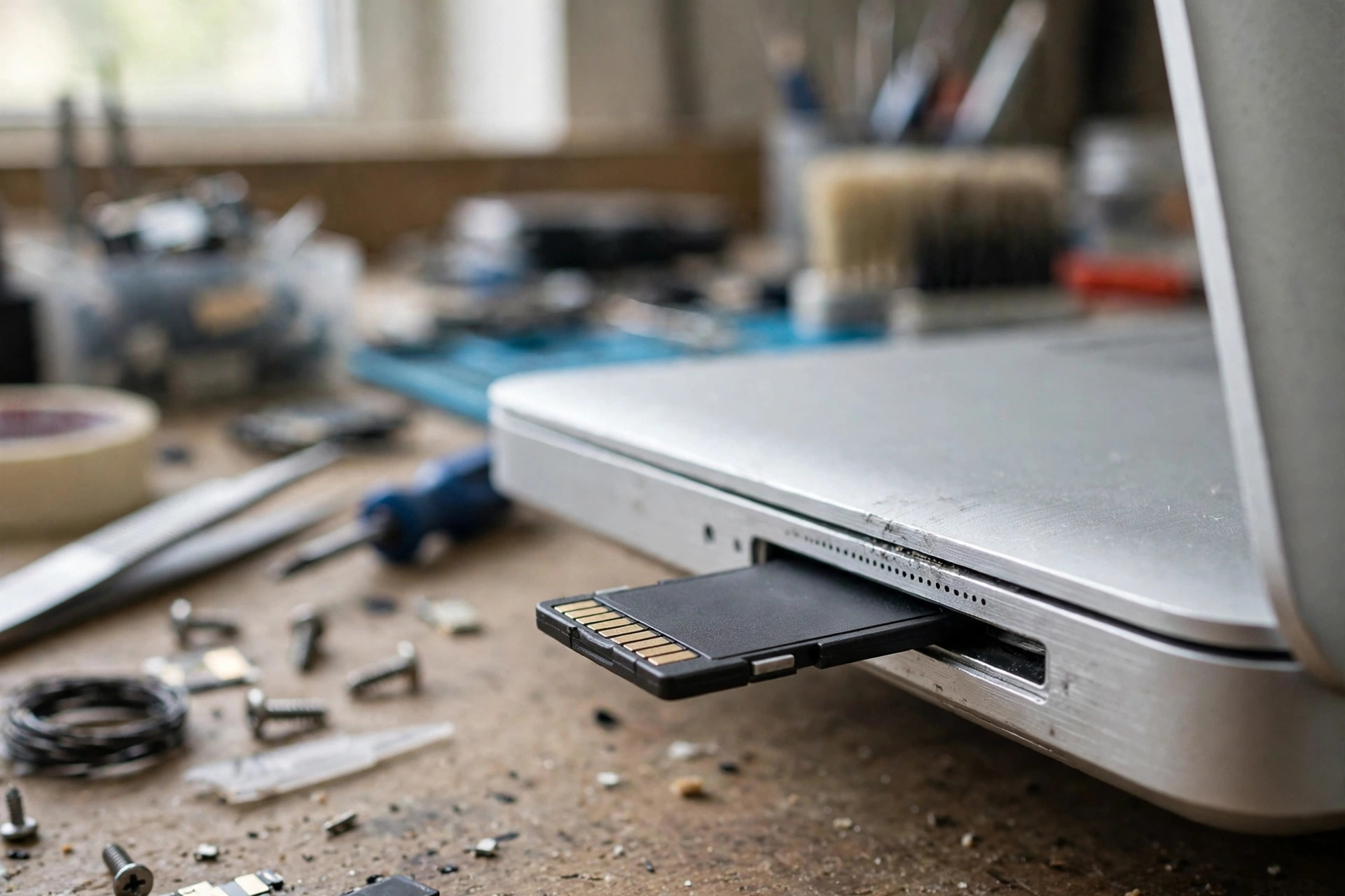
A laptop SD card slot that cannot see a card, can see it but cannot write to it, only recognises a card when it is held at a particular angle, or runs a fast card at a conspicuously slow speed, usually sends the reader straight to the obvious suspects: change the card, format the card, reinstall the driver, or declare the card dead. This guide focuses on one layer only: the physical layer of the SD card slot built into the laptop itself. By the physical layer we mean the slot structure, the push-push eject mechanism, the contacts, the card-detect switch, the write-protect detect switch, the second row of contacts, the solder joints, the flex cable and the daughterboard, and whether any of them is damaged, loose, deformed, worn, oxidised or obstructed by foreign material. When the physical layer is at fault, no amount of software work will genuinely fix it. Conversely, when the driver, the file system or the card itself is at fault, replacing the slot will not help either. The value of an advanced diagnosis is precisely that it establishes which layer the fault sits in, instead of jumping to a conclusion from a single symptom.
This guide has a clear division of labour with the basic guide. The basic guide covers what most readers meet first: a card that is not fully inserted, a damaged card, file-system errors, driver and settings problems, and the basic flow of formatting and backup. This is the advanced guide. It assumes the basic elimination has already been done, and its focus is whether the slot itself has failed, which part of the slot has failed, how to prove that it is that part, and whether to repair it, replace it, or switch to an external reader. Basic checks appear here only as control steps inside the layered elimination, not as the main body. If you have not yet done the most basic elimination — trying another known-good card, trying the same card in another machine, confirming that the data on the card is backed up — do that first, and then use the layered method in this guide to narrow the fault down. Before any test that could affect the data on a card, the risk must be stated plainly: repeated insertion and removal, formatting and write tests can all make data that is still readable today harder to recover tomorrow. Important data gets backed up first. That order is not optional.
Every operation in this guide that involves opening the machine, measuring, soldering, replacing a slot, or inspecting motherboard solder joints and traces is for professional inspection. Readers must not attempt those operations themselves. What readers can safely do is limited to visual inspection after shutdown and disconnection from power, swapping cards, cross-testing in another machine, checking the device status shown by the system, and backing up data. If you see charring, smell burning, see smoke, find the slot blackened or melted, or find a card abnormally hot, stop using that slot at once. Do not insert another card, and do not keep inserting and removing cards to test it. If liquid ingress is suspected, disconnect power first and do not keep powering the machine on to test it. Never poke inside a slot with a metal pin, a toothpick or any other hard object to prod or straighten contacts. A bent contact is easily turned into a broken contact, and a repairable slot into a slot that needs replacement.
1. A map of the link: six stages from the card to the system
Before any layering, you need a map. From an SD card to the operating system, a card-reading link can be divided into six stages. First, the card itself, including its internal controller and flash memory. Second, the contacts and mechanical structure inside the slot. Third, the path from the slot through solder joints, a flex cable or a daughterboard to the mainboard. Fourth, the SD controller or multi-function card-reader controller on the mainboard. Fifth, the driver and the operating system, which enumerate the device and mount the volume. Sixth, the file system and the application layer. A fault at any one of these stages can present as "the card cannot be read", but the repair direction is completely different in each case. The point of layered elimination is to change one variable at a time and narrow the range stage by stage, rather than condemning a part on the strength of a single symptom.
One concept must be established first: a slot exists in two forms, and the repair direction is different for each. In the first form, the slot is soldered directly to the mainboard, so a failed slot has to be dealt with on the mainboard. In the second form, the slot sits on a small daughterboard connected by a flex cable, and that daughterboard may also carry other interfaces, such as a USB port or an indicator light, so a failed slot can sometimes be fixed by replacing the daughterboard alone, without touching the mainboard. Before inspecting anything, check the service documentation or manual for your model to establish which form yours is. Do not assume that all machines are the same. The sections below treat the direct-soldered and daughterboard forms separately where it matters, and the decision framework follows the same split.
2. Slot anatomy: a full-size SD slot and a microSD slot are fundamentally different parts
A full-size SD slot and a microSD slot differ only in size at a glance. In reality they are two different structures, with different contact layouts and different mechanical designs, and they must not be treated as interchangeable.
| Item | Full-size SD slot | microSD slot |
|---|---|---|
| Card size and insertion | The card is larger, easy to grip, inserts deeply, and runs in a longer guide channel | The card is tiny, inserts shallowly, runs in a short guide channel, and is harder to push in straight |
| Eject method | Mostly a push-push mechanism: push in to latch, push again to eject; some use a friction type pulled out with a fingernail | Almost always push-push, because the card is too small for a friction type to be pulled out reliably; some machines use a spring tray that needs an eject pin |
| Card-detect switch | Usually a dedicated card-detect switch, triggered only when the card is fully inserted | Also a card-detect switch, but smaller, with a shorter travel, and therefore more prone to false triggering |
| Write-protect detect switch | Present, because a full-size SD card has a write-protect slider on its side, and the slot needs a switch to sense the slider position | Absent, because a microSD card has no write-protect slider, so the slot has no corresponding switch; when a microSD card is used in a full-size slot through an adapter, the write-protect state depends on the adapter |
| Second row of contacts | Newer full-size slots have a second row of contacts for the second row on faster cards | Newer microSD slots also have a second row of contacts, but the contacts are smaller and more densely packed, so wear and deformation matter more |
| Most common failure points | Push-push latch fatigue, first-row contact wear, write-protect switch false triggering | Bent contacts, push-push spring fatigue, card-detect switch contact failure, damage from angled insertion |
The microSD slot has a different characteristic problem: the card is so small that it is hard to judge by feel whether it is fully inserted. Not inserted deeply enough, and the card-detect switch never triggers, so the system never knows a card is present at all. Inserted too deeply or at an angle, and the contacts can be bent. Tray-type microSD slots need separate attention: a deformed tray, or a loose metal spring inside the tray, makes contact pressure unstable. Before inspecting a microSD slot, establish whether your machine uses a direct-insert type or a tray type, because the inspection priorities differ.
3. Contact assignment: which pin fails decides which symptom appears
The standard contact layout of a full-size SD card must be recognised before any failure can be discussed without confusion. The table below uses the standard order of the contact fingers on the card itself. Note that the numbering of the card's fingers is not the same thing as the routing order inside a particular slot, and the two must not be confused.
| Card contact | Signal name | Function |
|---|---|---|
| 1 | DAT3 | Third data line, also used as a card-detect line in some modes |
| 2 | CMD | Command line, carrying commands and responses between host and card |
| 3 | VSS1 | Ground |
| 4 | VDD | Power supply |
| 5 | CLK | Clock line |
| 6 | VSS2 | Ground |
| 7 | DAT0 | First data line |
| 8 | DAT1 | Second data line |
| 9 | DAT2 | Fourth data line |
The second row of contacts is the key to the faster speed modes. Newer high-speed cards carry an additional row of contacts on the card body, and matching slots carry an additional row of contacts in the corresponding position, using differential signalling to carry data at a higher speed than the traditional first-row mode. This design creates a very important layering property: when the second row fails, the card does not disappear. It falls back to the traditional first-row mode and keeps working, noticeably slower, and the system will not necessarily show any warning at all. What the reader sees is this: the same fast card copies quickly in another machine and slowly in this one, or the speed difference between an old card and a new fast card in the same machine is far smaller than a fast card should show. That "works but slower" pattern can be caused by wear, bending, oxidation or foreign material on the second-row contacts, or by a card that is not inserted deeply enough for the second row to touch. The way to separate those causes is set out in the elimination section. Its core is a two-way comparison: the same card's speed in another known-good machine, and another known-good fast card's speed in this machine. Only both comparisons together can narrow suspicion to the slot's second row. There is also a trap in the opposite direction, and it must be stated: "this card runs slowly in this machine" does not mean the slot's second row is broken, because the slot may have no second row at all. Older models support only the traditional mode, and a fast card inserted into such a slot will simply run in the traditional mode. That is a model specification limit, not a fault. Before checking anything, consult the documentation for your model to establish which speed modes the slot supports. Do not treat a specification ceiling as a failure.
4. The push-push eject mechanism: how springs and latches tire
The push-push mechanism is the most overlooked failure point in an SD slot, precisely because it carries no data, so readers rarely suspect it. The principle is straightforward. The card is pushed in, and a movable latch inside the slot hooks into a notch on the side of the card, holding it in place. Push again, the latch swings clear, and a spring pushes the card out part of the way so that fingers can pull it out. Two parts in this mechanism tire with use. The first is the spring, which loses force after long cycles of compression and release. The second is the latch and its pivot, which wears round through friction, so that the force holding the card falls.
Spring fatigue shows itself in three stages. In the early stage, the eject force weakens: one push only ejects the card a short way, and a fingernail is needed to pull it out, but reading itself is still normal, because contact pressure is not yet affected. In the middle stage, latching becomes unstable: the card reaches the bottom of the slot but does not lock firmly, and a light touch on the machine or a small movement shifts the card slightly, changing contact pressure and producing intermittent disconnection. In the late stage, the card either will not lock at all, or will not eject at all: it jams in the slot, or it springs straight back out as soon as it is released. That gradual progression is exactly what separates a physical failure from a driver problem. A driver problem is usually either working or not working. It does not behave as "works while held, fails when released".
Latch wear is separated from card wear by one test: change the card. If the notch on the side of the card is worn round, a different card will latch firmly. If the latch inside the slot is worn round, several good cards will all fail to latch. This is the same distinction made for the plug latch and the receptacle latch in the Ethernet port guide, and the reasoning transfers directly: test with another card first, and only when several good cards fail to latch does suspicion point at the slot. Never write that a slot that will not latch means the mainboard must be replaced, and never improvise a fix with tape, paper packing or tying the card in place. A card held under a sideways force for a long time damages the contacts and the latch further, and a card wedged into a slot can jam so badly that removing it tears the contacts.
5. The card-detect switch and the write-protect switch: the two switches most prone to false triggering
Besides the contacts that carry data, a slot contains two mechanical switches. Neither carries data, but either one can produce a completely misleading system message.
The card-detect switch tells the controller that a card is present. When a card is fully inserted, the card body opens or presses the switch, its state changes, and only then does the controller power the card and begin initialisation. A failing card-detect switch shows itself in three ways. First, a card is inserted and the system shows no response at all, with neither the reader nor the card appearing in the device list, because the controller simply does not know a card is there. Second, the card is recognised intermittently: a slight movement makes it vanish, and moving it back makes it reappear, because the switch contact is unstable and the controller keeps believing that a card is being inserted and removed. Third, after the card is removed, the system still believes a card is present, leaving behind a drive letter that cannot be accessed, because the switch is stuck in the "card present" position and never springs back. All three presentations are easily misdiagnosed as driver or system problems, because what the reader sees is a system-level message, and the source is only a tiny mechanical switch.
The write-protect switch senses the position of the write-protect slider on the side of a full-size SD card. False triggering of this switch runs in two directions, and both are misleading. The first direction is false write protection: the slider is plainly in the writable position, but the system says the card is write-protected, so nothing can be written, deleted or formatted. The causes can be a bent or worn write-protect switch, a switch held in the locked position by foreign material, a card that is not inserted deeply enough for the slider to line up with the switch, or a loose slider on the card itself that is pushed into the locked position by the slot wall during insertion. The second direction is genuine write protection being ignored: the slider is in the locked position, but the system writes anyway. This is rarer, and it usually means the switch is damaged beyond sensing the slider, or that the slot has no write-protect switch at all. The key test for false write protection is simple, but it must be done in order. First, check the slider position and confirm it is on the writable side. Second, try another known-good card in the same slot and see whether the same slot also reports write protection. Third, put the same card into another known-good machine and see whether it also reports write protection. Only those three results together can separate a slider problem, a slot switch problem, and a system or driver problem. Never format a card the moment write protection appears. Formatting will not repair a mechanical switch, and it can destroy the data on the card.
6. Why slots fail: the remaining failure mechanisms, one by one
Besides the eject mechanism and the two switches, the following mechanisms must each be described with their mechanism, typical symptoms and first separation, not merely listed by name. In practice these mechanisms rarely appear alone. A common combination is angled insertion bending a contact, the bent contact making insertion depth unstable, the unstable depth making the card-detect switch trigger intermittently, and the leverage on the slot cracking a solder joint at the same time. One symptom can therefore sit on several layers at once. The point of layered elimination is to narrow the range, not to convict a part on a single test.
Mechanism one: bent, collapsed and broken contacts
Bending is caused by angled insertion, forced insertion, or a card whose gold fingers are burred or deformed, pushing an individual contact out of line. A bent contact may touch its neighbour and cause a short circuit, or may miss the card's finger entirely and cause an open circuit. Collapse is a contact pressed beyond its elastic limit, permanently deformed so that it never springs back to its original position, and visibly lower than its neighbours. Breakage is fatigue fracture at the contact root, or a contact torn off by force. A broken contact usually retreats deep into the slot and may not be immediately visible to the naked eye. It needs a magnifier and a torch held at an angle, comparing the heights of all the contacts for consistency. Typical symptoms are recognition only at a particular angle, disconnection on the slightest touch to the machine, a fast card falling back to a slow speed, and one contact visibly lower than the others, bent, or missing a corner. Inspection is visual only. Never use a metal needle to pry or straighten a contact.
Mechanism two: contact wear and oxidation
Contact surfaces are generally plated, and the plating exists to prevent oxidation and keep contact resistance low. Repeated insertion and removal wears the plating away and exposes the base metal. Once exposed to oxygen and moisture, the base metal forms oxides. High humidity, salt and sulphur-bearing pollutants accelerate the process, and the products conduct far worse than the pure metal, forming a thin insulating layer on the contact surface that raises contact resistance. Worn plating, pinholes in the plating and edges where the base metal is exposed all give corrosion an entry point. Fretting wear is part of the same chain: extremely small relative movement between the card and the slot, from vibration, thermal expansion and contraction, or moving the machine, wears the plating, exposes the base metal, which then oxidises, and the oxide debris accumulates on the contact surface, in a cycle of wear, oxidation and rising resistance. Typical symptoms are instability on first use after a long idle period in a humid environment, intermittent behaviour, and contacts that look dull, darkened, greenish or powdery. Colour is only a reference, never a conviction on its own. In separation terms, oxidation usually affects a whole group of contacts or several contacts at once, rather than a single broken contact, and it stays with the same machine and the same slot after card and machine cross-tests. Do not instruct readers to scrape contacts with a metal tool or to pour an unknown cleaning fluid into the slot. The correct statement is that suspected oxidation is an inspection item, handled by the inspection service. Scraping by hand can wear through the remaining plating and bend contacts, turning a repairable slot into an unrepairable one. Alcohol or contact cleaner poured into a slot can dissolve plastics, leave conductive residue and accelerate corrosion. Cleaning is for the inspection service to judge against the slot material. Readers must not pour liquid into a slot.
Mechanism three: SD and microSD adapter fit problems
Many readers use a microSD card in an adapter inside a full-size SD slot. That combination adds a layer of contact: one layer between the microSD card and the contacts inside the adapter, and another layer between the adapter's fingers and the full-size slot. Poor contact at either layer presents as a full-size slot problem, but the real cause may be only the adapter. Common adapter problems include worn contacts inside the adapter, an adapter that is slightly thin or out of tolerance so that insertion depth is inaccurate, a loose or missing write-protect slider on the adapter that makes the write-protect switch sense wrongly, and a deformed adapter body that the slot latch cannot grip. Separation must break the adapter layer apart for testing: test the same microSD card directly in an external microSD reader, then test it through the adapter in the full-size slot. If the two results differ, suspicion points at the adapter or at the fit between the adapter and the full-size slot, not at the microSD card itself. Then test a full-size SD card directly in the same slot. If the full-size card works normally, suspicion of an adapter fit problem rises further. Never write an adapter test result up as a failed full-size slot. That is one of the most common misdiagnoses in this area.
Need a laptop repair expert?
Free diagnosis · Transparent pricing · No fix, no fee · 180-day warranty
Mechanism four: dust, foreign material and liquid
Dust, paper fragments and food debris inside a slot prevent a card from seating fully, so that individual contacts never touch. Liquid, from a spilled drink, rain or condensation, can cause short circuits and corrosion, and the residue left after the liquid dries keeps affecting contact. A dropped laptop, pressure inside a bag, or a card yanked while the machine is dragged, can crack a slot shell or stress its solder feet. Typical symptoms are sudden onset after a period of normal use, a card that seats unevenly or not fully, visible foreign material, or a history of liquid exposure. The handling rule must be stated: if liquid is suspected, disconnect power first, and do not keep powering on to test. Do not pick at foreign material with a metal tool while power is connected. Inspection is visual only after shutdown and disconnection, and compressed air must not be blasted into the slot at close range, which can drive foreign material deeper. Liquid cleaner must not be poured into a slot.
Mechanism five: cracked solder joints, loose flex cables and daughterboard problems
A slot is usually surface-mounted to the mainboard or to a daughterboard, and its solder joints carry both the electrical connection and the mechanical fixing. Insertion force, pulling force on a card and flexing of the machine body all pass through the slot body into the joints, which makes slot solder joints a high-risk location. A cold joint is a joint where the solder never fully melted and flowed during manufacture, so that the bond between the joint and the pad or pin is weak, and the surface can look dull, rough, cracked or voided. Even if it passes factory testing, long cycles of thermal expansion and contraction, vibration and mechanical stress transmitted through insertion can widen micro-cracks until the joint opens intermittently or completely. Pad lift is worse than a cracked joint, because the copper foil of the board itself is torn away, and the repair difficulty and risk rise sharply. A daughterboard structure adds two more failure points: a loose flex-cable connector or oxidised flex-cable fingers, whose presentation is very similar to a slot contact problem but whose cause sits in the cable; and a broken trace on the daughterboard itself, or another component on the daughterboard. Typical symptoms are the classic intermittent pattern: pressing near the slot changes the symptoms, cold and hot states behave differently, and moving the machine breaks the connection. Sometimes light pressure on the slot area briefly restores operation. In appearance, a crack or a dull joint is sometimes visible, but a micro-crack is often invisible to the naked eye. Do not instruct readers to reflow a joint with a hot-air gun. Heating profiles, temperatures and the risk to neighbouring components belong to professional repair. This guide lists a suspected solder problem as a disassembly inspection item only.
Mechanism six: loose or deformed slot shells
The metal or plastic shell around a slot provides mechanical fixing and shielding. A loose shell, a broken solder foot, or a dented shell lets the whole slot move on the mainboard or daughterboard. Insertion depth and angle then vary every time, contact pressure becomes unstable, and shielding and grounding integrity fall..
7. Four-layer distinction: which layer is at fault
With so many mechanisms described, readers need a table that maps symptoms to a suspected layer. The table below is one of the core tables of this guide. The layers number four, and they must be counted correctly: the physical contact layer, the signal and speed layer, the daughterboard, flex-cable and solder layer, and the controller and driver logic layer.
| Suspected layer | Common clues | What you will see | First separation, without disassembly |
|---|---|---|---|
| Physical contact layer, including contacts, eject mechanism, card-detect switch, write-protect switch and foreign material | Angle-sensitive, works only while held, will not latch, reports write protection, changes when the card is changed | Intermittent recognition, intermittent disconnection, false write protection, card ejecting or jamming | Visual inspection, trying a known-good card, trying the same card in another machine, recording which action makes the symptom appear or disappear |
| Signal and speed layer, including the second row of contacts and data-line contact | Fast card runs slowly, large-file copies produce errors, old card normal but new card slow | Card recognised but speed reduced, transfers interrupted, data width fallen from four lines to one line | Comparing the same card's speed in another machine, comparing another fast card's speed in this machine |
| Daughterboard, flex-cable and solder layer | Pressing near the slot changes symptoms, cold and hot states differ, the whole slot is loose, other interfaces on the same daughterboard are also abnormal | Intermittent open circuit, works sometimes and not others, related to force on the machine body | Recording the relationship between pressing, temperature, vibration and symptoms; do not heat or pry solder joints yourself |
| Controller and driver logic layer | Device present or absent in Device Manager, driver state, problem started after a system update | Device disappeared, driver error, system does not recognise the reader itself at all | Checking whether the reader device appears, checking driver state, comparing the same card in another machine |
8. Five-layer elimination: do not change the order
The principle is to start with steps that need no disassembly, cost the least and are reversible. Write down the result of each layer before moving on. Do not change every variable at once, or nobody will ever know which one was the real cause. Change one variable at a time, and record recognition state, speed behaviour and stability each time. The five layers are: appearance and mechanics, card and adapter cross-testing, speed and second-row comparison, solder and daughterboard assessment, and controller and driver logic confirmation.
Layer 1: appearance and mechanics
After shutdown, after disconnecting power and removing the card, inspect without using a metal tool inside a powered slot. Look for contacts that are bent, broken, visibly lower than their neighbours, or discoloured. Check whether the eject mechanism gives a latching feel when pressed, and whether a second press ejects the card. Check whether the slot shell is loose or dented. Check for foreign material inside the slot. Check whether the card seats fully, and whether it rocks noticeably once inserted. Record the relationship between symptoms and actions: which angle works and which does not, whether holding the card works and releasing it fails. A tray-type microSD slot needs separate attention to tray deformation and loose tray springs, and must not be judged by the feel of a direct-insert slot.
Layer 2: card and adapter cross-testing
Test with a known-good card, one that has first been verified as normal in another machine. Do not substitute "newly bought" for "verified". Run the four-way cross-test: original card in the original slot, good card in the original slot, original card in another machine, good card in another machine. Each time, record whether the card is recognised, whether reading and writing are normal, and how long stability lasts. Readers using an adapter must add one more cell: test the same microSD card in an external microSD reader, so that the adapter layer is separated before anyone blames the slot. Write-protect problems are also handled in this layer: check the slider position, test a good card in the same slot, and test the same card in another known-good machine. Only those three comparisons together can separate a slider problem, a switch problem and a system problem.
Layer 3: speed and second-row comparison
On the basis of the Layer 2 results, compare speed behaviour. The key question is whether the card is recognised and readable, but clearly slower than the same card in another machine, or whether the speed difference between a fast card and an old card in the same machine is implausibly small. That combination raises suspicion of the second-row contact layer. The conclusion at this layer can only be stated as suspicion of the second-row layer, needing inspection to confirm. It must not be written as a diagnosis. One reminder belongs here: before comparing, confirm from the model documentation what speed modes the slot supports. An older model that supports only the traditional mode will run a fast card in the traditional mode by design. That is a specification limit, not a second-row failure, and it must not be written up as one.
Layer 4: solder and daughterboard
Record the relationship between pressing, temperature, vibration and symptoms. Light pressure near the slot changing the symptoms, normal behaviour when cold and failure when hot, or disconnection when the machine body moves, all point at the solder or trace layer. A loose shell belongs in this layer's assessment as well, because a loose shell and stressed joints commonly appear together. For daughterboard models, pay separate attention to whether other interfaces on the same daughterboard, such as a USB port on the same board, show intermittent problems at the same time. If interfaces on the same board fail together, suspicion of the flex-cable or daughterboard layer rises. If only the slot fails, suspicion stays concentrated on the slot itself. In principle this layer already requires disassembly, so this guide lists inspection items only. It does not give disassembly, heating or soldering steps. Different models fix their slots differently, lay out their boards differently, and tolerate heat differently around neighbouring components, so a generic tutorial would mislead. Readers who suspect a solder problem should record the pressing, temperature and symptom relationship and hand it to the inspection service, rather than heating or prying joints themselves.
Layer 5: controller and driver logic confirmation
Confirm whether the reader device itself appears, for example the reader controller in Device Manager or system information, along with its driver state and whether anything changed after a system update. Do not instruct readers to force a speed mode one-sidedly or to change driver settings at random, since one-sided settings can create further problems. Run the comparison: the same card in the same machine works through an external reader but not through the built-in slot, which points the evidence at the built-in link; the same card fails in another machine as well, which points first at the card, the adapter or the file system. After excluding driver problems following a system update and power management putting the controller to sleep, and the fault still concentrates on the same slot, suspicion narrows to the controller chip itself or its power supply, clock and other mainboard-level matters. Those are likewise inspection matters, and a system status alone must never be written up as a dead controller. Only when this layer is complete is the five-layer elimination finished. Skipping any earlier layer leaves a gap in the conclusion.
9. Common misdiagnoses and traps
The following eight misdiagnoses should each be named, so that readers can check whether they have fallen into one. First, blaming the card: condemning the card without cross-testing, then finding that a replacement card shows the same problem, or that the original card was never faulty and the slot contact was. Second, treating formatting as a repair: formatting a card that is not recognised, reports write protection or disconnects intermittently. Formatting only addresses the file-system layer. It repairs no contact, switch or solder problem, and it can destroy the data on the card. Important data must be backed up first. Third, treating write protection as a dead card: assuming that a write-protection message means the card is locked or ruined, when very often it is only a false trigger of the write-protect switch, a wrong slider position, or a loose adapter slider. Follow the three-way comparison in Layer 2 before concluding anything. Fourth, treating an adapter problem as a slot problem: writing up a failure seen through an adapter as a failed full-size slot, without breaking the adapter layer apart for testing, as described in the adapter section. Fifth, treating slowness as a slow card: blaming the card for slow speed while ignoring second-row contact failure, data-line contact failure and the model's own specification ceiling. Compare speed modes before concluding. Sixth, treating recognition as health: assuming that a recognised card proves a healthy slot. That is wrong, because data-line contact failure and second-row failure both leave the card recognised, only slower and less stable. Seventh, turning cleaning into secondary damage: prying with a metal needle, scraping with a hard object, pouring liquid into the slot, or heating a solder joint. Any of these can bend contacts, wear through plating, cause a short circuit or damage neighbouring components. This guide recommends only shutdown visual inspection and cross-testing. It gives no invasive do-it-yourself repair steps. Eighth, convicting on a single symptom: a card that is not recognised can be caused by contacts, the card-detect switch, the flex cable, solder joints, the daughterboard, the controller, the driver, the card itself and several other causes. Cross-testing must narrow it down. No single symptom writes a conclusion. Two further traps, not counted in the eight above, deserve the same warning. A driver reinstall that changes nothing does not prove a hardware fault. It only excludes the driver layer, and the hardware layers still contain contacts, switches, flex cables, solder joints, daughterboards and controllers, so it cannot jump straight to mainboard replacement. And an external reader that works does not mean the original slot needs no repair. An external reader bypasses the original slot. It does not repair it, as the decision framework below explains.
10. Hong Kong conditions: why failures are especially likely here
Hong Kong conditions must be described realistically, not as a generic article. First, humidity and oxidation. Hong Kong's high humidity raises the risk of contact oxidation and corrosion compared with drier regions, especially for machines kept near windows, in the path of air-conditioner condensation, or in damp rooms. An infrequently used interface is actually more vulnerable to a film forming on its contact surface: a slot that goes months without a card inserted gets no insertion friction to wipe the surface film away, so an oxide layer can quietly accumulate, and the first use after a long idle period is the moment the failure appears. Repeated air-conditioner on-off cycles make condensation inside a slot likely, and moisture plus sulphur-bearing air plus pinholes in the plating is exactly the environment for pore corrosion. The preventive advice is to keep the storage environment dry, not to leave a card inserted under force for a long time, to inspect periodically rather than to run powered tests periodically, and never to clean with an unknown liquid.
Second, commuting insertion cycles and frequent camera-card swapping. Carrying a machine to work or school every day and inserting and removing cards in different places raises both the insertion count and the chance of angled force. Photography and video users who swap the same card between a camera and a laptop several times a day run the eject mechanism and contact clock faster still. Pressure inside a bag, and closing the lid or packing the machine away with a card still inserted, transmit force into the slot and its solder joints. The preventive advice is to press once and let the card eject before pulling, to insert and remove straight, never to yank a card body by force, to remove the card before packing, and never to close the lid and carry the machine with a card inserted.
Third, leaving a card inserted as permanent storage. Some users leave an SD card in the slot as extra storage. That habit has two costs. First, the card body becomes a lever, and every movement of the machine transmits force into the slot. Second, the card sits in the machine's heat for long periods, and differing thermal expansion between the contacts and the card body accelerates fretting wear. The correct habit is to insert a card when it is needed and remove it when it is done, not to treat the slot as a permanent storage bay.
Fourth, adapter overuse. Long-term reliance on an adapter, an adapter that is slightly thin or deformed, or an adapter whose write-protect slider is loose, can turn a temporary combination into a long-term contact problem. An adapter has contacts of its own, and the same physical failure mechanisms apply to it. Replacing a failed adapter is cheaper than repairing a slot, but an adapter is not a repair. It adds a variable, and before blaming the slot, the adapter layer must be separated by testing, as described above.
Fifth, thin machines and daughterboard reminders. Some ultra-thin models have no built-in SD slot at all and rely on an external reader. In those machines, the physical failure location moves from the body slot to the external reader and the USB interface. Some models carry the slot on a daughterboard, and daughterboard part numbers, flex-cable lengths and interface configurations vary by model. No single generic part fits all machines. Mainboard-level repair likewise requires confirming trace, pad and neighbouring component condition first. On price, this guide writes only the published starting-price references and the written-quote-after-inspection principle. Estimating from a model name alone is easy to get wrong, because only opening the machine reveals whether the fault is in the slot, the solder joints, the flex cable, the daughterboard or the controller.
11. Repair, replacement and substitution decision framework
The decision table must not be written as a blanket recommendation to replace or to use an external reader in all cases. It must follow the inspection result, case by case. Prices are always subject to a written quotation after inspection, and this guide writes no specific price for slot repair itself, because only opening the machine reveals whether the fault is in the slot, the solder joints, the flex cable, the daughterboard or the controller.
| Situation | More reasonable direction | Trade-offs that must be stated |
|---|---|---|
| Problem proven to be in the card itself or the adapter | Replace the card or the adapter, depending on the test result | Lowest cost; but confirm that the replacement card has been verified as normal, and do not treat an unverified new card as a conclusion |
| Problem proven to be in the slot contacts, eject mechanism, card-detect switch or write-protect switch, with no further pad damage seen | Replace the slot alone, whether direct-soldered or on a daughterboard, depending on the model | A disassembly repair; the part number must match the model, it is not a generic part; varies by model, and the model documentation is authoritative; price subject to a written quotation after inspection |
| Problem pointing at a loose flex cable, oxidised flex-cable fingers or the daughterboard layer | Replace the flex cable or the daughterboard, depending on the inspection result | Advantage: the mainboard need not be touched; but daughterboard part numbers and flex-cable specifications vary by model and must be matched against the model documentation, and a similar-looking part is not a substitute |
| Problem pointing at cracked solder joints, broken traces or damaged pads | Mainboard-level repair assessment, including solder-joint work, trace inspection and jumper-wire assessment | A jumper wire is only one option the inspection service assesses when a trace break is located and surrounding conditions permit; it is not a generic practice; if pads or board layers are already damaged, the repair scope and difficulty rise, and the inspection result governs |
| Original slot damage is extensive, repair value is doubtful, or the user needs card reading restored immediately | External reader as a substitute | Advantage: immediately usable, no disassembly; disadvantages: it does not repair the original slot, speed and stability depend on the external reader's specification, interface bandwidth and driver, and a reader left hanging under force can become a new damage point; check the reader's stated supported speed modes and system requirements before buying |
| Several layers damaged at once, for example a loose slot plus cracked solder joints plus a controller abnormality, or other mainboard problems as well | Comprehensive judgement based on the full-machine inspection result | Do not assemble separate per-item quotations into a total; use the written quotation after inspection, and let the user decide whether to repair, replace or substitute |
| Machine itself has reached its replacement cycle, or other ageing problems remain after repair | Compare repair against replacement together | The comparison basis should be the inspection result and the written quotation, not a single symptom; this guide gives no replacement model recommendations |
Four questions for the reader at the decision point, usable as a closing checklist. First, has cross-testing already proven that the problem concentrates on the same slot in the laptop? Second, is the damage on a single layer, or on several layers at once? Third, does the user want the original slot repaired, or card reading restored immediately? The two answers can differ. Fourth, has the written quotation and repair scope after inspection been stated clearly before deciding? All model differences must be stated as varying by model, with the model documentation authoritative, and no phenomenon seen on one brand may be written as a general conclusion.
12. Teaching examples, none of which are real cases
The following three examples are purely teaching scenarios, not real cases, and they represent no real user and no real repair record. Example one, a teaching scenario and not a real case: a laptop used daily for commuting only recognises an SD card when the card is held at a particular angle, and two verified good cards behave the same way, while the slot's eject mechanism also fails to latch. Following the five-layer process, the card layer is already excluded, and suspicion points at the slot contact layer, including the contacts and the eject mechanism. Inspection must confirm whether this is a slot-only replacement or whether solder joints are involved. Example two, a teaching scenario and not a real case: a laptop kept in a humid environment and rarely using its SD slot reports write protection on first use after a long idle period, although the slider is plainly in the writable position. After card and machine comparison, suspicion points at a false trigger of the slot's write-protect switch. Inspection must narrow it down. It must not be written up directly as a dead card or a system problem, and the card must certainly not be formatted at once. Example three, a teaching scenario and not a real case: a laptop's SD slot feels loose as a whole, light pressure near the slot changes the symptoms, and other interfaces on the same daughterboard fail intermittently too. That combination points at the shell, solder-joint, flex-cable and daughterboard layers. Simply changing the card or switching to an external reader is not an adequate response. The repair scope should follow the inspection result.
13. Preparing for inspection, and related links
Before sending a machine for inspection, prepare the following information so that the inspection service can narrow the range as quickly as possible: the model and the slot form, including whether it is a full-size slot or a microSD slot, direct-insert or tray type, direct-soldered or on a daughterboard; how the symptoms appear, including which angle works and which does not, whether holding the card works and releasing it fails, and whether cold and hot states differ; the recognition state, including whether the system recognises the card, what the speed behaviour is, and whether any write-protection message appears; the cross-test results already obtained, including which cards were tried, whether an adapter was used, and how the same card behaved in another machine; and background such as liquid exposure, drops, or a habit of carrying the machine with a card inserted. This information is not meant to let readers diagnose the fault themselves. It lets the inspection service start from the suspected layer instead of repeating basic elimination from zero.
For related links, readers can first read pricing and service scope to understand the service framework, with all prices subject to a written quotation after inspection; readers who need to arrange an inspection can go to diagnostic booking for the inspection arrangements. Disassembly, measurement and soldering are for professional inspection. Readers only do visual observation and cross-testing. That sentence is the safety line running through the whole guide, and it does not change because any section is written in depth.
If inspection finds other components with problems at the same time, the published starting-price references are: battery from HK$580, screen from HK$1,280, keyboard from HK$480, and mainboard chip-level repair from HK$880. Everything else is subject to a written quotation after inspection.
The shop details are as follows: Room 1209, Dalton Centre, Shek Mun, Shatin, telephone +852 2186 8010, WhatsApp +852 6558 6806, business hours 12:00–19:00. Before seeking help, please complete the non-disassembly parts of the five-layer elimination above, and record the recognition state, speed behaviour and cross-test results. That way inspection can start directly from the suspected layer, instead of repeating basic elimination. What physical failure fears most is not a clean break, but an ambiguous one: the card is recognised, files copy, speed has fallen, and the connection drops now and then, so that everyone assumes the card is simply slow. Separating the contacts, the eject mechanism, the switches, the second row of contacts, the flex cable, the solder joints and the daughterboard, layer by layer, is the first step towards genuinely repairing the original slot.
Frequently asked questions
Q1: The card is recognised, but copying is very slow. Does that mean the slot is broken?
A: Not directly. Recognition only proves that basic communication and power are broadly working. Poor data-line contact, a second-row contact failure, or a model that supports only the traditional mode can all reduce speed. The correct approach is to first confirm from the model documentation which speed modes the slot supports, then compare speed with a known-good fast card and another machine. Only when the same slot is slow with changed cards and changed machines does suspicion narrow to the laptop-side physical layer, after which inspection separates the contacts, the second row, the flex cable and the controller layers.
Q2: The system says the card is write-protected, but the slider is not locked. Is the card dead?
A: Not necessarily. The write-protect slider is only a piece of plastic. The slot senses its position with the write-protect switch, and the host enforces the refusal to write. A wrong slider position, a loose adapter slider, or a bent write-protect switch, or a switch held by foreign material, can all produce false write protection. The correct approach is to first confirm the slider position, then test a known-good card in the same slot, then test the same card in another known-good machine. Only those three comparisons together can separate a slider problem, a switch problem and a system problem. Do not format the card at once. Formatting does not repair a mechanical switch.
Q3: A failure seen through an adapter in a full-size slot: does that mean the full-size slot is broken?
A: No. An adapter combination adds a layer of contact: one layer between the microSD card and the adapter, and one layer between the adapter and the full-size slot. A failure at either layer presents as a full-size slot problem. The correct approach is to break the adapter layer apart for testing: test the same microSD card directly in an external microSD reader, then test a full-size SD card directly in the same slot. Only by comparing those two results can the adapter, the microSD card and the full-size slot be separated.
Q4: An external reader works. Does that mean the original slot needs no repair?
A: No. A working external reader only proves that the card and the system are broadly normal, and that the external reader's own link is normal. It does not prove that the built-in slot is healthy. An external reader bypasses the original slot. It does not repair it. The physical damage in the original slot, such as a loose shell or cracked solder joints, remains. If work depends on the built-in slot, for example a fixed desk setup or frequent camera-card swapping, an external reader is only an interim solution. If the machine is near replacement and card-reading needs are low, an external reader can be a reasonable substitute. Which route to take depends on the inspection result, the written quotation and how much the user depends on card reading, with all prices subject to a written quotation after inspection.
Need Professional Laptop Repair?
Laptop King has 15+ years of repair experience in Shek Mun, Sha Tin. Free diagnosis, transparent pricing, no fix no fee. 180-day warranty for your peace of mind.