📌 Key Takeaways
- •Semiconductor Digest, ball grid array solder-joint reliability study: expansion mismatch causing stress, balls cracking into opens under extremes, and resistance change as a failure definition under temperature cycling. [source](https://sst.semiconductor-digest.com/2002/11/bga-solder-joints/)
- •MDPI Micromachines, inner-ball voids and thermal fatigue reliability: outer-ball thermal fatigue reliability tending lower than inner balls, but larger inner-ball voids acting together with strain accumulation also allowing inner balls to fail first, with failing balls in the outermost two rings. [source](https://www.mdpi.com/2072-666X/14/3/588/htm)
- •MDPI Materials, solder-ball thermal fatigue failure under cyclic thermal stress: interface shear strain concentration as a crack starting position, and the Coffin-Manson model using equivalent viscoplastic strain range as a life assessment basis. [source](https://www.mdpi.com/1996-1944/19/3/640)
- •MDPI Encyclopedia, ball grid array solder-ball fatigue life prediction review: Coffin-Manson as the earliest low-cycle fatigue model from 1954, based on plastic deformation. [source](https://encyclopedia.pub/entry/history/compare_revision/47547/-1)
- •MDPI Electronics, ball grid array solder-ball fatigue life prediction survey: vibration bending boards, raising solder-ball stress toward fatigue failure. [source](https://www.mdpi.com/2079-9292/11/4/542)
1. Scope: this article covers only the solder-joint open layer, after the short-circuit, driver, memory, and sequencing layers
This article applies to one narrow situation, and only when a strict precondition is already met: the mainboard short-circuit layer, the power-sequencing layer, the embedded-controller layer, the charging layer, the memory layer, and the driver and display layers have all been excluded or are being excluded, yet the machine still shows intermittent crashes, no display on start-up, or intermittent faults related to the graphics processor or the platform controller. In other words, the starting point here is not a machine that will not turn on, but a machine where the earlier layers have been shown not to be the break point, or have shown nothing abnormal, while the intermittent fault remains, and only then does the discussion enter the solder-joint layer. If the reader has not worked through layer separation, this article should not be applied directly; the neighbouring articles should be revisited first, their content must not be rewritten here, and this article must not be used as a general guide to every intermittent fault. Order is itself part of the diagnosis: the solder-joint layer carries the highest inspection cost and risk, so it should not be reached before the lower-cost layers have been excluded, and the short-circuit layer carries the highest risk of all, because heating a board that is actually shorted can spread damage, so the short-circuit layer must be excluded before this article is entered at all.
The neighbouring topics below are mentioned only to draw boundaries and are never rewritten. The mainboard short-circuit layer belongs to the previous batch: a short is a low-resistance path where current takes a shortcut, while an open is a path that has broken, and the two run in opposite directions, with entirely different measurement directions, dangers, and handling, so the short-location methods of the previous batch must never be copied over to discuss opens. Graphics artefacts and driver crashes belong to the driver and display layer: that article covers the driver layer and the display layer, this article covers only the solder-joint physical layer, an artefact by itself is not solder-joint evidence, and driver installation and display settings stay with that article. Memory instability stays with the memory layer, the embedded controller stays with the controller layer, power sequencing stays with the sequencing layer, and the charger chip stays with the charging-management layer. Each layer has its own symptom distinctions and exclusion methods, and skipping them to talk about solder joints directly is concluding before separating, which is the first writing error this article opposes.
| Neighbouring layer | What it covers | What this article does not cover |
|---|---|---|
| Mainboard short-circuit layer (previous batch) | Low-resistance paths, protection triggering, abnormal rail resistance to ground | No short-circuit location, injection location, or rail-by-rail short isolation rewritten here |
| Driver and display layer | Driver versions, display settings, artefact classification | No driver installation, driver rollback, or display settings here; an artefact alone is not solder-joint evidence |
| Memory layer | Memory slots, capacity combinations, memory-test errors | No memory-test steps and no slot handling here |
| Embedded-controller layer | Power button, charging indication, fan control, and other controller management functions | Controller failure is not used here as a universal answer; the controller itself is also a ball grid array package, and mistaking a controller problem for a graphics solder-joint problem leads to replacing the wrong chip |
| Power-sequencing layer | Power-on procedure stages and the fixed pattern of power indicators and fan behaviour | No sequencing measurement and no waveform reading rewritten here |
| Charger-chip layer | Charging, battery-versus-adapter switching, charging management | No charging-circuit measurement here; a charging-layer problem can disguise itself as an intermittent crash and must be excluded first |
2. One distinguishing principle: intermittency itself is not a diagnosis, and the solder-joint layer is only one possibility among many
Intermittent crashes, no display on start-up, and intermittent faults related to the graphics processor or the platform controller are not a diagnosis by themselves; they are only a starting point. The solder-joint layer is only one of many possible layers, and it can be pointed to with greater confidence only after the other layers have been excluded and several temperature and mechanical modulation patterns agree. A single symptom, a single improvement on pressing, or a single improvement after heating is never enough to confirm. This principle must hold behind every suspicion paragraph in the whole article: any paragraph that reads as if a single clue equals a solder-joint failure is wrong. The first thing readers should take away is not a part name but an attitude: between a direction for suspicion and a confirmation there lies a whole exclusion procedure and a convergence standard of several agreeing lines of evidence, and skipping that middle road turns even a confident-sounding answer into inference.
Why intermittency misleads so easily lies in the openness of the symptom. The same intermittent pattern can come from poor contact, unstable supply, the memory layer, the driver layer, the sequencing layer, or the short-circuit layer, as well as from a solder-joint open; and one solder-joint problem can present as failure to start, crashing, or one function working only sometimes, rather than always presenting as a single symptom. The unsettled character of the symptom is itself a clue, because a solder joint carries electrical connection, mechanical connection, and part of the heat path at once, and which ball has failed and which pin maps to which function cannot be matched from outward symptoms alone to one particular ball. But a clue is not evidence, and unsettled does not mean the reader may pick whichever answer looks most similar. The correct writing posture is that every symptom form must be followed by the directions that still have to be excluded, so that readers understand why a bench spends time on tests that look unrelated before it can speak of solder-joint suspicion.
One more boundary must be stated at the outset and kept through the whole article: getting better does not mean repaired. The most common explanation for a temporary disappearance of an intermittent fault is that the contact state has temporarily changed, not that the crack has healed. Recovery after a restart, a tap, pressing, or heating only proves that the contact state can change; it does not prove that the cause of the fault has gone away. A genuine repair requires either that the joint form a reliable metallurgical bond again or that the relevant package and board be replaced, and neither is something pressing can achieve. This sentence is also the core of reader safety: treating recovery as repair leaves readers using a machine whose joints are still intermittently open, with important data exposed to sudden crashes at any time, and it can also lead readers to keep a machine going by repeated pressing and heating, which makes crack faces open and close repeatedly, increases the chance of pad separation and crack growth, and makes it harder for the bench to judge the original fault pattern.
3. Terminology first: BGA, joint, open, cold joint, non-wetted open, fatigue crack, underfill, reflow, reball
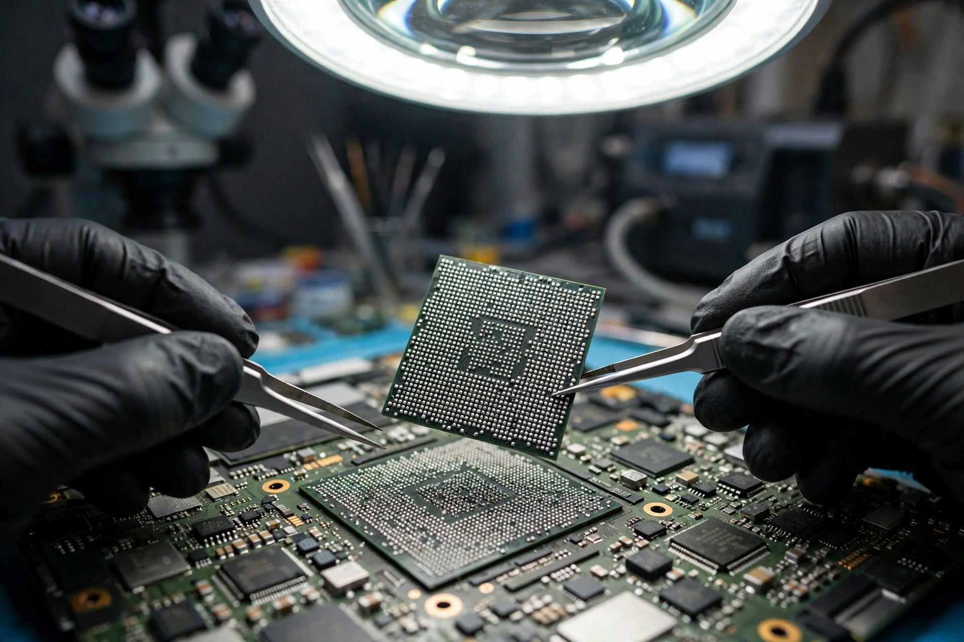
If the terminology is unclear, every later distinction will blur. The first group of words concerns the package and the connection itself. BGA stands for ball grid array, a package whose underside connects to the board through an array of solder balls, numbering in the hundreds, spaced finely, and impossible to observe directly with the naked eye. A solder joint is the connection formed when a solder ball is welded to a pad, and it carries electrical connection and mechanical connection at the same time. An open is a path that has broken, so a signal or a supply cannot pass. Short and open must never be confused: a short is a place that conducts when it should not, while an open is a place that has broken or makes poor contact when it should conduct, and the two differ entirely in measurement direction, danger, and handling. Large chips in a laptop such as the central processor, the graphics processor, and the platform controller commonly use this welded form, but which package a particular machine uses must follow that model's specification, and this article never writes that every laptop processor is a ball grid array package.
The second group of words concerns defect names, which must be kept apart and never lumped together under one vague word. A cold joint is a joint where the solder failed to melt and wet adequately during soldering, so the bond is weak from birth. A non-wetted open is a joint where the ball exists in appearance but has never formed an effective metallurgical bond with the pad, and it belongs to the open category. A fatigue crack is a crack that grows step by step inside a solder ball or at an interface under repeated loading, and it differs from a factory defect. Underfill is the material filled into the gap between chip and board; edge bond seals only the edge, and corner bond reinforces only the four corners, and the three must never be confused. Reflow remelts the existing solder balls and lets them solidify again; reball removes the chip, clears the old solder, plants new solder balls, and solders the chip again. The two differ in substance, and whether the solder material has been replaced is the dividing line, a point the later trap section will compare in detail. Readers do not need to memorise abbreviations; they only need to understand that different names mean different causes, different timing, and different repair meaning, and that lumping them into one word removes all power of distinction from later judgements.
| Term | Meaning | One sentence for the reader |
|---|---|---|
| BGA | Ball grid array package, connecting to the board through a solder-ball array under the chip | The joints hide under the package and cannot be seen by eye, so looking healthy never excludes a joint fault |
| Solder joint | The connection formed when a solder ball is welded to a pad | It is an electrical channel and a mechanical support at once, so one critical ball going open can disable a whole chip |
| Open | A path that has broken, so a signal or a supply cannot pass | It runs opposite to a short, with entirely different measurement direction, danger, and handling |
| Cold joint | Solder that failed to melt and wet adequately during soldering, leaving a weak bond from birth | Already present when the machine leaves the factory, not something that appears only after long use |
| Non-wetted open | A ball present in appearance but never forming an effective metallurgical bond | Belongs to the open category, including non-wetted opens and the head-in-pillow effect |
| Fatigue crack | A crack growing step by step under repeated loading | Appears after a period of use and becomes steadily more frequent |
| Underfill, edge bond, corner bond | Full fill, edge-only sealing, and four-corner reinforcement | The three spread stress to different degrees and must not be lumped as simply having glue |
| Reflow, reball | Remelting the old balls, versus removing the chip and planting new balls | The first replaces no solder material, the second replaces it, and their meaning is entirely different |
4. BGA structure: from top to bottom, where the joints hide, and why a normal-looking board can still have a joint fault
From top to bottom, a ball grid array package has five layers. At the top sits the silicon die, the material with the smallest expansion rate; below it sits the package substrate, the intermediate layer carrying the die, with a middle expansion rate; below that sits the solder-ball array, hundreds of balls arranged under the package; facing each ball sits a copper pad on the board; and at the bottom sits the printed circuit board carrying the whole mainboard, with a larger expansion rate than the chip. The crucial point is that a solder ball is an electrical channel and a mechanical support at the same time. Any one ball carrying a critical signal or supply that goes open can disable the whole chip functionally, while the board can look entirely normal from the outside, with the fan spinning and the indicators lit. That is why a joint fault is hard to judge by appearance, and why looking healthy can never exclude the joint layer. Under one large package there are hundreds of joints, and which ball has failed and which pin maps to which function cannot be matched from outward symptoms alone to one particular ball, and that limit must be stated in the structure section itself, not left to be added later in the diagnosis section.
The farther a solder ball sits from the centre of the package, the larger the relative displacement it experiences under temperature change because of the expansion difference. This concept is called distance to neutral point. The relationship in principle can be written in words: relative displacement is approximately the distance from the centre multiplied by the expansion-coefficient difference multiplied by the temperature change, multiplied further by an empirical correction factor that varies with structure. This article states only the direction of the relationship and substitutes no universal numbers, because the correction factor depends on pad design, substrate structure, and ball height together. The relationship directly explains why corner balls deserve particular attention: when the layers expand asymmetrically, the package bends, a phenomenon called warpage, and warpage is largest at the corners, so corner balls carry shear and tension at the same time. Published research agrees on one tendency: in thermal cycling and drop testing, the outermost balls, especially the corner balls, tend to show lower thermal fatigue reliability than inner balls, and failure positions tend to concentrate in the outermost two rings. But the word tendency must be kept, because there is a verified exception: if inner balls themselves carry larger voids, voids and strain accumulation acting together can make inner balls fail first. Corner-first failure is a tendency, not a law, and any writing that turns the tendency into a law will not be used in this article.
5. Intermetallic compound: a thin continuous layer is a normal bond, and excessive thickness turning brittle is the problem direction
When soldering takes place, solder reacts with the copper pad and forms an intermetallic compound at the interface, with common constituents including copper-tin compounds and, in tin-silver-copper alloys, a silver-tin compound. A thin, continuous intermetallic layer is the mark of a normal metallurgical bond; without this layer, the solder has never formed a metallurgical bond with the pad at all, and with this layer, the joint is not necessarily reliable forever. These three sentences must be given together, because giving only the first makes readers treat the intermetallic compound as a defect name, while giving only the story of thickening makes readers treat any intermetallic presence as evidence of failure. Problems sit at two extremes: insufficient bonding, where solder fails to wet the pad adequately, belongs to cold joints or non-wetted opens; and repeated high temperature or excessively long high-temperature exposure, which makes the layer thicker and more brittle, creating a path along which cracks readily travel. This article states only this directional principle and gives no critical thickness number, because different sources state the critical point inconsistently, and writing one as a universal pass line would itself be an error.
The intermetallic compound itself is harder and more brittle than solder, its elastic modulus is higher than the metals that compose it, and its ductility is lower. When the interface reaction goes too far and the layer grows too thick, the joint cracks more readily along the brittle interface under load. The direction is that excessive thickness raises brittle cracking risk, not that having an intermetallic compound means cracking will certainly happen. More importantly, this layer keeps growing with time and temperature: the longer the exposure to high temperature and the more heating cycles the joint experiences, the stronger the tendency for the interface reaction layer to thicken further. This point connects directly to the later discussion of repeated heating: every additional heating cycle is not free of charge. One reason rework and repeated heating demand caution is right here, because heating itself is one of the factors that thicken the interface layer, so the means of treatment and the mechanism of damage stand in tension. When a bench judges the value of rework, this cost must be counted, and heating must not be treated as a cost-free trial.
6. Thermal expansion coefficient mismatch: the fundamental pulling force behind cracks, which does not require a very hot machine to exist
The thermal expansion coefficient measures how much a material lengthens relatively for each degree of temperature rise. Different materials lengthen by different amounts when heated and shrink by different amounts when cooled. When two materials are firmly welded together by solder balls yet each stretches and shrinks by a different amount, the solder balls are pulled back and forth. The order must be stated clearly: the chip expands least, the substrate and the board expand more, and the solder balls caught between them carry shear stress; on heating, the layers lengthen unevenly and the balls are sheared in one direction, and on cooling, the layers shrink unevenly and the balls are sheared in the opposite direction; every power-on, power-off, and shift from light document load to heavy load and back again is a temperature cycle of one size or another; and a single cycle very rarely breaks a healthy solder ball, because damage accumulates. The mismatch itself is stress and does not require a very hot machine to exist, and this sentence must be stated plainly, or readers will assume that only overheating can damage joints and will overlook that ordinary power cycling and load switching are themselves cycle sources. Specific expansion coefficient numbers differ with material formulation, measurement direction, and temperature range, and different published sources give inconsistent numbers, so this article lists no universal table of values.
Shear, tension, and bending moment must be discussed separately, because crack starting faces differ accordingly. Shear is the sideways sliding of the upper and lower layers, pulling the solder ball sideways, and it is the main loading of thermal cycling. Tension is the longitudinal pulling apart of a solder ball by warpage and board flexure, commonly seen in drops and board bending. Bending moment is warpage making one side of a solder ball pull while the other side presses, so cracks readily start from the pulled side. The three loadings can exist together, and crack faces therefore differ: some cracks run along the solder-ball and pad interface, some run through the neck of the ball, and some run inside the ball. This article never writes all cracks as if they shared one location, and that distinction matters for the later diagnosis section: cracks in different positions can behave differently under temperature modulation and mechanical modulation, so a positive or negative modulation observation alone cannot point to one position. Classifying the loadings is itself a form of honesty: only by naming three loadings can the article explain why one fault can present in different ways.
7. How cracks form, how they grow, and why the fault comes and goes
The tendency for crack starting positions begins at the joint and pad interface. Published research notes that cyclic shear strain concentrates at the joint and pad interface, which is a common crack starting position, while under tension-dominated loading, cracks can also appear at the neck of the solder ball or near the intermetallic layer. After starting, a crack does not penetrate in one go; it advances a little with each cycle. Under repeated loading, grains in the solder alloy gradually coarsen, ductility falls, and crack growth becomes progressively easier. Reliability test summaries describe crack growth in three stages: crack initiation, stable growth, and accelerated growth. This article may borrow that stage concept to explain why an intermittent period can last a long time and then suddenly turn into a permanent fault, but with a necessary caution: the stage division is a generalisation from experimental observation, not a timetable for any one computer, and this article never writes that a crack will move from intermittent to permanent within a given number of months; the statement that the stable growth period occupies most of the time belongs only to the direction of that summary and must not be converted into a life prediction. Once a crack penetrates the effective cross-section of a joint, the connection changes from intermittent to long-term open, and oxidation and contamination of the crack faces make contact still more unstable, which is a mechanism explanation for the direction of getting worse with delay, not a time promise.
Creep is the other half of thermal fatigue and must be discussed together with the number of cycles. Solder alloy deforms slowly at working temperature, a behaviour called creep. A long stay at high temperature accumulates plastic deformation, and temperature range, dwell time, and heating and cooling rates all affect the speed of damage. Counting power cycles while ignoring high-temperature dwell time is therefore an incomplete fatigue description. This passage echoes the later high-load section: the significance of high load lies not only in higher temperature but also in longer high-temperature dwell and larger temperature swings, which together form a larger cyclic damage tendency. But tendency remains tendency, not a statistic, and still less a prediction for one machine. In writing, cycle count and high-temperature dwell must be given together, because leaving out either side is an incomplete fatigue description, and that completeness is the basic account this article owes readers about fatigue.
The physical explanation of intermittency is that crack faces meet and part. Before a crack penetrates fully, its two faces can still meet or separate according to temperature and mechanical state: under cold contraction or compression, the crack faces meet, conduction returns temporarily, and the machine behaves normally; under thermal expansion or board flexure, the crack faces separate, the circuit opens, and the machine crashes, shows nothing, or restarts; and one board can behave normally in the morning and fail under heavy load in the afternoon, or the reverse, with the direction depending on the warpage direction, which ball is affected, and which signal group it serves. This mechanism explains the most confusing feature of joint faults: the fault has a pattern, but the pattern cannot be summarised as simply getting worse when hotter. In writing, heating making things worse must never be stated as a necessary condition for a joint fault, and failing only when cold must never be stated as a reason to exclude joints. Both directions must be kept, because warpage direction and loading direction differ, and the direction of temperature modulation can itself reverse. The turning point from intermittent to persistent is a crack penetrating the whole ball, or an impact tearing the pad from the board, after which the open changes from intermittent to persistent and the machine shows nothing for a long time or cannot start at all. But a persistent fault can also be damage inside the chip, a short-circuit layer problem, or a sequencing layer problem, so persistence does not confirm joints. The direction can only be that a persistent fault keeps the joint layer within consideration, not that it proves it.
8. Defect classification: cold joints, non-wetted opens, fatigue cracks, voids, black pads, and pad cratering are not one disease
The following table must be given with its rows kept apart, and all joint problems must never be written off under one vague word. The cause level, the timing tendency, and whether the defect can be seen by eye differ in every row, and mixing them together only makes readers think that all joint problems are one disease with one repair. More importantly, the table itself is not a confirmation table: even if readers match their own history to one row, that row is only a direction for suspicion, and the bench must still narrow the case by inspection. The value of the table is to make readers understand that inside joint problems there are already several entirely different diseases, with different causes and different repair meaning, so any sentence that generalises all joint problems is a simplification error.
| Defect | Cause level | Timing tendency | Visible to the naked eye |
|---|---|---|---|
| Cold joint | Insufficient heat or a contaminated surface during soldering, so solder fails to wet adequately and the bond is weak from birth | Already present when the machine leaves the factory | No, the balls hide under the chip |
| Non-wetted open | Ball and paste never truly fuse, so the path is electrically open or extremely unstable | Already present when the machine leaves the factory, and can show up in use after passing early testing | No |
| Head-in-pillow effect | Package warpage during soldering lets the ball and the paste solidify separately as ball shapes that merely touch without fusing, stacked like pillows | Already present when the machine leaves the factory | No, and two-dimensional X-ray also struggles to distinguish it |
| Thermal fatigue crack | Repeated thermal cycling and mechanical loading in use, with the crack growing step by step | Appears after a period of use and becomes steadily more frequent | No |
| Oversized voids or voids concentrated at the interface | Gas failing to escape during soldering, or pad design trapping gas at the interface | Already present when the machine leaves the factory, and becomes a crack starting point during fatigue | No, X-ray observation helps, but X-ray does not equal crack confirmation |
| Black pad | A board surface-finish level problem, with a weak bond between pad and solder and a dark fracture face | Already present when the machine leaves the factory | Only on the fracture face after the chip is removed, as observed at the bench |
| Pad cratering | Impact or bending tearing the copper pad together with the laminate beneath it | Appears after a drop or strong board bending | Only after the chip is removed, as observed at the bench |
9. The role of voids and the limits of X-ray: seeing a void does not mean seeing a crack, and seeing no crack does not mean there is no crack
A void is a cavity formed inside a solder ball when gas is trapped during soldering. Its principles number only three, and all three must be given together. First, small, scattered voids in the middle of a solder ball do not necessarily mean failure, and research notes that small voids can even relieve local stress. Second, voids concentrated at the pad interface, oversized, or joined into a sheet become stress concentration points and crack starting points. Third, seeing a void on X-ray does not mean seeing a crack, and seeing no void does not mean there is no crack. None of the three can be omitted: giving only the first makes readers think voids never matter, giving only the second makes readers treat any void as evidence of failure, and giving only the third makes readers think X-ray is useless. Acceptance thresholds for voids involve standard versions, the layer in which the void sits, and product grades, and second-hand summaries contradict each other, so this article never cites any single void percentage as a universal standard; if a void threshold must be mentioned at all, it can only be written that the threshold depends on version, layer, and product grade and must follow the version applicable at inspection time.
The role and limits of X-ray must also be kept apart. On the role side, X-ray can penetrate the package and show joint shape, voids, bridging, obvious opens, and displacement, and it is the only commonly used method that can show the internal form of joints without destroying the package. On the limits side, first, two-dimensional X-ray gives only a top view and struggles to judge non-wetting or fine cracks, because the image shows only the overall shape of the balls, while three-dimensional computed-tomography X-ray gives a more three-dimensional image but needs expensive equipment that an ordinary bench may not have. Second, X-ray cannot show electrical logic or faults inside the chip, so a normal-looking joint does not mean the chip is intact. Third, the head-in-pillow effect is hard to confirm with two-dimensional X-ray, because a ball and paste showing that effect can look close to normal in shape, and manufacturing-engineering summaries note that two-dimensional X-ray struggles to distinguish it from a non-wetted open, while the paper concerned treats microscopic examination after removal as the most effective detection method. This article never writes that one X-ray session confirms a solder-joint crack. Fourth, X-ray results need experienced reading, since ball diameter compared with neighbouring balls, void distribution, and shape symmetry all carry an experience component, and different readers can reach different conclusions from the same image. This article never writes X-ray as a tool that gives an answer at one look.
The role and limits of microscopic examination should also be stated in passing, or readers will assume a microscope can see every joint. An optical microscope can only see the periphery of the package and the board surface, because the joints themselves hide under the package and the microscope cannot directly see the central array; fibre-optic side viewing can at most see the outer one or two rows, and the rest of the array remains unseen. The value of microscopic examination lies in surrounding evidence: corrosion around pads, abnormalities at package edges, cracks and damage on the board surface, and traces of earlier repair. These are clues, not evidence about the joints themselves. This article never writes that finding nothing under the microscope means the joints are healthy, and that sentence, like the X-ray sentence, is a honesty baseline for this article.
10. Thermal cycling fatigue and Coffin-Manson: principles already verified, no universal numbers
The Coffin-Manson model is the earliest low-cycle fatigue model, proposed in 1954, and its core idea is a single sentence: fatigue fracture is mainly caused by cyclic plastic strain, the larger the plastic strain range, the fewer cycles can be endured before failure, and the two stand in a power-law inverse relationship, not a linear one. Later corrected versions add shear strain, mean temperature, and dwell time, but the core direction does not change: larger strain means shorter life. In writing, the principles above may be given, but the following content must never be written: no set of universal constants may be substituted to calculate how many cycles one particular laptop can endure; laboratory accelerated-test cycle counts must never be converted directly into years of use; and no universal conversion of the form that each rise and fall by a given number of degrees shortens life by a given percentage may be written. The reason is that model parameters differ with alloy composition, ball size, pad design, and substrate structure, so the same model carries entirely different parameters on different structures. Parameters in published papers belong to the test structures of those papers, not to laptops as a universal standard. This principle-level writing is the core demonstration of numerical honesty in this article: principles can be stated firmly, while numbers must carry their source and their scope of application, and a number that cannot do so should not be written.
The JEDEC temperature-cycling test method framework deserves the same attitude. That standard is a temperature-cycling test method, setting out accelerated-test temperature conditions, heating and cooling and dwell arrangements, and methods for measuring failure. Its function is to give different laboratories a common framework for accelerated comparison, not a life guarantee for laptops in normal use. Treating failure cycle counts under accelerated conditions as everyday service life is a wrong inference. When this article mentions that standard, it may only be written as an accelerated-test framework, never as a manufacturer guarantee or an industry life standard. Thermal cycling and thermal shock must also be kept apart: thermal cycling is repeated temperature rise and fall, with damage dominated by fatigue accumulation, while thermal shock is a rapid and drastic temperature change, with damage dominated by instantaneous stress and brittle cracking. The two mechanisms differ, and writing must not mix them. Everyday laptop use is mostly thermal cycling, and extremely rapid temperature change belongs to an inferred scenario, not a common cause. Taken together, these three passages serve one purpose: readers should understand that fatigue has models, but a model is not a life calculator for one machine, that standards have frameworks, but a framework is not a life guarantee, and that the clearer the nouns are separated, the harder it becomes to exaggerate an inference.
11. Lead-free versus leaded solder: a trade-off to be discussed by loading mode, never as an overall ranking
The mainstream lead-free solder of today is represented by tin-silver-copper alloys, while older leaded solder is represented by the tin-lead eutectic. The two differ in principles below, and writing must discuss them separately by loading mode, never in one sentence claiming that lead-free solder is worse than leaded solder or the reverse. In thermal cycling fatigue, tin-silver-copper lead-free alloys are generally better than traditional tin-lead alloys. In drop and random vibration, leaded alloys are generally better than tin-silver-copper alloys, because tin-silver-copper alloys are stiffer, so impact energy is absorbed less by the balls themselves and transferred more to the intermetallic layer, copper traces, and laminate materials. Tin-silver-copper alloys with higher silver content perform better in thermal cycling and worse in drops, and lowering the silver content reverses the direction. The conclusion is a trade-off, not a ranking. Writing must never state lead-free solder is worse or lead-free solder is better as a single verdict, and must never suggest that laptops should return to leaded solder, because laptop production is constrained by environmental regulation and manufacturer design and is not a choice the repair level can make. Still less may drop-performance multiples or thermal-cycling-performance multiples be written, because those belong to comparison results from individual test structures and cannot be generalised.
On reflow temperature direction, lead-free solder needs a higher reflow temperature. That direction may be stated, but this article never writes any one study's temperature difference as a temperature setting a bench can copy, and still less as a heating instruction a reader can follow. On melting-point numbers, the material figures in an individual paper's case belong only to that paper's case, and this article never writes them as universal melting points for all tin-silver-copper joints, and never as heating temperature guidance for repair. The writing discipline in this section matches the earlier Coffin-Manson section: directions may be stated, while numbers must carry their source and scope, or else be left unwritten. The trade-off readers need to understand is simple: which alloy lasts longer depends on whether the main loading is repeated heating and cooling or impact bending, and neither production nor repair can decide materials on a single good-or-bad verdict, and still less can the reader level choose an alloy.
12. The role of dampness: an accelerator and a corrosion source, not a hand that pulls solder balls apart directly
This section is the easiest to exaggerate, so three roles must be separated. The first is pre-manufacturing moisture absorption, the popcorn effect. Plastic ball grid array packages are sensitive to dampness, leave the factory in vacuum packaging, and if stored improperly and then soldered at high temperature after absorbing moisture, internal water vapour expansion can delaminate or burst the package, which is the popcorn effect. This is a problem of pre-production storage and soldering procedure, handled by moisture-sensitivity grades and storage rules. An intermittent fault appearing in an old machine after years of use must never be blamed on the popcorn effect. Writing a pre-production problem as the main cause of cracks forming during use in an old machine is a time displacement, and it is the first error this section must prevent.
The second role is dampness plus pollutants in use: corrosion, leakage, and interface weakening. Dampness in use acts indirectly: it raises the risk of oxidation and corrosion on pad and solder-ball surfaces, and corrosion products can weaken the interface; salts, chlorides, sulphates, and other pollutants dissolved in water make originally insulating water conductive, raising leakage and corrosion risk; the board material itself absorbs moisture, so prolonged damp conditions speed deterioration of the board and its interfaces; and corrosion makes an already fatigued joint fail sooner, but dampness itself is not a force that pulls a healthy solder ball apart the way thermal expansion does. This article must use reserved words such as accelerate, weaken, and raise risk, and must never write a direct causal sentence claiming that Hong Kong dampness cracks solder joints. Corrosion after moisture exposure belongs to the short-circuit and corrosion layer already handled elsewhere, and this article mentions it only to draw a boundary, without rewriting the detailed mechanism of corrosion shorts.
The third role is condensation: the special case of a cold board entering damp warm air. When an icy board surface enters damp warm air, and the surface temperature falls below the dew point, water vapour condenses into water. The reverse also holds: moving from outdoors into an air-conditioned room lowers the board temperature, which is itself a temperature cycle. The risk of condensation lies in water together with pollutants contacting the board, not in water itself instantly cracking a solder ball. Writing may describe this mechanism, but must never state a frequency statistic for condensation in Hong Kong, because this article has no measurement data for condensation inside machines. On air-conditioned room temperature differences, both directions must be given: moving from an air-conditioned room to damp warm outdoors, a cold surface may condense moisture while the board temperature rises, which is a temperature cycle; and moving from outdoors into an air-conditioned room, the board temperature falls, which is also a temperature cycle. Both directions of temperature change must be given, and neither may be given alone. This article gives no specific temperature difference between air-conditioned rooms and outdoors, because indoor set temperatures, outdoor actual temperatures, and the machine's own heat generation all vary by user, and this article has no measurement data.
On the Hong Kong climate background, only one set of official facts may be cited, and its qualifier must be kept. Hong Kong Observatory monthly average data for 1971 to 2000 show an annual mean relative humidity of 78 percent, with monthly mean relative humidity from March to August lying between 81 percent and 84 percent. This is an outdoor climate background, not humidity inside a machine, and not humidity at a solder-ball surface. When citing it, the qualifier of outdoor climate background must be kept, and outdoor humidity must never be equated directly with the degree of dampness inside a machine, and still less may an annual mean humidity figure be converted into a failure rate. The function of the climate figure is to let readers understand that the outdoor background in Hong Kong is genuinely damp, but a background does not equal the state inside a machine, which further depends on the use environment, machine sealing, cooling airflow, and pollutant sources, none of which have measurement data, and writing must not invent a number to fill the gap.
Need a laptop repair expert?
Free diagnosis · Transparent pricing · No fix, no fee · 180-day warranty
13. Vibration, drops, and commuting: board flexure is the key intermediary
The mechanics of a drop must begin with board flexure. Impact makes the board bend back and forth, and solder balls in the bending process carry alternating tensile, compressive, and shear stress. Corner balls show the most obvious stress concentration during bending and tend to fail first. Crack paths after a drop differ with alloy and surface finish: some run inside the solder ball, some run along the intermetallic layer, and some run into the laminate under the pad, forming pad cratering. Writing must never present all post-drop faults as one crack path. Solder-ball cracking and pad lift separation are different failure positions: the first is cracking inside the solder or at the interface, while the second is separation of the pad from the board, and the two can look similar in symptoms but differ in repair meaning, and must never be lumped as simply a cracked joint. Board flexure creates additional strain on joints, and case stiffness, support positions, and board thickness all affect how much bending reaches the joints; if a board under vibration is excited near its resonance frequency, bending amplitude grows and damage speeds up. These mechanism directions may be stated, but they must not be written as measurement results for one particular machine.
A single large impact and repeated small vibration are two kinds of fatigue, and their time patterns differ, so writing must keep them apart. For a single large impact, energy is applied in one go and can cause brittle fracture, pad cratering, and immediate solder-ball opening, with the fault appearing right after the drop. For repeated small vibration, each vibration damages the solder ball very little, far below the yield level, but after a large number of small-amplitude, high-frequency cycles a fatigue crack can still appear. The time patterns differ accordingly: immediate failure after a drop leans toward immediate fracture, while a pattern that only gradually becomes more frequent after a drop leans toward a microcrack that later grew. But timing alone cannot establish causation by itself, and the other layers still need exclusion. For handheld devices, the effect of impact and vibration is often as important as thermal cycling, and in some cases more important; when vibration combines with thermal cycling, damage accelerates each other. The usable writing form is that heat plus vibration together are more unfavourable than either factor alone, and no multiple relationship may ever be written.
On commuting scenarios, the following belong to mechanism inference, and writing must mark them as inference, never as Hong Kong statistics. Repeated small vibration inside a backpack and jolting while walking belong to repeated small vibration sources. Carrying a machine by one corner, or holding an opened machine with one hand, makes the board carry asymmetric bending. Pressure on a backpack, with a machine pressed by other objects, bends the machine and the board. Opening and closing the lid applies force near the hinge board area, and bending in that board area relates to solder-ball loading, but this article has no measurement of solder-ball stress in the hinge area, and must never write that balls in that area necessarily fail first. Inference sentences may only use forms such as may aggravate and belongs to reasonable loading sources, and must never use forms such as proven to cause or commuting in Hong Kong is the main cause. The discipline of this section matches the dampness section: mechanisms may be described concretely, while attribution must stay reserved. Readers may record whether symptoms change after commuting, but a record does not equal causation, and stating the time pattern at inspection is the correct use of the record.
14. Failure symptom map: directions for suspicion, not a confirmation table
Every cell in the table below is worth suspecting, not equal to confirmation, and one symptom can have several causes, so the exclusion procedure must be completed before the case can be narrowed to the joint layer. This sentence must be given before the table and repeated after it, because a table itself is the easiest form to misread as matching equals confirmation. The function of the table is to make readers understand why a bench asks so many apparently unrelated questions: behind every symptom form there is a set of directions that must be excluded at the same time, and missing one set means suspicion cannot converge. When readers compare themselves against the table, they should record which row they belong to and which rows they do not belong to, rather than picking one row as the answer.
| Symptom form | Direction for suspicion leaning toward the joint layer | Directions that must be excluded at the same time (names only, not rewritten) |
|---|---|---|
| No display at all on start-up, but power light, fan, or drive light responds | If the other layers have been excluded, a joint open interrupting a critical signal or supply path belongs to the directions for suspicion | Power-sequencing layer, charger-chip layer, mainboard short-circuit layer, screen and cable layer |
| Intermittent crashes or restarts, with cold and warm behaviour differing | Crack contact state changing with temperature: on heating, material expansion may temporarily press crack faces together, and on cooling and contraction they separate again; the reverse can also happen, depending on crack position and loading direction | Memory layer, driver and system layer, cooling layer |
| One particular function working only sometimes, for example one external port, one display output, or one wireless function | If the signal pin for that function happens to sit in a cracked ball group, the function follows the contact state and works only sometimes | The corresponding layer for each function itself; one sometimes-working function must not be blamed on joints at sight |
| Symptoms changing after moving, lifting, putting down, or slightly twisting the machine | Mechanical loading changing crack-face contact belongs to location clues, not to repair | Cable, socket, and battery contact layers of mechanical contact, which must be excluded first |
| Symptoms gradually moving from once in a while to frequent, and finally to a permanent fault | Matches the direction from stable crack growth toward accelerated growth | Any gradually worsening fault has a similar trajectory, and frequency alone cannot confirm joints |
15. Layer-by-layer exclusion: the symptom distinctions between the short-circuit, sequencing, driver, and joint layers
The table below gives only directions for suspicion, not a confirmation table. One symptom can belong to several layers, and writing must never present any cell as equal to a diagnosis. The way to read the table is across rows: each layer has clues leaning toward suspicion and clues leaning against it, and only by reading both sides together can it be seen why one layer deserves suspicion and why another should be excluded first. More important still is the rightmost column, giving the reason the joint layer cannot be entered before that layer is excluded. That column is itself the order principle made concrete: the short-circuit layer carries the highest risk, the sequencing layer looks most similar, the controller layer most readily leads to replacing the wrong chip, the charging layer most readily disguises itself, the memory layer most readily confuses with joint opens, and the driver layer least needs board-level repair. Those six reasons together explain why the joint layer comes last.
| Layer | Clues leaning toward suspicion | Clues leaning against suspicion | Reason the joint layer cannot be entered before this layer is excluded |
|---|---|---|---|
| Short-circuit layer (previous batch) | Abnormally low rail resistance to ground, protection triggering on connection to power, persistent failure to power on | Fault clearly varying with temperature or bending, rail measurement normal | Heating and rework risk on a shorted board is highest, and reversing the order can spread damage |
| Power-sequencing layer | Stopping at the same stage of the power-on procedure every time, with a fixed pattern of power indicators and fan behaviour | A different failing stage each time, or crashing under load only after the system has been entered | Sequencing problems and joint-open stalling can look very similar, and stages must be separated first |
| Embedded-controller layer | Controller-managed functions failing together, such as the power button, charging indication, and fan control | Only graphics-processor or platform-controller related functions failing, with all controller-managed functions normal | The controller itself is also a ball grid array package, and mistaking a controller problem for a graphics joint problem leads to replacing the wrong chip |
| Charger-chip layer | Faults only related to charging and battery-versus-adapter switching, with clearly different behaviour on battery and on adapter power | Charging functions entirely normal, with faults unrelated to charging state | Charging-layer problems can disguise themselves as intermittent crashes |
| Memory layer | Faults related to a particular memory slot or capacity combination, with reproducible memory-test errors | Memory tests passing repeatedly, with the fault pattern entirely unchanged after changing slots and modules | Poor memory contact and joint opens can both be intermittent and must be separated first |
| Driver and display layer | Faults appearing only under a particular driver version, application, or display mode, with behaviour changing after driver rollback | Faults already appearing during power-on self-test, before the system has loaded | Driver-layer problems need no board-level repair, and skipping this layer leads readers to unnecessary rework |
| Joint layer (this article) | History moving from occasional to frequent, faults modulated by temperature or board flexure, measurement and testing in the other layers showing nothing abnormal, and a suspect chip in a ball grid array package such as a graphics processor, platform controller, or central processor | Faults entirely unrelated to temperature or mechanical state, stopping at a fixed sequencing stage every time, or a supply rail already proven shorted | — |
16. Bench diagnosis logic: order, convergence, and limits, stated as logic only, never as reader steps
The reasonable bench order is that supply rails and the short-circuit layer come first, sequencing, memory, and driver layers next, and the joint layer last. There are two reasons: the short-circuit layer carries the highest risk, since heating a board that is actually shorted can spread damage, and the joint layer also carries the highest inspection cost and risk, so it should not be used before the lower-cost layers have been excluded. Writing must never turn this order into a step-by-step list for readers to perform themselves. What readers should gain from the order section is an understanding of why a bench spends time on tests that look unrelated, not a knowledge of how to perform those tests themselves. Any writing that rewrites bench logic as reader steps violates the safety baseline of this article by itself.
The four history questions are records readers can prepare for inspection, with the full list given in the later inspection section, and their logic is given here first: when the fault began and whether it moved from occasional to frequent; whether cold and warm behaviour differ, and whether high-load and light-load behaviour differ; whether the fault relates to moving, bending, opening and closing the lid, or a change of resting position; and whether there was a drop, water entry, earlier repair, or heating history. The function of history is to establish a modulation pattern, not to confirm. An intermittent fault with no modulation pattern carries lower joint suspicion, while an intermittent fault with a clear modulation pattern carries higher joint suspicion, but the other layers still need exclusion. Both sides of this passage must be given together: having a pattern does not equal confirmation, and lacking a pattern does not equal exclusion, because crack position and loading direction differ, and modulation may not reproduce every time.
Temperature modulation and mechanical modulation observation are methods by which a bench can observe, under controlled heating and cooling, whether the intermittent pattern appears and disappears, and observe, under light pressure and bending, whether the fault changes with mechanical state. The limits of both observations must be given together: temperature modulation can also be seen in faults inside chips, poor contact, and unstable supply, and does not belong specially to joints; mechanical modulation can also be seen in cable poor contact, memory slot poor contact, and fine board-trace cracks, and does not belong specially to joints; a positive modulation observation only makes the joint layer worth further inspection, while a negative modulation observation does not exclude the joint layer, because crack position and loading direction differ and modulation may not reproduce every time. A controlled heating test, even when performed by a bench, belongs only to auxiliary observation for narrowing suspicion, not to confirmation, and still less to treatment; heating can make symptoms disappear temporarily and mislead users into thinking the machine has been repaired, while additional heating itself is one of the factors in intermetallic growth and material ageing. This article must never present a controlled heating test as a method readers can imitate at home.
On convergence standards, joint-layer suspicion converges only when several lines agree: a history showing a gradually more frequent intermittent pattern, reproducible temperature or mechanical modulation, measurement and testing in the other layers showing nothing abnormal, a suspect chip in a ball grid array package, and joint or pad abnormalities observed by the bench after removal. A single piece of evidence is insufficient, two pieces of evidence still belong to suspicion, and writing must never use the word confirmed to describe the result of a single piece of evidence. Destructive analysis needs its limit stated even more plainly: dye penetration and cross-section observation are laboratory failure-analysis methods that destroy the sample, used for analysing boards already scrapped or test samples, and not applicable to a customer's board sent for repair that is still hoped to be restored. Writing must never suggest readers verify joints themselves with destructive methods. The honest limit must be carried to the end: for a user's computer, a bench generally will not, and should not, use destructive methods to confirm, so joint-layer diagnosis in practice often stays at high suspicion rather than complete confirmation, and decisions must be made under incomplete confirmation.
17. Common misdiagnoses and traps: the most important defence in this article
Trap one: pressing on the chip improves the fault, so the joint is declared faulty. Pressing can change several factors at once, as stated earlier, and this section must add the cost: pressing itself can temporarily close an already fatigued crack, and it can also load joints that were previously undamaged, so pressing repeatedly is not a repair. Treating a pressing response as ironclad proof turns a location clue into a confirmation, and treating pressing as a daily emergency measure turns a clue into a source of damage. A bench treats a pressing response as one location clue among others, judged together with history, modulation patterns, and exclusion of the other layers, while readers at their level need only record the relationship between symptoms and mechanical state, and should not perform pressing tests themselves.
Trap two: baking a board or blowing it with a hot-air tool fixes it, and why that is a trap. There are five reasons, and they must be given as a standalone passage. First, remelting the same fatigued solder alloy does not reverse grain coarsening and does not restore the original ductility and toughness. Second, flux can hardly reach uniformly under the chip, an oxidised interface may fail to rewet, and the joint can look conductive on the surface while remaining weak in substance. Third, repeated high temperature makes the intermetallic layer thicker and more brittle, so long-term reliability may get worse. Fourth, uncontrolled heating can damage neighbouring parts, plastic pieces, and underfill, and when the underfill softening point sits below the solder melting point, the softened material may squeeze solder balls into neighbouring shorts. Fifth, a short return to normal does not mean fatigue life has been restored, recurrence is a direction the mechanism makes foreseeable, and writing gives no recurrence time promise and never writes that a blast makes a permanent repair. A household oven and an unregulated hot-air tool carry still higher risks of uneven temperature and overheating, this article gives no operating parameters at all, and readers must never be led to try this themselves.
Trap three: reinstalling a driver or a system brings short-term normality, so hardware is ruled out. Reinstalling a system is usually accompanied by power-off cooling, a change of load pattern, and a change of driver version, and any one of these can make an intermittent fault disappear temporarily. Short-term normality does not mean the driver was the cause, and a change of behaviour after driver rollback does not mean joints are excluded. Sequence in time must not be confused with causation, and writing must state the confounding factor of cooling and load change plainly. When readers record, they should record software steps together with cooling time, or later review can easily mistake a cooling effect for a software effect and send the exclusion procedure in the wrong direction.
Trap four: one overheating event equals solder melting. A laptop's normal working temperature sits far below the solder alloy melting point, and everyday overheating does not melt solder balls. The genuine role of overheating is to speed fatigue, grain coarsening, intermetallic thickening, and creep, not melting. Writing phrases such as burnt solder melted by heat is a mechanism error, and writing never uses such expressions. This trap deserves a standalone passage because it directly shapes how readers understand the heating trap: if readers believe overheating equals melting, they will believe further heating can melt things back into place, while the fact is that everyday temperatures never reach the melting point, and the fatigue mechanism is cumulative damage, not something as simple as melting and solidifying.
Trap five: replacing the chip or the board certainly cures the fault. Replacing the chip cannot repair pad cratering or trace cracks, and replacing the board can bring in the unknown condition of another board together with data-transfer questions. Any statement that replacement certainly fixes the machine is a promise, and writing never uses it. The correct statement is that chip replacement or board replacement is another way out, with its applicability conditions and risks given in the next section. Trap six: having underfill equals never failing joints, and lacking underfill equals certainly failing joints. Underfill improves resistance to thermal cycling and impact, which is a design improvement, not immunity. A design without underfill can still have adequate life in normal use, and whether failure occurs depends on overall loading, thermal cycling, manufacturing quality, and use history, not on the single fact of underfill. Both summary sentences are entirely wrong. Trap seven: equating intermittency with joints. Intermittency is a shared feature of several layers, including poor contact, unstable supply, the memory layer, the driver layer, and the sequencing layer. Intermittency is only an investigation starting point, not an answer. Writing never presents a sentence equating intermittency with joint problems in this article.
The essential difference and limits of reflow and reball must also be compared in a table in the trap section, because this is where readers are most readily misled by simplified talk. The table itself is not a recommendation, not a quotation, and not a success-rate comparison; it is only a comparison of substance and limits. After reading the table, readers should understand why a bench must distinguish the two names clearly, why a quotation that only says the joints were done is insufficient, and why promising in advance that one method will certainly work is irresponsible.
| Reflow | Reball | |
|---|---|---|
| Substance | Existing solder balls remelted and solidified again, with the solder material itself not replaced | Chip removed, old solder cleared, new solder balls planted, and the chip soldered again, with the solder material itself replaced |
| Meaning for fatigue | Fatigued alloy not replaced, fatigue clock not reset | Balls themselves return to new-material state, intermetallic compound regenerates, and the ball fatigue clock is reset in principle |
| Limits | Cannot repair an oxidised interface that fails to wet, grain coarsening, pad damage, or a fault inside the chip | Cannot repair a fault inside the chip, pad cratering, board trace cracks, or substrate damage |
| Added risks | Repeated high temperature, neighbouring parts heated | Removal itself adds thermal cycling and mechanical risk, with difficulty and risk rising sharply where underfill is present |
18. Repair, board replacement, and machine replacement decision framework: copy the framework, fill in no numbers
Five dimensions must be considered together, and leaving out any one makes the comparison incomplete. First, diagnostic certainty: whether joint-layer suspicion has already converged on several lines of evidence, or is still only suspicion. The lower the certainty, the less a high-risk rework should come first. Second, damage scope: whether the case is fatigue of one chip's solder balls, or already involves pad cratering, trace cracks, or a fault inside the chip. The wider the scope, the lower the meaning of rework. Third, availability of boards and chips: whether a chip and a board of the same model can be obtained, whether they are original or removed parts, and whether their source and condition can be verified. This article has not verified local parts supply and gives no supply statistics. Fourth, the condition of the rest of the machine: the ageing of the battery, screen, hinges, keyboard, and other parts, and whether further investment in an ageing board is justified. Price comparison may use only the written quotation after inspection, and everything else rests on the written quotation after inspection. Fifth, data and downtime cost: whether the data has been backed up, how downtime affects work and study, and whether a spare machine is available during repair. The value of data often matters more than the repair price, but writing never uses data value to promote any one way out.
The applicability conditions and main risks of the four ways out are given in principle only, with no price comparison. Board-level rework by reflow applies where the bench judges poor solder-ball bonding as the main cause with no sign of pad damage, and its main risks are that the fatigued alloy is not replaced, recurrence is a foreseeable direction, and neighbouring parts are heated. Board-level rework by reball applies where the bench judges solder-ball fatigue as the main cause, the chip itself is still worth keeping, and the pad condition is good, and its main risks are removal thermal cycling and mechanical risk, sharply higher risk where underfill is present, and no repair of faults inside the chip. Chip replacement applies where the bench judges the chip itself damaged, or a solder-ball problem accompanied by chip damage, and its main risks are that pad and trace problems are not repaired and the source and condition of the new chip must be verified. Board replacement applies where the board damage scope is wide, or rework still leaves instability, and its main risks are the unknown condition of the other board, with data transfer and system settings to handle. Machine replacement applies where the whole machine has aged in several places, or board damage has already made repair meaning lower than replacement meaning, and its main risk is that replacement is a whole-machine decision and should not be driven by a single solder-joint question alone, but judged together with the whole machine condition. The above is only a framework, and the specific decision must rest on that machine's inspection results and written quotation; any writing that recommends rework, board replacement, or machine replacement without inspection is something this article opposes.
| Way out | Applicability condition | Main risks |
|---|---|---|
| Board-level rework: reflow | Bench judges poor solder-ball bonding as the main cause, with no sign of pad damage | Fatigued alloy not replaced, recurrence foreseeable in direction; neighbouring parts heated |
| Board-level rework: reball | Bench judges solder-ball fatigue as the main cause, chip itself still worth keeping, pad condition good | Removal thermal cycling and mechanical risk; sharply higher risk with underfill; no repair of faults inside the chip |
| Chip replacement | Bench judges the chip itself damaged, or a solder-ball problem accompanied by chip damage | Pad and trace problems not repaired; new chip source and condition must be verified |
| Board replacement | Board damage scope wide, or rework still leaves instability | Unknown condition of the other board; data transfer and system settings to handle |
| Machine replacement | Whole machine aged in several places, or board damage already making repair meaning lower than replacement meaning | Replacement is a whole-machine decision and should not be driven by a single solder-joint question alone |
Data protection priority must be given before the repair decision. First, confirm whether the data can still be read: if the computer can still start intermittently, consider backing up important data while symptoms are stable, rather than performing any board-level operation first. Second, ask how much the data is worth before asking whether the repair is worth it: when data cannot be replaced, the starting point of the decision should be data rescue and protection, not the cheapest repair option. Third, board-level operation itself carries risk: heating, desoldering, and rework can turn a board that starts intermittently into a board that cannot start at all, and this risk must be explained to the user before work begins, not afterwards. Fourth, board and machine replacement also need data handling: board replacement does not necessarily mean data is automatically retained, and whether the storage device is independent, whether it is encrypted, and how data on the old board is handled must all be asked before quotation and work. Data and machine must be considered separately, because a repaired machine does not automatically mean data is safe, and an unrepaired machine does not mean data is necessarily lost.
19. Pre-inspection checklist: record only, no disassembly, no heating, no pressing test
The eight items to record before inspection are all by recording only, with no disassembly, no heating, and no pressing test. First, the date and circumstances of the first failure. Second, the change over time from occasional to frequent, and whether it is becoming more frequent. Third, whether cold and warm behaviour differ, and whether high-load and light-load behaviour differ. Fourth, whether the fault relates to moving, bending, opening and closing the lid, or a change of resting position. Fifth, whether there was a drop, water entry, earlier repair, or heating history. Sixth, what the screen, fan, and indicators did during the fault, and whether the system could be entered. Seventh, whether charging and battery behaviour are normal, and whether the fault appears only in one power state. Eighth, what software steps were tried, such as driver updates or system reinstallation, and how behaviour changed afterwards, recorded together with cooling time, so that a cooling effect is not mistaken for a software effect. The more specific these eight records are, the more readily a bench can narrow the case; the vaguer the records, the more the bench must ask everything again from the beginning, and the slower suspicion converges.
On data backup reminders, only the priority order is given, with no operating steps. While the machine can still start and remains stable, handle data backup first. If the machine can no longer start stably, do not repeatedly force power-on attempts to try your luck, because repeated power-ups and high temperature may worsen the condition. The specific methods of backup and data rescue belong to other articles, and this article gives only the priority order. The things that must never be done must be listed plainly and must not be softened: never disassemble a machine, a mainboard, or a package yourself; never heat a mainboard or a chip with any heating tool, and never use baking, drying, or blowing methods to try to fix it; never repeatedly press, twist, or tap a machine to make it work again; never repeatedly force power-on or repeatedly plug and unplug power to gamble on it starting, when a joint open is suspected; never buy solder, solder balls, or flux yourself to attempt rework; and never imitate an online video that claims heating fixes the fault, because the video's model, fault cause, and heating conditions differ entirely from the reader's computer, and the result of imitation cannot be predicted.
What to bring to the shop and the four questions to ask there must also be stated plainly. Bring the laptop itself, the original adapter, and the fault record, meaning the eight items above. Ask first: which layer does the current diagnosis point to, how strong is the suspicion, and which layers remain unexcluded. Ask second: whether the proposed procedure is reflow, reball, chip replacement, or board replacement, with the names distinguished clearly. Ask third: if removal reveals pad damage or damage inside the chip itself, what the fallback plan is and how the quotation is handled. Ask fourth: whether the risk statement for rework, including possible unrepairability, possible effects on neighbouring parts, and possible recurrence, is set out in writing. On price, the mainboard chip-level starting price of HK$880 and up is only the starting price for the chip-level category, and a starting price is not the quotation for this case; the battery starting price of HK$580 and up, the screen starting price of HK$1,280 and up, and the keyboard starting price of HK$480 and up are only the starting prices of their own categories and are unrelated to this case, stated here only so readers can distinguish starting-price categories, not as the quotation for this case; every other item is quoted in writing after inspection. The shop is at Room 1209, Dawning Plaza, Shek Mun, Sha Tin, telephone +852 2186 8010, WhatsApp +852 6558 6806, open 12:00-19:00. For the price range, see pricing; for the inspection process, see diagnostic service.
20. Conclusion: the value of the solder-joint layer lies in separating layers, defect kinds, and ways out
The value of solder-joint-layer diagnosis is not naming a part, but narrowing a vague intermittent fault down to a layer, a kind of defect, and a way out, and then letting the written quotation after inspection decide rework, chip replacement, board replacement, or machine replacement. From the opening boundary, through structure, intermetallic compound, expansion difference, crack growth, defect classification, voids and X-ray limits, fatigue models, alloy trade-offs, dampness, vibration, the symptom map, layer-by-layer exclusion, bench logic, misdiagnosis traps, the decision framework, and the inspection checklist, the chain runs in only one direction: a symptom is only a direction for suspicion, exclusion states the layer, convergence states the strength of suspicion, and a quotation states the decision. Skipping exclusion to name joints, skipping convergence to claim confirmation, and skipping a quotation to declare a repair worthwhile all turn inference into supposed fact. What readers should take away is a language for distinguishing, together with an inspection checklist, and not a set of steps for disassembling, heating, or pressing a machine themselves; what a bench should receive is a symptom timeline, a history, temperature and mechanical modulation records, and the steps already tried with their results, because those are the real materials for narrowing suspicion. A machine that works sometimes and fails sometimes makes anyone impatient, but the solder-joint layer most needs exactly the opposite attitude: stop, record, and send for inspection, let exclusion state which layer has failed, and only then discuss rework versus replacement.
21. Sources
The sources below are used only for mechanism principles and directions, and summary-level statements are never upgraded into manufacturer confirmation or explicit standard requirements. On source grading, peer-reviewed papers and publicly available standard documents may be used for mechanism principles; manufacturer and industry technical documents may be used for procedure principles, without citing their self-stated numbers as universal standards; and industry explanations and peer practice articles may be used only for principle directions, never as statistical evidence.
- Semiconductor Digest, ball grid array solder-joint reliability study: expansion mismatch causing stress, balls cracking into opens under extremes, and resistance change as a failure definition under temperature cycling. source
- MDPI Micromachines, inner-ball voids and thermal fatigue reliability: outer-ball thermal fatigue reliability tending lower than inner balls, but larger inner-ball voids acting together with strain accumulation also allowing inner balls to fail first, with failing balls in the outermost two rings. source
- MDPI Materials, solder-ball thermal fatigue failure under cyclic thermal stress: interface shear strain concentration as a crack starting position, and the Coffin-Manson model using equivalent viscoplastic strain range as a life assessment basis. source
- MDPI Encyclopedia, ball grid array solder-ball fatigue life prediction review: Coffin-Manson as the earliest low-cycle fatigue model from 1954, based on plastic deformation. source
- MDPI Electronics, ball grid array solder-ball fatigue life prediction survey: vibration bending boards, raising solder-ball stress toward fatigue failure. source
- JEDEC temperature-cycling test method public text: a temperature-cycling test method framework setting out accelerated conditions and measurement arrangements, not a service-life guarantee. source
- IPC Printed Circuit Expo paper, head-on-pillow defect: the effect defined as physical contact without metallurgical bonding, capable of passing electrical testing, with microscopic examination after removal as the most effective detection method. source
- Manufacturing-engineer summary, ball grid array solder-ball inspection methods: joints hidden under packages, and the roles and limits of X-ray and destructive methods. source
- Manufacturer and industry technical documents, underfill rework: underfill softening point below the solder melting point, neighbouring underfilled parts softening under heat and squeezing balls into shorts, and removal force damaging parts, solder mask, and neighbouring parts. source
- Hong Kong Observatory, monthly average data for 1971 to 2000: annual mean relative humidity and monthly mean relative humidity figures, as outdoor climate background. source
Frequently Asked Questions
Q1: The machine crashes intermittently and sometimes will not start. Does that mean a solder joint has cracked?
No. Intermittent crashing and occasional failure to start are only a starting point, not a diagnosis. The solder-joint layer is only one of many possible layers, and the same intermittent pattern can come from poor contact, unstable supply, the memory layer, the driver layer, the power-sequencing layer, or the short-circuit layer, as well as from a solder-joint open. Suspicion toward the solder-joint layer only converges when several lines of evidence agree: a history that moves from occasional to frequent, symptoms that change with temperature or board flexure, measurement and testing in the other layers showing nothing abnormal, and a suspect chip that is itself a ball grid array package. A single symptom, a single improvement on pressing, or a single improvement after heating is never enough to confirm. Writing an intermittent fault directly as a solder-joint fault is exactly the equation this article corrects.
Q2: The machine shows nothing on start-up, yet the fan spins and the indicators light up. Does that mean the graphics processor solder joints have failed?
No. A board can look entirely normal from the outside, with the fan spinning and the indicators lit, while one solder ball carrying a critical signal or supply has gone open, but the same picture can equally come from other layers. An external display showing a picture does not prove that the graphics solder joints are healthy, and an external display showing nothing does not prove that they have failed, because the internal display path and the external display path are different, and a display-path test can only narrow the display path; it cannot prove or disprove the solder-joint layer. A no-display suspicion must pass through exclusion of the short-circuit layer, the power-sequencing layer, the embedded-controller layer, the charging layer, the memory layer, and the driver and display layers before the remaining suspicion enters solder-joint discussion.
Q3: Pressing on the chip makes the fault go away. Does that prove a solder-joint problem?
No. Pressing can change several factors at once: the contact state of the solder balls under the chip, the flexure state of the board, the contact of neighbouring cables and sockets, and the pressure distribution of the heatsink. An improvement on pressing only proves that the fault is related to mechanical state; it does not prove which solder ball or which layer is involved. More importantly, pressing itself can temporarily close an already fatigued crack, and it can also load joints that were previously undamaged, so pressing repeatedly is not a repair. Readers should not use pressing, tapping, or twisting the machine as a test or as an emergency measure; a pressing response belongs to the bench as a location clue, not to the reader as a procedure to try.
Q4: After a hot-air blast or a bake the machine works again. Does that mean it has been repaired?
No, and this is a trap this article must state plainly. Remelting the same fatigued solder alloy does not reverse grain coarsening and does not restore the original ductility and toughness; flux can hardly reach uniformly under the chip, an oxidised interface may fail to rewet, and the joint can look conductive on the surface while remaining weak in substance; repeated high temperature makes the intermetallic layer thicker and more brittle, so long-term reliability may get worse rather than better; and uncontrolled heating can damage neighbouring parts, plastic pieces, and underfill, and when the underfill softening point sits below the solder melting point, the softened material may squeeze solder balls into neighbouring shorts. A short return to normal does not mean fatigue life has been restored, and recurrence is a direction the mechanism makes foreseeable, although this article gives no recurrence time promise. A household oven and an unregulated hot-air tool carry still higher risks of uneven temperature and overheating, this article gives no operating parameters at all, and readers must never try this themselves.
Q5: What is the difference between reflow and reball, and which one is a cure?
The two are different in substance, and neither is a cure on its own. Reflow remelts the existing solder balls and lets them solidify again, so the solder material itself is not replaced, the fatigued alloy is not replaced, and the fatigue clock is not reset. Reball removes the chip, clears the old solder, plants new solder balls, and solders the chip again, so the solder material itself has been replaced, and the solder-ball fatigue clock is reset in principle. Reflow cannot repair an oxidised interface that fails to wet, grain coarsening, pad damage, or a fault inside the chip; reball cannot repair a fault inside the chip, pad cratering, a board trace crack, or substrate damage. Neither is a cheap equivalent of the other, and reball is not a universal cure; applicability and risk must be judged by the bench after inspection, and any advance promise about the outcome does not meet the evidence standard of this article.
Q6: If there is underfill, does that mean solder joints cannot fail, and if there is none, does that mean they certainly will?
Both statements are wrong. Underfill improves resistance to thermal cycling and impact, which is a design improvement, not immunity; a design without underfill can still have adequate life in normal use, and whether a failure occurs depends on the overall loading, thermal cycling, manufacturing quality, and use history, not on the single fact of underfill. Three kinds of material must also be kept apart: full underfill flows by capillary action under the chip and, once cured, locks the chip, the solder balls, and the board into one body; edge bond only seals the chip edge and does not fill the space underneath; corner bond only reinforces the four corners, aimed at the corner balls that carry the highest load. The three must not be lumped together as simply having glue. Having glue does not mean solder joints cannot fail, and lacking glue does not mean they certainly will fail, and the kind and presence of the material also directly affect how difficult later removal will be.
Q7: Are cold joints, non-wetted opens, and fatigue cracks the same thing?
No. Their causes and their timing differ, and they must never be lumped together under one vague word. A cold joint comes from insufficient heat or a contaminated surface during soldering, so the solder fails to wet adequately and the bond is weak from birth, already present when the machine leaves the factory. A non-wetted open covers two factory defects: solder and paste that never truly fused, so the path is electrically open or extremely unstable; and the head-in-pillow effect, where package warpage during soldering lets the ball and the paste solidify separately as ball shapes that merely touch without fusing, stacked like pillows, and both can pass early testing and then show up in use. A fatigue crack comes from repeated thermal cycling and mechanical loading in use, with the crack growing step by step, appearing after a period of use and becoming steadily more frequent. The key distinction lies in the history: instability from the first day leans toward a factory defect, while a pattern that moves from occasional to frequent after a period of use leans toward fatigue growth. A lean is not a confirmation, and the bench must still narrow the case by inspection.
Q8: If X-ray shows no crack, does that mean the solder joints are healthy?
No. Two-dimensional X-ray can show bridging, missing solder, large voids, and displacement, but fine cracks, the head-in-pillow effect, and non-wetted opens are hard to distinguish on a two-dimensional image. Seeing no crack on X-ray does not mean there is no crack, and seeing a void on X-ray does not mean a crack has already formed. Voids must also be discussed by position and size: small, scattered voids in the middle of a solder ball do not necessarily mean failure, while voids concentrated at the pad interface, oversized, or joined into a sheet become stress concentration points and crack starting points. Acceptance limits for voids differ by standard version, product grade, and void position, and this article cites no percentage as a universal pass line. Three-dimensional X-ray and computed tomography resolve more, but they belong to laboratory and higher-level inspection, and this article does not present them as routine items for an ordinary repair inspection.
Q9: Does heavy gaming or sustained high load certainly damage solder joints?
That cannot be written. Sustained high load makes chip temperature swings larger than ordinary document work and web browsing, so thermal cycling damage tends to be larger, but that is a mechanism inference, not a model statistic. This article gives no high-load failure rate for any model and never writes that gaming certainly damages solder joints. A thermal cycling fatigue description must cover both the number of cycles and the time spent at high temperature: counting power cycles while ignoring high-temperature dwell time is an incomplete fatigue description, because solder alloy creeps slowly at working temperature, and a long stay at high temperature accumulates plastic deformation. A single cycle very rarely breaks a healthy solder ball; damage accumulates. Readers should record how cold and warm states differ, and how high-load and light-load states differ, and hand that record to the bench, rather than writing a use habit directly as a cause.
Q10: Hong Kong is so humid. Does that mean Hong Kong laptops are especially prone to solder-joint cracking?
That cannot be written. In this article dampness sits correctly as a background condition and a secondary cooperating factor, not as the main cause of cracking. Dampness in use acts indirectly: it raises the risk of oxidation and corrosion on pads and solder-ball surfaces, and corrosion products can weaken the interface; salts, chlorides, sulphates, and other pollutants dissolved in water make originally insulating water conductive, raising leakage and corrosion risk; and the board material itself absorbs moisture, so prolonged damp conditions speed deterioration of the board and its interfaces. Corrosion makes an already fatigued joint fail sooner, but dampness itself is not a force that pulls a healthy solder ball apart the way thermal expansion does. This article therefore uses reserved words such as accelerate, weaken, and raise risk, never writes that Hong Kong dampness directly cracks solder joints, and never converts an outdoor humidity figure into a failure rate.
Q11: The machine was dropped, worked normally at first, and only months later became steadily more frequent. Is the drop related to the present fault?
Timing alone cannot establish causation, but it is worth recording and handing to the bench. A single large impact can cause brittle fracture, pad cratering, and immediate solder-ball opening, with the fault appearing right after the drop; repeated small vibration causes very little damage each time, yet after a large number of small-amplitude, high-frequency cycles a fatigue crack can still appear; and a pattern that only gradually becomes more frequent after a drop leans toward a microcrack that later grew, but that time pattern is only a direction for suspicion, not a confirmation. Crack paths after impact also differ with alloy and surface finish: some run inside the solder ball, some run along the intermetallic layer, and some run into the laminate under the pad, forming pad cratering. At inspection the drop date, the manner of the drop, and any intermittent symptoms afterwards should all be recorded, and an individual case needs bench examination before any causal statement is made.
Q12: Does replacing the chip or the board certainly cure the fault?
No. Replacing the chip cannot repair pad cratering or trace cracks, and replacing the board can bring in the unknown condition of another board together with data-transfer questions. Any statement that replacing a part certainly fixes the machine is a promise, and this article does not use one. The applicability condition for chip replacement is a bench judgement that the chip itself is damaged, or that a solder-ball problem is accompanied by chip damage, and its main risk is that pad and trace problems are not repaired and the source and condition of the new chip must be verified. The applicability condition for board replacement is a wide damage scope, or continued instability after rework, and its main risk is the unknown condition of the other board, with data transfer and system settings to handle. Replacing the machine is even more a whole-machine decision and should not be driven by a single solder-joint question alone; it must be judged together with the whole machine condition. Every option rests on the written quotation after inspection.
Q13: What should I prepare before inspection, and what are the shop details and starting prices?
Before inspection, record eight items, all by recording only, with no disassembly, no heating, and no pressing test: the date and circumstances of the first failure; how the pattern changed from occasional to frequent; whether cold and warm behaviour differ, and whether high-load and light-load behaviour differ; whether the fault relates to moving, flexing, opening and closing the lid, or a change of resting position; whether there was a drop, water entry, earlier repair, or heating history; what the screen, fan, and indicators did during the fault, and whether the system could be entered; whether charging and battery behaviour are normal, and whether the fault appears only in one power state; and what software steps were tried and how behaviour changed afterwards, recorded together with the cooling time, so that a cooling effect is not mistaken for a software effect. At inspection, bring the laptop itself, the original adapter, and the fault record. On price, the mainboard chip-level starting price of HK$880 and up is only the starting price for the chip-level category; a starting price is not the quotation for this case, and every other item is quoted in writing after inspection. The shop is at Room 1209, Dawning Plaza, Shek Mun, Sha Tin, telephone +852 2186 8010, WhatsApp +852 6558 6806, open 12:00-19:00. For the price range, see pricing; for the inspection process, see diagnostic service.
Q14: How should I choose between rework, chip replacement, board replacement, and replacing the machine?
The order is to record symptoms and history first, then send the machine for exclusion of the other layers, read the written quotation after inspection, and only then compare the options on five dimensions; skipping any step and declaring a repair worthwhile or not worthwhile directly is misleading. The five dimensions are: diagnostic certainty, that is, whether solder-joint suspicion has already converged on several lines of evidence or is still only suspicion; damage scope, that is, whether the case is fatigue of one chip's solder balls or already involves pad cratering, trace cracks, or a fault inside the chip; availability of boards and chips, that is, whether a chip and a board of the same model can be obtained and whether their source and condition can be verified; the condition of the rest of the machine, that is, the ageing of the battery, screen, hinges, and keyboard, and whether further investment in an ageing board is justified; and data and downtime cost, that is, whether the data has been backed up, how downtime affects work and study, and whether a spare machine is available during repair. A written quotation should make four points clear to the reader: the diagnostic conclusion by layer, the proposed procedure name, the fallback plan and how its quotation is handled, and the risk statement, and procedure names must distinguish reflow from reball rather than lumping them as having the joints done. The final charge is always the written quotation after inspection.
Need Professional Laptop Repair?
Laptop King has 15+ years of repair experience in Shek Mun, Sha Tin. Free diagnosis, transparent pricing, no fix no fee. 180-day warranty for your peace of mind.