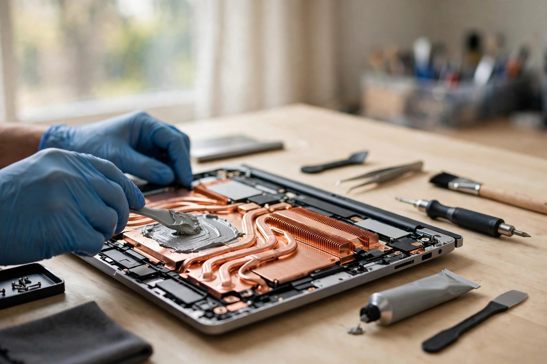
A laptop that keeps getting hotter, with fans spinning harder, does not always have a fan problem or a heat pipe problem. Often the real fault lies in a layer so thin it is almost invisible: the thermal interface material (TIM). This article covers only the TIM layer itself: thermal paste, liquid metal, phase-change materials, thermal pads, graphite sheets, application methods, bondline thickness, and contact pressure. Fan motors, fan control, temperature sensors, and the heatsink body itself are used only as comparisons; motherboard power delivery is out of scope. Do not open the machine yourself to work on the TIM layer; internal inspection should be left to qualified technicians. What readers can do is observe from outside, record temperatures, and describe symptoms accurately.
What the TIM layer does, and where it fails
Neither a chip surface nor a heatsink base is perfectly flat at microscopic scale. When the two faces are pressed together, only the high points truly touch, and the remaining gaps are filled with air, which conducts heat very poorly. The TIM fills those microscopic gaps, replacing air with a better-conducting material and lowering interface resistance. Intel's official guidance describes TIM as filling the natural microscopic surface defects and gaps between heatsink and chip; AMD's guidance likewise lists material conductivity, electrical conductivity, spreading behaviour, long-term stability and reliability, ease of use, and the pressure the heatsink applies through the TIM onto the package.
TIM failure is therefore not a vague statement that "the paste went bad". It happens at one or more of three places:
| Failure location | What happens | Field clue |
|---|---|---|
| Chip-to-TIM interface | TIM fails to wet the chip surface, or an oxide film, contamination, or old residue prevents bonding, leaving voids | Improvement after a re-paste fades quickly |
| Inside the TIM, the bondline | Carrier loss, filler separation, cracking, or voids raise resistance inside the layer | The temperature curve under the same load shifts upward as a whole |
| TIM-to-heatsink interface | TIM is pumped out, migrates, or fails first at the edges because pressure is uneven, leaving the central hot spot uncovered | Temperature swings unpredictably and the hot spot drifts |
Dry-out: the carrier leaves, the filler loses support
Thermal paste is generally a filler suspended in a carrier: the filler may be alumina, zinc oxide, boron nitride, or carbon-based particles, and the carrier is silicone oil or a synthetic oil. Dry-out is not the whole paste evaporating; it is the breakdown of the carrier-to-filler ratio. A reliability study in Electronics Cooling defines dry-out precisely: filler separates from the polymer matrix at high temperature, the matrix tends to flow out of the interface first, and the paste inside the interface dries out, raising field thermal resistance.
| Dry-out stage | Paste condition | Temperature behaviour |
|---|---|---|
| Early | Carrier begins to leave or migrate, paste viscosity rises, the filler skeleton barely holds contact | Slight rise only at the end of heavy loads |
| Middle | Filler loses carrier support, micro-voids appear inside the layer, resistance rises | The whole temperature curve under the same load shifts upward and throttling appears earlier |
| Late | Paste becomes powdery, hard lumps, or crumbs, and can no longer flow to refill gaps | Contact at the central hot spot deteriorates first, with irregular temperature jumps |
| Dry-out versus oil separation | Appearance | Mechanism | Consequence |
|---|---|---|---|
| Dry-out | The whole layer becomes dry and hard, powdery or lumpy | Carrier loss leaves the filler unsupported | Voids increase inside the layer, resistance rises |
| Oil separation | Oily shine at the edges, hard residue at the centre | Low-molecular-weight oil bleeds out of the thickener structure | One part of the same interface looks oily, another looks powdery, so resistance is uneven |
| Both together | Oil film and powdery lumps coexist | Separation and loss proceed together | Local high-resistance zones, gradual temperature drift rather than a jump |
Pump-out: every thermal cycle pushes a little more
Many users ask: What is the pump-out effect? Pump-out is the apparent seeping or migration of a low-viscosity material, such as thermal paste, out from between two faces over time. The cause is repeated mechanical stress from temperature change: the two faces expand and contract at different rates, stressing the material and causing separation. AMD's guidance uses the same language: low-quality compounds harden or leak out over time, causing overheating or early device failure, while higher-viscosity pastes on bare-die devices generally resist pump-out better.
Many users ask: What is the difference between pump-out and dry-out? Pump-out is a change of material position, while dry-out is a change of material composition, and the two often accelerate each other: pump-out thins the centre, so the remaining filler loses carrier more easily; dry-out removes the paste's ability to flow back and refill the gaps pump-out created. A diagnosis that mentions only one will miss half the mechanism.
| Four stages of pump-out | What happens | Result |
|---|---|---|
| Heating stage | Chip, heatsink base, and retainer expand at different coefficients, creating microscopic shear and a pressure gradient; paste softens and viscosity falls | Paste flows sideways more easily under pressure |
| Cooling stage | Materials contract out of step, paste is pulled and squeezed, and its viscoelastic nature tries to recover its shape | Layer thickness changes further |
| Repeated accumulation | Each heating and cooling cycle pushes a small amount of paste from the central high-pressure, high-temperature zone toward the low-pressure edges | The centre thins gradually, while paste piled at the edges contributes almost nothing to cooling |
| Critical point | The centre loses coverage, air or voids re-enter the interface | Local resistance jumps suddenly, and the temperature curve becomes unstable with a drifting hot spot |
| Conditions that accelerate pump-out | Mechanism | Why laptops are especially exposed |
|---|---|---|
| Low-viscosity formula | Low flow resistance, so shear pushes it out more easily | Thin machines have light heatsinks and short retainer travel |
| Large, frequent temperature cycles | Every cycle adds shear displacement | Long heavy loads alternating with shutdown or idle is the everyday laptop pattern |
| Excessive bondline thickness | A thicker layer has a larger absolute shear displacement | Retainer pressure is limited by the need to avoid cracking a bare die |
| Uneven contact pressure | The centre has the highest pressure and the largest temperature swings | Base or chip unevenness amplifies local differences |
| Uneven or bowed surfaces | Local pressure and layer thickness vary | Pump-out starts first at the weakest edge |
Cracking: the structural end-stage of dry-out
Cracking is the structural result of dry-out and phase separation reaching a late stage, not a separate chemical reaction. When carrier loss passes a threshold, the filler skeleton loses the binder's continuous support, and the layer can no longer follow the two faces as a continuous film under repeated expansion and contraction, so cracks and fragments appear.
| Crack source | How it forms | Diagnostic meaning |
|---|---|---|
| Shrinkage cracks | Carrier loss shrinks volume, internal tensile stress exceeds bond strength | Net-like or radial cracks; each crack is itself an air channel |
| Shear cracks | Different expansion coefficients shear an already hardened layer repeatedly | Cracks extend along the shear direction; temperatures swing with temperature and retainer micro-movement |
| Edge peel cracks | Pump-out thins or piles the edges unevenly, concentrating stress at the thickness step | Cracks run from the edge toward the centre; the hot spot shifts with temperature |
Phase separation and oil bleed: oil and powder part ways
Phase separation means filler and carrier go their separate ways: oily carrier gathers as a bright film or bleeds outward, while filler gathers as powder or dry lumps. ARCTIC lists non-bleeding alongside non-drying as a long-term performance claim.
| Phase separation triggers | Mechanism | Note |
|---|---|---|
| Prolonged high temperature | Accelerates carrier evaporation and migration, weakening filler coating | Effect depends on the formula |
| High humidity | Research shows high humidity can change paste-layer resistance | Direction and size depend on filler and resin system; no blanket rule applies |
| Mismatched formula | Filler particle size, surface treatment, and carrier viscosity out of balance | Separation is easier under long cycling |
| Pressure and shear | Pump-out preferentially transports binder outward | The centre's filler fraction rises abnormally, accelerating separation |
Oxidation and surface degradation: a new paste can fail in the same place
Oxidation in TIM failure has two levels that must be kept apart.
| Oxidation level | Where it happens | Effect |
|---|---|---|
| Inside the TIM and its filler | Some metal fillers and carriers change chemically under prolonged heat and moisture | Paste structure changes, volume changes, or resistance rises, not always visible |
| On the contact surfaces | Oxide films form on copper, aluminium, and nickel-plated copper bases | Surface energy changes, wetting falls, paste cannot fully bond, and voids remain in the interface |
Seven TIM material classes compared: numbers cannot be ranked across brands
All values below are manufacturer nominal values, not measurements made for this article; different manufacturers test differently, so direct cross-brand ranking is not valid. Measurements also show that a conventional paste's effective conductivity in a real thin layer, at real pressure and temperature, is often lower than the nominal bulk value on the package, because contact resistance takes a large share.
| Class | Form and filler | Manufacturer nominal conductivity | Electrical conductivity | Durability tendency | Suitable use | Risks and limits |
|---|---|---|---|---|---|---|
| Conventional silicone paste | Silicone oil carrier with alumina or zinc oxide fillers | Generally low to mid-range, commonly about 1 to 6 W/m·K | Generally insulating, per individual datasheet | Moderate; oil separation and pump-out under long thermal cycling | Everyday and office laptops, a safe general choice | An over-thick layer raises resistance instead |
| Carbon-based paste | Silicone gel or oil carrier with carbon particles | Nominal values vary widely by manufacturer; check the individual datasheet | For ARCTIC MX-6, officially non-conductive | Relatively good; high viscosity and low-bleed design target long-term stability | Gaming and office machines seeking a balance of performance and low short-circuit risk | High-viscosity paste is hard to spread evenly with a blade |
| Metal-oxide performance paste | Silicone oil carrier with fine nano alumina or zinc oxide fillers | Thermal Grizzly Kryonaut older datasheet 12.5 W/m·K; Kryonaut Extreme older datasheet 14.2 W/m·K | Manufacturer states non-conductive | Better early performance, but some reviews note performance can fall back after thermal cycling | High-power gaming machines, machines sensitive to early temperatures | High performance does not equal high durability; judge the two separately |
| Liquid metal | Gallium-indium-tin alloy, liquid at room temperature | Thermal Grizzly's current official page no longer publishes a general W/m·K value since late 2020, so this article does not use an old number as a current nominal value | Conductive; the manufacturer warns in bold about conductivity and never contacting aluminium | The metal itself does not dry out, but alloying, migration, and pump-out remain | Only confirmed copper or nickel-plated copper bases with full barriers and insulation protection | Absolute limits are listed in the next section |
| Phase-change material | Polymer phase-change system with conductive filler, a solid sheet at room temperature | Honeywell PTM7950 manufacturer or distributor data: 8.5 W/m·K | Generally non-conductive, per individual datasheet | More resistant to pump-out and dry-out | Gaming machines, ultra-thin machines, machines where fewer re-pastes are wanted | In low-power use that never reaches phase-change temperature, forming is incomplete |
| Silicone thermal pad | Silicone base with ceramic or boron nitride fillers, pre-formed sheet | By grade, commonly about 1 to 12 W/m·K in manufacturer nominal values | Generally insulating, per individual datasheet | More stable, no dry-out, no pump-out, but can take a permanent compression set | Memory, power stages, and chipsets with larger, uneven gaps | The absolute limit is using the wrong thickness in place of the original pad |
| Graphite sheet | Pyrolytic or flexible graphite sheet, layered carbon structure | In-plane values can reach hundreds to over a thousand W/m·K, but through-plane values are far lower, often below 20 W/m·K | Conductive | No dry-out, no pump-out, better long-term stability | Office machines or specific ultra-thin designs wanting fewer re-pastes | Damaged, frayed sheets must not be reused; alignment matters |
| Three common misreadings of conductivity | Misreading | Correct understanding |
|---|---|---|
| A bigger number always means lower temperature | Choosing by nominal conductivity alone | Total interface resistance combines the paste's own resistance with two contact resistances; in thin layers, contact resistance often dominates |
| All manufacturers' numbers share one ruler | Ranking brands by one number | Test method, pressure, thickness, temperature, and surface roughness all change results; Noctua publicly explains why it does not publish a single conductivity figure, and ARCTIC’s datasheets likewise give no single figure |
| Laboratory effective conductivity equals the package number | Treating a bulk-material number as installed-interface performance | Bulk material and installed interface are two different measurements; real thin-layer effective values are often lower |
Liquid metal: chemical risk behind the performance
Many users ask: Is liquid metal suitable for every laptop? The answer is no. Liquid metal suits only confirmed copper or nickel-plated copper bases with full barriers and insulation protection in an original or professionally designed application. Commuting vibration and repeated thermal cycling increase migration risk, so mobile laptop use carries higher risk than a machine that stays on a desk.
Many users ask: Why must liquid metal never touch aluminium? Because gallium reacts very strongly with aluminium: Indium Corporation notes gallium can corrode through thin aluminium foil within hours at room temperature, faster at high temperature, and Thermal Grizzly likewise forbids aluminium contact. On copper, CuGa2 forms; on nickel-plated copper, NiGa5 forms a thinner reaction layer, and the manufacturer recommends nickel-plated copper as the more stable long-term contact face.
| Liquid metal risk | Mechanism | Consequence |
|---|---|---|
| Aluminium corrosion | Gallium reacts strongly with aluminium | Thin aluminium foil can be corroded through within hours at room temperature, faster when hot |
| Alloying | CuGa2 on copper, NiGa5 on nickel-plated copper | Contact-face properties change, so long-term behaviour differs from early behaviour |
| Migration | Liquid at room temperature, high flow and migration risk | A single spilled drop can cause a short circuit |
| Conductive short circuit | Liquid metal conducts electricity | Use near exposed circuitry without protection can short the board |
| Liquid metal suitability and limits | Situation | Judgement |
|---|---|---|
| Confirmed copper or nickel-plated copper base, full barrier and insulation protection | A professionally designed application | Decided by the design, never assumed |
| Aluminium base, or base material unknown | Absolute limit | Must not be considered |
| Inadequate protection around the die, exposed circuitry nearby | Absolute limit | Spill risk is unacceptable |
| Frequent commuting vibration and mobile use | Risk increased | Migration risk is higher than for a desk-bound machine |
Need a laptop repair expert?
Free diagnosis · Transparent pricing · No fix, no fee · 180-day warranty
Phase-change pads: a solid-soft-solid cycle aimed at pump-out
Many users ask: What is the difference between a phase-change pad and conventional thermal paste? A phase-change material is a solid sheet at room temperature that softens or melts when heated, refills micro-gaps, and resolidifies on cooling, so its position is relatively fixed at the end of each cycle and it resists pump-out and dry-out better. Conventional paste stays paste-like across the whole working temperature range, so its position moves more easily under cycling.
Many users ask: Does a phase-change pad need a burn-in? A phase-change pad needs to reach its phase-change temperature to complete forming. For Honeywell PTM7950, sources record a phase-change range of about 45 to about 52 degrees, with a recommendation to hold at least 60 degrees for a period to reach minimum bondline; minimum bondline is about 17 to 20 micrometres. In low-power use that never reaches phase-change temperature, forming stays incomplete and early resistance stays high.
| Phase-change pad points | Content | Caution |
|---|---|---|
| Form | Solid sheet at room temperature, commonly 0.25 mm, with a 0.2 mm version also listed | Check genuine specifications; do not substitute a non-original thickness |
| Phase-change temperature | About 45 to about 52 degrees; full change needs the whole sheet near 50 degrees | Low-power use may never reach it |
| Recommended clamping pressure | About 30 to 40 psi | Insufficient pressure affects forming and bondline |
| Minimum bondline | About 17 to 20 micrometres, typically below 50 micrometres | Wrong thickness changes the bondline |
| Reliability test conditions | Manufacturer reliability data mentions 1,000 hours at 150 degrees and 1,000 thermal cycles with low resistance maintained | These are manufacturer test conditions, not an everyday lifespan guarantee |
Thermal pads: the wrong thickness lifts the heatsink
Many users ask: What happens if a thermal pad of the wrong thickness is used? Thermal pads suit memory, power stages, and chipsets with larger, uneven gaps; they are not a direct replacement for the thin paste layer on a processor or graphics chip. Too thick, and the pad lifts the heatsink so the processor interface loses contact; too thin, and gaps stay partly empty, leaving sections suspended.
| Thermal pad parameters | Content | Selection note |
|---|---|---|
| Hardness | Measured in Shore OO, commonly about 15 to 80 Shore OO | Too hard a pad bonds poorly at low pressure; too soft a pad is over-compressed or squeezed out at high pressure |
| Thickness | Commonly 0.5 to 5.0 mm, with compression allowance needed | Must match the original thickness; hardness and compression must be judged together with gap and pressure |
| Durability | More stable, no dry-out, no pump-out | Can take a permanent compression set, harden at the edges, and lose surface bonding |
| Electrical conductivity | Generally insulating | Check the individual datasheet |
Graphite sheets: the in-plane number is not the through-plane number
Many users ask: Why cannot a graphite sheet's conductivity be judged by its in-plane value alone? Because graphite's layered carbon structure makes in-plane and through-plane conduction very different: in-plane values can reach hundreds to over a thousand W/m·K, but through-plane values are far lower, often below 20 W/m·K. A processor interface needs through-plane transfer, not in-plane spreading, so using an in-plane number to predict interface performance is a misreading.
Many users ask: What risk does graphite's conductivity create? Technical data states clearly that graphite conducts electricity, so contact with exposed conductors, battery tabs, or antenna traces can cause short circuits or change grounding and radio-frequency behaviour. Graphite sheets are flexible but brittle; edges wear, delaminate, and shed debris; no-flow, no-dry-out, and reusability apply only while the sheet is undamaged.
| Graphite misreadings and facts | Misreading | Fact |
|---|---|---|
| The in-plane number equals interface performance | Expecting a large temperature drop from a hundreds-scale number | The interface needs through-plane transfer, whose value is far lower |
| Graphite sheets can be cut and placed freely | Continuing to use a damaged edge | A sheet with damaged edges or debris must not be reused; misalignment creates hot spots |
| Graphite sheets insulate | Allowing contact with exposed circuitry | Graphite conducts; without insulation separation, contact with exposed conductors can short |
Application methods and bondline: coverage matters more than the pattern name
Many users ask: What is the difference between dot, cross, and spread application? The table below describes how paste spreads under pressure in principle, not an instruction manual. Every method must answer the same question: under retainer pressure, can the paste form a complete, continuous, thin film with no large trapped bubbles?
| Method | Principle | Coverage tendency | Bubble risk | Main drawback |
|---|---|---|---|---|
| Centre dot | One central dot, spread outward radially by retainer pressure | Thickest at the centre, thinning outward; good for small dies, corners may fall short on large dies | Lower, as paste pushes air outward from a single point | Central thickness raises local resistance; large-die corner starvation risk |
| Cross and X shape | Two diagonals crossing at the centre, starting points already closer to the corners | Better large-die coverage, higher corner reach than a dot | Lower, lines still push outward | Line ends near the edge can overflow; the crossing point runs thick |
| Lines | One or more parallel lines spreading sideways | More even thickness distribution, suits rectangular dies | Low to moderate; lines must be continuous and even, broken lines trap air | Line-end overflow risk; uneven spacing gives uneven thickness |
| Multiple dots | A centre dot plus surrounding dots, pre-distributing paste | More complete coverage, higher corner reach | Moderate to high; air can be trapped where dots meet | Harder dose control; excess overflows; bubble risk at dot junctions is higher than a single dot |
| Blade spread and pre-applied film | A blade or pre-applied film forms an even thin layer over the whole contact face first | Theoretically most even, thickness pre-controlled | Depends on technique; repeated strokes, an uneven blade, or dry paste can trap air; some high-viscosity products must not be blade-spread | Spreading most easily introduces bubbles and uneven thickness; pre-applied films are limited by film thickness and alignment accuracy |
Many users ask: Does applying more thermal paste give better cooling? The answer is no. The thicker the bondline, the higher the resistance, and bondline thickness is set jointly by face flatness, TIM thickness, and retainer clamping force. Too much paste thickens resistance; too little paste, uneven coverage, bubbles, uneven pressure, old residue, or an untreated oxide film can all make a re-paste worse than before.
Many users ask: What is bondline thickness? Bondline thickness is the final thickness of the TIM layer clamped between chip and heatsink. Thermal resistance is set jointly by face flatness, TIM thickness, and retainer clamping force, so bondline is not the paste's own labelled thickness but the actual installed layer thickness. A phase-change pad's minimum bondline is about 17 to 20 micrometres, typically below 50 micrometres; a conventional paste's bondline varies with dose, viscosity, and pressure, and there is no single number for all models.
| Bondline and resistance | Situation | Effect |
|---|---|---|
| Bondline too thick | The paste's own resistance rises with thickness | Overall interface resistance rises, temperatures shift upward |
| Bondline too thin to keep a skeleton | Filler sits almost two-dimensionally, losing three-dimensional skeleton support | Under load and thermal cycling the structure destabilises quickly and cracks more easily |
| Uneven bondline | Some areas thick, some thin, pressure uneven | Thin areas fail first, thick areas run high resistance, hot spots drift |
| Old residue raising the bondline | Old paste or oxide film left untreated | The new layer bonds poorly in the same place |
| Pressure problems | Mechanism | Field behaviour |
|---|---|---|
| Insufficient pressure | The layer slides under cycling, bonding is inadequate | Acceptable bonding at first, gradual temperature drift as cycles accumulate |
| Uneven pressure | Local thickness varies, thin areas fail first | Temperatures swing unpredictably, hot-spot position is unstable |
| Over-thick pad lifting the heatsink | The processor interface loses contact | Temperatures stay high even with brand-new paste |
| Uneven surfaces | Local pressure and thickness vary | Pump-out starts first at the weakest edge |
Layered exclusion: prove the problem is really in the TIM layer
What the TIM layer cannot do matters as much as what it can: it cannot fix a warped cold plate, a loose retainer, or an over-thick thermal pad lifting the heatsink; it cannot replace airflow and exhaust, nor unblock dust-clogged fins; it cannot correct wrong power settings or fan curves; and it cannot raise the heatsink module's own cooling ceiling. So when temperatures rise, the first question should not be which paste is best, but whether the resistance increase is really in the TIM layer.
| Seven layered-exclusion steps | What to do | Judgement focus |
|---|---|---|
| Step 1, fixed-condition recording | Fix room temperature, power mode, and load program; record idle and heavy-load temperatures | Without fixed conditions, temperature numbers cannot be compared |
| Step 2, curve shape | Check whether temperature rises smoothly, jumps suddenly, or jumps irregularly | Smooth rise points to overall resistance increase, a sudden jump to dry-out or a contact break, irregular jumps to cracking or unstable contact |
| Step 3, fan comparison | Note fan speed, noise, and exhaust temperature changes | When the fan is at fault, exhaust and speed change first; see the diagnostic service for inspection steps and pricing for fee structure |
| Step 4, heat pipe and fin comparison | Note fin temperature distribution and exhaust temperature | Fins cool while the chip is very hot points to heat not being moved; fins very hot with weak exhaust points to heat not being removed |
| Step 5, sensor cross-check | Compare readings from different sensor points for contradictions | When one sensor disagrees while others look normal, suspect the sensing or reading chain first |
| Step 6, time pattern | Record whether the problem appears at boot, after a period of use, or intermittently | At boot points to contact or installation, gradual onset to ageing, intermittent behaviour to unstable contact or cracking |
| Step 7, combined judgement before acting | Put all six steps together before deciding on TIM-layer work | One symptom alone cannot settle it, and a re-paste cannot fix fan, heat pipe, or sensor faults |
Many users ask: How can you tell whether a temperature problem comes from the TIM layer or the heat pipe? A heat pipe fault typically shows heat not being moved: the chip is very hot while the fins stay relatively cool, or the pipe tail is unusually cold; TIM failure is a rise in interface resistance, where heat enters the heatsink less efficiently but the pipe's own transport ability may be intact. Curve shapes differ too: heat pipe dry-out often jumps suddenly, while TIM ageing usually drifts gradually.
| Comparison: TIM versus other parts | TIM layer failure | Fan path | Heat pipe path | Sensor path |
|---|---|---|---|---|
| Typical temperature curve | Gradual upward shift, earlier throttling | Speed or exhaust changes first, temperatures follow | Sudden jump, or unusually cold pipe tail | One reading abnormal, others not in step |
| Key clue | Load-to-idle temperature gap widens, curve unstable | Noise, speed, and exhaust temperature change together | Heat not moved, abnormal fin temperature distribution | Readings contradict each other |
| Does a re-paste help | Only if the fault is really in the TIM layer | No | No | No |
Hong Kong context: humidity, commuting, and thermal cycling combined
Many users ask: How does Hong Kong's humid weather affect the TIM layer? The Hong Kong Observatory's 1991 to 2020 average relative humidity is 78%, and high humidity has been shown to change paste-layer resistance, with the exact effect depending on the filler and resin system's response to moisture. It cannot be said flatly that humidity always worsens paste, nor that it never matters. Humidity also accelerates oxidation and contamination of contact surfaces, worsening wetting and bonding of new paste.
Many users ask: Do commuting vibration and temperature cycling accelerate TIM failure? Yes, and the three factors combine. Daily commuting vibration adds mechanical disturbance to the interface, raising migration risk for flowable materials such as liquid metal and alignment risk for graphite sheets; moving between air-conditioned rooms and outdoors adds repeated expansion and contraction, amplifying pump-out shear; high humidity affects the chemical stability of paste and contact surfaces. When all three are present, material choice should favour pump-out-resistant and separation-resistant structures, such as high-viscosity paste or phase-change material, rather than chasing the highest nominal number.
| Hong Kong factors | Mechanism | Selection and judgement implication |
|---|---|---|
| High humidity, average relative humidity 78% | Can change paste-layer resistance, accelerates surface oxidation and contamination | Effect varies by formula; judge by temperature curves, not by weather alone |
| Commuting vibration | Extra mechanical disturbance at the interface | Higher migration risk for flowable materials, higher alignment drift for graphite sheets |
| Air-conditioned room to outdoor cycling | Repeated expansion and contraction, amplifying shear displacement | Higher pump-out and cracking risk; temperature records must fix room temperature and load conditions |
| Long heavy loads alternating with idle | Many cycles, large amplitude | Gradual drift reflects TIM ageing better than a single hot reading |
Common misdiagnoses: six reasons a re-paste can make things worse
Many users ask: Why might temperatures be higher after reapplying thermal paste? Six TIM-layer reasons below often occur together.
| Reason a re-paste gets worse | Mechanism | How to avoid misjudgement |
|---|---|---|
| Too much paste | Bondline thickens, resistance rises | Dose logic is just enough to fill micro-gaps, not more is safer |
| Too little paste or uneven coverage | Corner starvation, central hot spot uncovered | Coverage matters more than the pattern name |
| Bubbles trapped in the layer | Air conducts extremely poorly, local resistance jumps | A bubble is resistance, not a minor flaw |
| Uneven pressure | Local thickness varies, thin areas fail first | Tightening harder alone does not fix unevenness |
| Old paste not fully removed | Residue raises the bondline | The new layer bonds poorly in the same place |
| Oxide film on the contact face untreated | Surface energy changes, new material cannot wet | Brief improvement, then a return to the old behaviour |
Repair, replace, or upgrade decision framework
| Situation | Decision direction | Reason |
|---|---|---|
| Temperature curve drifting upward gradually, layered exclusion points to the TIM layer, paste dried out or pumped out | Replace with the same type of paste, or switch to a phase-change material | Treats the confirmed failure mechanism |
| Paste repeatedly pumps out, model cycles thermally often, retainer pressure is adequate | Consider a phase-change material | Resolidifying on cooling keeps its position relatively fixed, resisting pump-out better |
| Fewer re-pastes wanted, office machine or specific ultra-thin design | Consider a graphite sheet, but only as the design decides | No dry-out, no pump-out, but conductive and demanding on flatness |
| Larger, uneven gaps on memory or power-stage components | Use a thermal pad of the correct thickness | Paste cannot fill large gaps; wrong thickness lifts the heatsink or leaves sections suspended |
| Aluminium base, unknown base material, or inadequate surrounding protection | Never consider liquid metal | Aluminium corrosion and conductive short-circuit risks are unacceptable |
| Layered exclusion points to fan, heat pipe, or sensor | Fix that part first, do not change TIM | Changing TIM cannot fix other parts' faults |
| Old model with retainer or base already deformed | Judge by inspection results, do not assume an upgrade helps | Deformation makes pressure and thickness uneven, so a material change alone may not improve things |
What to record before sending a machine for inspection
Readers should not handle the internal TIM layer themselves, but they can record useful information for layered judgement: idle and heavy-load temperature readings, changes in fan noise and exhaust feel, whether the problem appears at boot or after a period of use, whether temperature rises smoothly or jumps suddenly, and any major recent change in usage environment, such as moving from long air-conditioned use to outdoor use. Records should fix power mode and load program, or numbers from different conditions cannot be compared. For inspection arrangements, see the diagnostic service; for fee structure, see pricing.
Viscosity, filler, and durability: a three-way trade-off
Viscosity, filler, and durability pull against each other and cannot be optimised one at a time. High viscosity resists pump-out and leakage better, but spreads with difficulty and demands more from retainer pressure and surface flatness; under a low-pressure structure it may leave coverage gaps. Low viscosity spreads easily and bonds well at first, but is more easily displaced and separated under thermal cycling. Larger filler particles set a higher floor for minimum bondline; finer particles allow thinner layers, but filling ratio and viscosity must stay balanced, since over-filling makes paste dry and brittle. Carrier stability matters equally: low-bleed formulas and thixotropic designs exist to keep filler and carrier uniform under prolonged heat and pressure, rather than separating. A genuinely high-performance paste must therefore answer three questions at once: what is its early resistance, what is its resistance after a thousand cycles, and can it form a complete thin film under this model's retainer pressure? Any comparison that answers only the first question is incomplete.
Selection decision tree: by model and usage pattern
For office machines, stability and low risk come first: conventional silicone paste or carbon-based paste is enough, and the priorities are complete coverage and even pressure, not chasing the highest nominal number. For gaming machines, cycling durability comes first: if paste repeatedly pumps out, consider a phase-change material; if power is high but the environment is fixed and retainer pressure is adequate, a performance paste is acceptable, provided its durability is not assumed equal to a conventional paste's. For ultra-thin machines, bondline and the pressure ceiling come first: bare-die direct contact and short retainer travel mean selection must follow the model's original thickness and pressure conditions, and any substitution with the wrong pad or phase-change thickness changes the bondline. For older machines, retainer and base condition come first: if the base is deformed or retainer spring force has faded, a material change alone may not help, and inspection results must decide. Every model shares one hard line: aluminium or unknown base material, or inadequate surrounding protection, means liquid metal is never considered; and any design where a graphite sheet would touch exposed conductors is likewise never considered.
Conclusion
TIM-layer failure is rarely a single cause: dry-out changes composition, pump-out changes position, cracking opens air channels, phase separation splits oil from powder, oxidation stops new material from wetting, and pressure and thickness set the whole layer's resistance starting point. Liquid metal, phase-change pads, thermal pads, and graphite sheets each have suitable uses and absolute limits, and no single material suits every model. The safest judgement order is always the same: record temperature curves under fixed conditions first, exclude fan, heat pipe, and sensor layers next, and only then decide on TIM-layer work. If inspection arrangements or fees are unclear, see the diagnostic service and pricing, and rely on a written quotation after inspection.
Shop information: Room 1209, Daly Plaza, Shek Mun, Shatin; telephone +852 2186 8010; WhatsApp +852 6558 6806; business hours 12:00–19:00.
If the symptoms above are already present, record the temperature curve first, then check the diagnostic service and pricing.
Disclaimer: This article is for reference only; actual conditions must be judged by professional inspection results. Different models have different structures and original specifications, and handling should follow the written quotation and professional advice after inspection.
Need Professional Laptop Repair?
Laptop King has 15+ years of repair experience in Shek Mun, Sha Tin. Free diagnosis, transparent pricing, no fix no fee. 180-day warranty for your peace of mind.